Teknomotor ATC41-ISO20 User manual
ATC41-ISO20 INSTRUCTION MANUAL
DOC.U.A.001.DOCX Rev.02 del 11/11/2019 2
ATC41-ISO20
INSTRUCTION
MANUAL
Practical guide to the correct use of
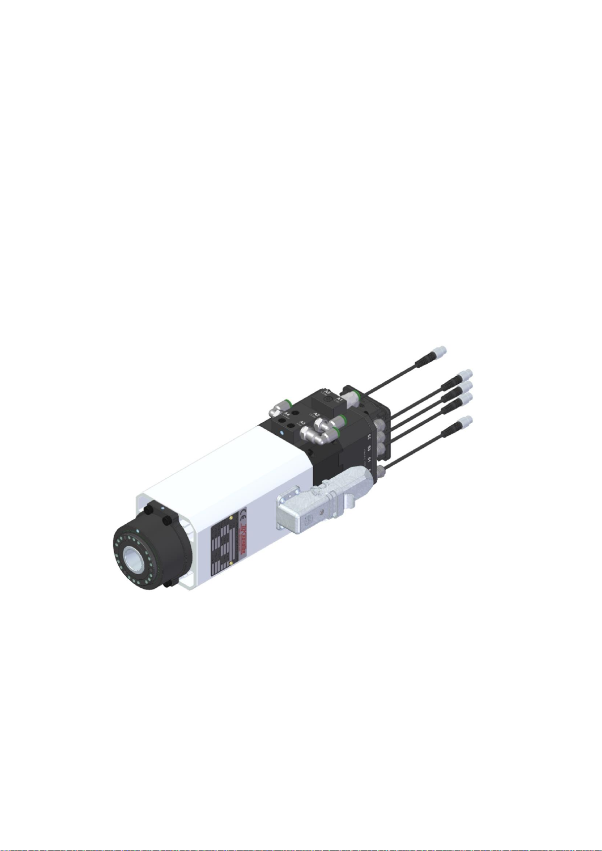
Automatic Tool Changer ISO20

ATC41-ISO20 INSTRUCTION MANUAL
DOC.U.A.001.DOCX Rev.02 del 11/11/2019 3

ATC41-ISO20 INSTRUCTION MANUAL
DOC.U.A.001.DOCX Rev.02 del 11/11/2019 4
This manual contains information protected by copyright. It and its attachments shall not be
photocopied or reproduced in any form, either fully or in part, without the prior written consent of
TEKNOMOTOR S.R.L.

ATC41-ISO20 INSTRUCTION MANUAL
DOC.U.A.001.DOCX Rev.02 del 11/11/2019 5
ATC41-ISO20 INSTRUCTION MANUAL
DOC.U.A.001.DOCX Rev.02 del 11/11/2019 6
USER MANUAL REVISION TABLE:
Revision no.
Revision date
Revision description
Author
02
11/11/2019
Aggiunto render al § 8.3.1
D. Bottarel
01
21/06/2019
Aggiunto tavole
D. Bottarel
00
13/12/2018
Emissione
D. Bottarel
Technical Department of TEKNOMOTOR S.R.L. has written this user manual.
The manual addresses to installers, operators and service technicians working with TEKNOMOTOR S.R.L.
electrospindles.
TEKNOMOTOR S.R.L. supplies the manual together with its electrospindles at the last revision available.
ATTACHMENTS:
Attachments listed below are integral part of the user manual and shall be read and understood in conjunction
with to avoid missing important information:
•GENERAL VIEW DRAWINGS WITH OVERALL DIMENSIONS, PERFORMANCE DATA AND
ELECTRICAL SPECIFICATIONS
•MANUFACTURER DECLARATION OF CONFORMITY (EU)
•POWER-TORQUE SPEED DIAGRAM (IF REQUESTED BY CUSTOMER)
Listed attachments can be embedded in this user manual or constitute a separate document or data sheet.
Check that all above documents are disposable before installing, operating or maintaining TEKNOMOTOR
S.R.L. electrospindles covered by this user manual.
Ask Technical Department of TEKNOMOTOR S.R.L. tecnico@teknomotor.com for missing information or
documentation.

ATC41-ISO20 INSTRUCTION MANUAL
DOC.U.A.001.DOCX Rev.02 del 11/11/2019 7
ATC41-ISO20 INSTRUCTION MANUAL
DOC.U.A.001.DOCX Rev.02 del 11/11/2019 8
DISCLAIMER:
USE THE ELECTROSPINDLE ONLY FOR THE PURPOSE FOR WHICH
TEKNOMOTOR S.R.L. DESIGNED IT.
SAFE OPERATION DEPENDS ON THIS.
WARRANTY AND LIABILITY UNDER GENERAL SALES CONDITIONS OF
TEKNOMOTOR DEPEND ON THIS AND THEY WILL LAPSE IF THE
INSTRUCTIONS PROVIDED IN THIS USER MANUAL WILL NOT STRICTLY
APPLIED.
INSTALL THE ELECTROSPINDLES AS DESCRIBED IN THE FOLLOWING
SECTIONS OF THIS MANUAL AND ATTACHED TECHNICAL
DOCUMENTATION.
SAFE OPERATION DEPENDS ON THIS.
WARRANTY AND LIABILITY UNDER GENERAL SALES CONDITIONS OF
TEKNOMOTOR DEPEND ON THIS AND THEY WILL LAPSE IF THE
INSTRUCTIONS PROVIDED IN THIS USER MANUAL WILL NOT STRICTLY
APPLIED.

ATC41-ISO20 INSTRUCTION MANUAL
DOC.U.A.001.DOCX Rev.02 del 11/11/2019 9

ATC41-ISO20 INSTRUCTION MANUAL
DOC.U.A.001.DOCX Rev.02 del 11/11/2019 10
INDEX
USER MANUAL REVISION TABLE:...............................................................................................6
ATTACHMENTS:............................................................................................................................6
DISCLAIMER:.................................................................................................................................8
INDEX...........................................................................................................................................10
1. INTRODUCTION......................................................................................................................14
1.1. SYMBOLS AND SAFETY SIGNS USED IN THE MANUAL ........................................................... 14
1.2. PURPOSE ....................................................................................................................................... 15
2. WARNING AND SAEFTY PRECAUTIONS..............................................................................16
2.1. RISKS ASSOCIATED WITH IMPROPER USE AND HANDLING .................................................. 16
2.2. RISKS SPECIFIC TO ELECTROSPINDLE MAINTENANCE ......................................................... 17
3. GENERAL INFORMATION ......................................................................................................17
3.1. PROPER USE OF ELECTROSPINDLE.......................................................................................... 17
3.2. RANGE OF APPLICATION............................................................................................................. 18
4. TECHNICAL SPECIFICATIONS ..............................................................................................19
4.1. THE MAIN PARTS OF THE ELECTROSPINDLE........................................................................... 19
4.2. IDENTIFYNG THE MOTOR DATA FROM THE NAME PLATE...................................................... 20
4.3. GENERAL VIEWS, OVERALL DIMENSIONS AND PERFORMANCE .......................................... 20
5. TRASPORT, PACKAGING, UNPACKAGING AND STORAGE................................................21
5.1. PACKAGING AND LIFTING............................................................................................................ 21
5.2. STORAGE ....................................................................................................................................... 21
6. INSTALLATION........................................................................................................................22
6.1. CHECKING FOR DAMAGE............................................................................................................. 22
6.2. PROVISION OF ON SITE INSTALLATION EQUIPMENT.............................................................. 22
6.3. MECHANICAL CONNECTIONS ..................................................................................................... 22
6.3.1. POSITIONING OF ELECTROSPINDLE...................................................................................... 22
6.3.2. ELECTROSPINDLE RESTING SURFACE................................................................................. 22
6.3.3. TOOL CHANGE SYSTEM........................................................................................................... 23
6.3.4. FIXING ELECTROSPINDLE ....................................................................................................... 23
6.4. PNEUMATIC CONNECTION .......................................................................................................... 23
6.4.1. AIR PURITY................................................................................................................................. 23
6.4.2. PNEUMATIC CONNECTION DIAGRAM .................................................................................... 24
6.5. PNEUMATIC SPINDLE NOSE CLEANING .................................................................................... 26
6.6. NOSE PRESSURISATION.............................................................................................................. 26
6.7. ELECTRICAL CONNECTIONS....................................................................................................... 26
6.7.1. STANDARD LAYOUT OF POWER CONNECTOR..................................................................... 26

ATC41-ISO20 INSTRUCTION MANUAL
DOC.U.A.001.DOCX Rev.02 del 11/11/2019 11
6.7.2. LAYOUT OF SIGNAL CONNECTOR.......................................................................................... 27
6.8. ELECTRIC FAN............................................................................................................................... 27
7. GENERAL CHECKS AFTER INSTALLATION IN THE MACHINE AND PRIOR START-UP.....28
7.1. CHECKING ON THE ELECTROSPINDLE PRIOR TO START-UP................................................ 28
7.2. CHECKING ON THE ELECROSPINDLE AT THE TIME OF FIRST START-UP............................ 29
7.3. CHECKING ON THE ELECTROSPINDLE BEFORE RUNNING IT................................................ 29
8. OPERATION OF THE ELECTROSPINDLE .............................................................................30
8.1. CLIMATIC LIMITATIONS ................................................................................................................ 30
8.2. FORECAST AND NON FORECAST USE ...................................................................................... 30
8.3. RUNNING IN.................................................................................................................................... 30
8.4. WARMING UP................................................................................................................................. 31
8.5. TOOL-HOLDER LOCKING AND EXPULSION DEVICE................................................................. 31
8.6. TOOL-HOLDER CONE ................................................................................................................... 31
8.7. INSTALLATION OF THE PULL STUD ON THE ISO20 CONE....................................................... 31
8.8. GENERAL RACCOMANDATION FOR THE TOOL HOLDER CONES.......................................... 32
8.9. TOOL MOUNTING –TOOLHOLDER ............................................................................................. 32
8.10. TOOL MOUNTING –TOOLHOLDER WITH CONICAL SEAT FOR ER DIN 6499.................... 34
Excessive tool run-out causes premature wear of bearings. ..................................................................... 34
8.11. MAXIMUM RUN-OUT AND VIBRATION VALUES ..................................................................... 35
8.12. SPEED LIMITS............................................................................................................................ 35
8.13. WHAT TO DO IF THE TOOL IS BLOKED ON THE PIECE BEING WORKED .......................... 36
8.14. SENSORS ................................................................................................................................... 36
8.14.1. TECHNICAL CHARACTERISTICS OF THE INDUCTIVE SENSORS.................................... 36
8.14.2. STATUS MODES OF THE ELECTROSPINDLE AND CORRESPONDING OUTPUTS ........ 37
8.14.3. TRIMMING SENSORS............................................................................................................ 38
8.14.4. SENSOR S3 OUTPUT (option)............................................................................................... 39
8.14.5. THERMAL ALARM .................................................................................................................. 39
9MAINTENANCE.......................................................................................................................40
9.1. SCHEDULED MAINTENANCE AND CLEANING THE SPINDLE SHAFT TOOL HOUSING......... 41
9.1.1. CHECK THE CLEANING OF TOOL-HOLDER CONE AND CONICAL HOUSING OF THE
ELECTROSPINDLE SHAFT ...................................................................................................................... 41
9.1.2. PROTECTING THE CONICAL SEAT IN THE SPINDLE SHAFT ............................................... 42
9.1.3. CLEANING THE TOOL-HOLDER CONE.................................................................................... 42
9.1.4. CHECK THE CONNECTIONS .................................................................................................... 42
9.2. OCCASIONAL MAINTENANCE...................................................................................................... 42
10. TROUBLESHOOTING .......................................................................................................43
11. DISPOSING OF THE ELECTROSPINDLE.........................................................................43
12. USEFULL ADRESSES.......................................................................................................43
APPENDIX: ATC41 DRAWINGS AND POWER-TORQUE CURVES............................................45

ATC41-ISO20 INSTRUCTION MANUAL
DOC.U.A.001.DOCX Rev.02 del 11/11/2019 12
Figure 1 Main part of the electrospindle .......................................................................................................... 19
Figure 2 Typical Teknomotor electrospindle nameplate.................................................................................. 20
Figure 3 Air connections.................................................................................................................................. 25
Figure 4 Power supply connector.................................................................................................................... 26
Figure 5 Electrical sensor connection.............................................................................................................. 27
Figure 6 Pin number........................................................................................................................................ 27
Figure 7 Sensor plug ....................................................................................................................................... 27
Figure 8 V-f pattern.......................................................................................................................................... 28
Figure 9 Sensors cover dismounting Figure 10 Trimming sensor system............................................. 38
This manual contains information protected by copyright. It and its attachments shall not be
photocopied or reproduced in any form, either fully or in part, without the prior written consent of
TEKNOMOTOR S.R.L.

ATC41-ISO20 INSTRUCTION MANUAL
DOC.U.A.001.DOCX Rev.02 del 11/11/2019 13
ATC41-ISO20 INSTRUCTION MANUAL
DOC.U.A.001.DOCX Rev.02 del 11/11/2019 14
1.INTRODUCTION
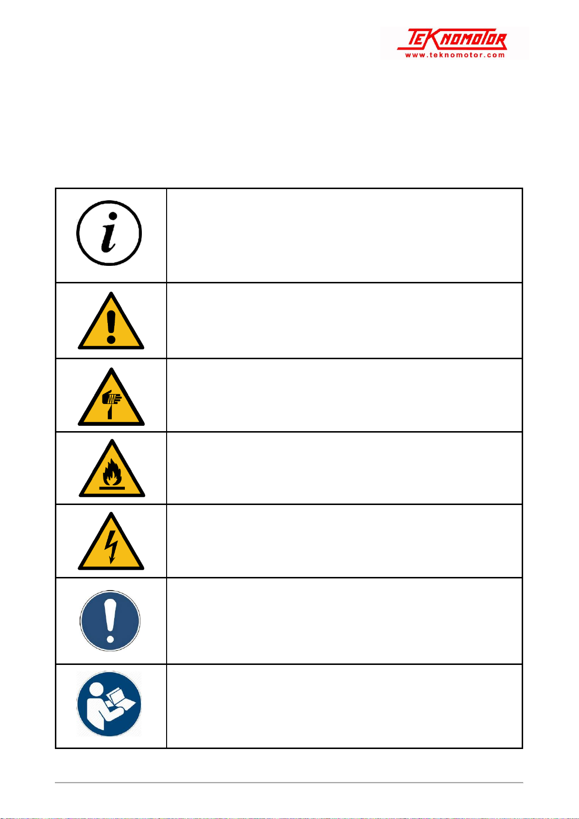
1.1. SYMBOLS AND SAFETY SIGNS USED IN THE MANUAL
This manual highlights important instructions or precautions with the following symbols and safety signs (ref.
ISO 7010):
NOTE: information highlighted by symbols and safety signs is not exhaustive and the whole manual shall be read and applied
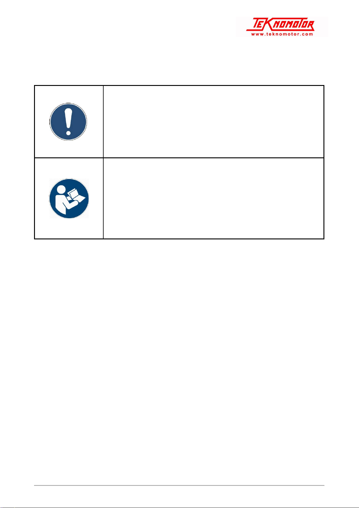
IMPORTANT INFORMATION
GENERAL WARNING IDENTIFIED BY SUPPLEMENTARY SAFETY
INFORMATION
WARNING: SHARP ELEMENT
WARNING: FLAMMABLE MATERIAL
WARNING: ELECTRICITY
GENERAL MANDATORY ACTION IDENTIFIED BY SUPPLEMENTARY
SAFETY INFORMATION
REFER TO INSTRUCTION MANUAL BOOKLET

ATC41-ISO20 INSTRUCTION MANUAL
DOC.U.A.001.DOCX Rev.02 del 11/11/2019 15
DISCONNECT BEFORE CARRYING MAINTENANCE OR REPAIR
1.2. PURPOSE
This user manual contains important instructions and precautions and shall accompany the electrospindle at
all times since it is essential for the safe operation of the electrospindle and operators.
Safety precautions contained herein provide information necessary to ensure the safety of all persons exposed
to the residual risks associated with the electrospindle.
Instructions contained herein provide information necessary for the correct operation of the electrospindle.
Make sure that you read and fully understand all the documentation supplied with the electrospindle to avoid
incorrect operation of the unit and unnecessary risks of personal injury.
Keep this manual easily available in a suitable place near the machine-
Keep this manual safe, and ensure that all persons involved with the electrospindle know of it, fully understand
its contents and have access to it.
IMPORTERS AND DISTRIBUTORS SHALL ENSURE THAT USER MANUAL
ALWAYS ACCOMPANIES THE ELECTROSPINDLE AND THAT CONSUMER,
MACHINE MANUFACTURER AND OTHER END-USERS CAN EASILY FULLY
UNDERSTOOD IT.
USE THE ELECTROSPINDLE ONLY FOR THE PURPOSE FOR WHICH
TEKNOMOTOR S.R.L. DESIGNED IT.
SAFE OPERATION DEPENDS ON THIS.
WARRANTY AND LIABILITY UNDER GENERAL SALE CONDITIONS OF
TEKNOMOTOR DEPEND ON THIS AND THEY WILL LAPSE IF THE
INSTRUCTIONS PROVIDED IN THIS USER MANUAL WILL NOT STRICTLY
APPLIED.
INSTALL THE ELECTROSPINDLES AS DESCRIBED IN THE FOLLOWING
SECTIONS OF THIS MANUAL AND ATTACHED TECHNICAL
DOCUMENTATION.
SAFE OPERATION DEPENDS ON THIS.
WARRANTY AND LIABILITY UNDER GENERAL SALE CONDITIONS OF
TEKNOMOTOR DEPEND ON THIS AND THEY WILL LAPSE IF THE
INSTRUCTIONS PROVIDED IN THIS USER MANUAL WILL NOT STRICTLY
APPLIED.

ATC41-ISO20 INSTRUCTION MANUAL
DOC.U.A.001.DOCX Rev.02 del 11/11/2019 16
2.WARNING AND SAEFTY
PRECAUTIONS
Teknomotor S.r.l. does not and cannot know how end users will install
their electrospindles. The installer or customer must therefore perform
risk assessment specific to each installation and application.
It is also the responsibility of the installer to ensure that adequate guards are provided to prevent accidental
contact with moving parts.
The installer and the operator must also bear in mind other types of risk, particularly those associated with
foreign bodies, explosive, inflammable, toxic or high temperature gasses.
Risks associated with maintenance operations must also be guarded against. Maintenance must be performed
in conditions of maximum safety, and only with the electrospindle fully stationary and switched off.
Once the electrospindle has been installed in the way decided upon by the installer and/or customer, the
machine becomes a “finished machine” as defined for the purposes of the Machinery Directive. Overall risk
assessment must therefore be performed on the finished machine and a declaration of conformity produced
in compliance with Appendix IIA of the 98/37/CE Machinery Directive.
2.1. RISKS ASSOCIATED WITH IMPROPER USE AND HANDLING
▪Never impede the functioning of, remove, modify or in any way interfere with any safety device, guard,
or control of individual parts or of the electrospindle as a whole.
▪Never place your hands, arms, or any other part of your body near moving machinery.
▪Never push objects through the cover grill or into the electrospindle either when it is stationary or when
it is operating.
▪Do not use the electrospindle in atmospheres or environments where there is a risk of explosion.
▪Unless you are duly authorized, never attempt to repair faults or electrospindle malfunctions and never
interfere in any way with the electrospindle operation or installation.
▪On completion of servicing work for which guards, covers, or any other protections have been
removed, always make sure that they have been correctly and securely replaced and are fully
functional before re-starting the electro spindle.
▪Keep all protection and safety devices in perfect working order. Also make sure that all warning and
informative plates, labels and symbols are correctly positioned and perfectly legible.
▪When troubleshooting the electrospindle always adopt all the safety precautions listed in this manual
for the purpose of preventing injury or damage to persons and things.
▪After adjusting any mechanical part, make sure that you fully tighten all screws, bolts or ring nuts you
may have slackened or removed.
▪Before you start the electrospindle, make sure that all the safety devices are installed and perfectly
functional. Do not start the electrospindle if this is not the case, but immediately inform the person
responsible for machine safety or your direct superior.
▪Make sure that you have and use all the personal protective equipment (PPE) required by law. Do not
wear loose or hanging clothing (ties, wide sleeves, etc.).
▪Never use types of tool holder that do not correspond to the models those are specify in this manual;
this cause the risk of breakage or imperfect hook-up of the tool holder cone.
ATC41-ISO20 INSTRUCTION MANUAL
DOC.U.A.001.DOCX Rev.02 del 11/11/2019 17
2.2. RISKS SPECIFIC TO ELECTROSPINDLE MAINTENANCE
▪During all maintenance and cleaning operations, take great care if a tool is fitted. It is advisable to
remove any tool before starting cleaning or maintenance.
▪Disconnect the electrospindle from the main supply before carrying out any maintenance operations.
▪The electrospindle can still turn under the effect of inertia even after it has been switched off. Make
absolutely sure that the electrospindle is not still spinning before starting any maintenance on it.
▪Perform scheduled maintenance as specified in this manual to avoid the risk of mechanical failures
from advanced wear.
NEVER Start any maintenance before making absolutely sure the
electrospindle is stopped spinning.
NEVER Start any maintenance on the electrospindle without first
disconnecting it from the electrical power supply.
NEVER Attempt to clean the electrospindle while it is rotating.
3.GENERAL INFORMATION
3.1. PROPER USE OF ELECTROSPINDLE
Electrospindles designed by TEKNOMOTOR S.R.L. shall operate as part of a machine.
MACHINE DESIGN SHALL CONSIDER THAT FRAME OF THE MACHINE
SHALL WITHSTAND THE WEIGHT OF ELECTROSPINDLE FITTED IN AND
THE STRESSES CAUSED BY TYPE OF MACHINING TO CARRY OUT.
TEKNOMOTOR S.R.L. DESIGNED ELECTROSPINDLE FOR LOW-MEDIUM
POWER MILLING AND DRILLING OF WOOD, FIBERBOARD, PLASTICS AND
ALUMINUM (SEE TO TECHNICAL DATA OF THE SPECIFIC
ELECTROSPINDLE MODEL).
USE THE ELECTROSPINDLE ONLY FOR THE PURPOSE FOR WHICH
TEKNOMOTOR S.R.L. DESIGNED IT.
SAFE OPERATION DEPENDS ON THIS.
ELECTROSPINDLES OPERATE AT S1 DUTY CYCLE UNLESS OTHERWISE
IN TECHNICAL DOCUMENTATION OF THE SPECIFIC MODEL.
CUSTOMER SHALL CARRY OPERATION OF THE ELECTROSPINDLE
ACCORDING TO SERVICE TYPE INDICATED IN TECHNICAL
DOCUMENTATION.
ATC41-ISO20 INSTRUCTION MANUAL
DOC.U.A.001.DOCX Rev.02 del 11/11/2019 18
SERVICE TYPE S1 (standard IEC 60034-1) MEANS OPERATION AT
CONSTANT LOAD WITH A DURATION SUFFICIENT TO ENSURE THAT THE
MOTOR REACHES THERMAL EQUILIBRIUM.
3.2. RANGE OF APPLICATION
The product has been designed to carry out milling and boring operations in the field of wood and its derivates,
plastic, composite material, aluminum and light machining operations on other metals.
The quick replacement of the shaft unit complete with bearings is possible on every models, using the shaft
kit. For further information contact the Teknomotor Technical Office.
All the electrospindles have a mechanical reaction system that almost completely cancels the axial force of
the pistons on the bearing during the tool changing phase. It guarantees the long life of the front precision
bearings.
ATC41-ISO20 INSTRUCTION MANUAL
DOC.U.A.001.DOCX Rev.02 del 11/11/2019 19
4.TECHNICAL SPECIFICATIONS
4.1. THE MAIN PARTS OF THE ELECTROSPINDLE
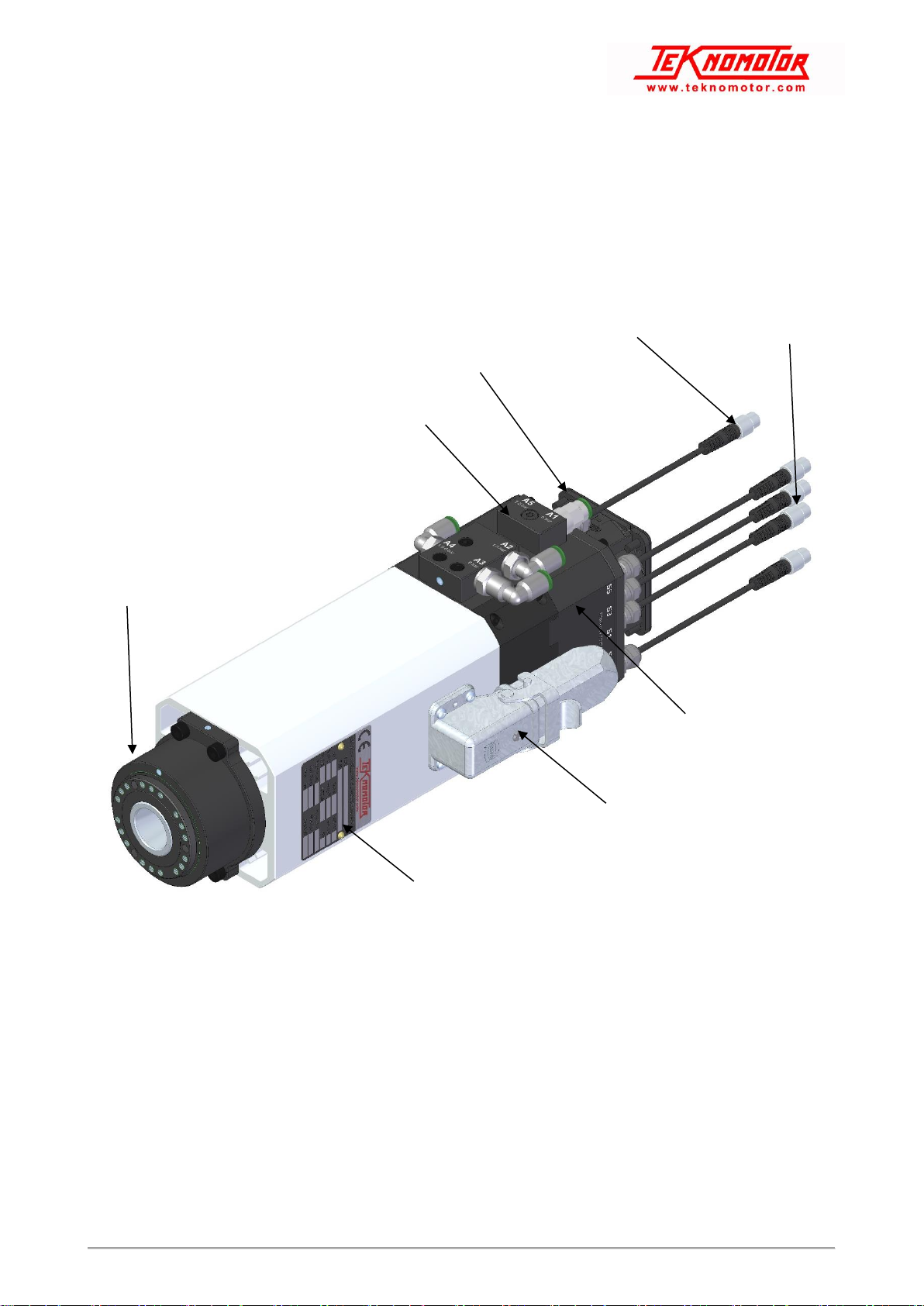
Figure 1 Main part of the electrospindle
MOTOR NAMEPLATE
COMPRESSED AIR CONNECTORS
ELECTRIC FAN
POWER CONNECTOR
SIGNAL CONNECTOR
SENSORS CARTER
NOSE PRESSURIZATION
ELECTRIC FAN
CONNECTOR
ATC41-ISO20 INSTRUCTION MANUAL
DOC.U.A.001.DOCX Rev.02 del 11/11/2019 20
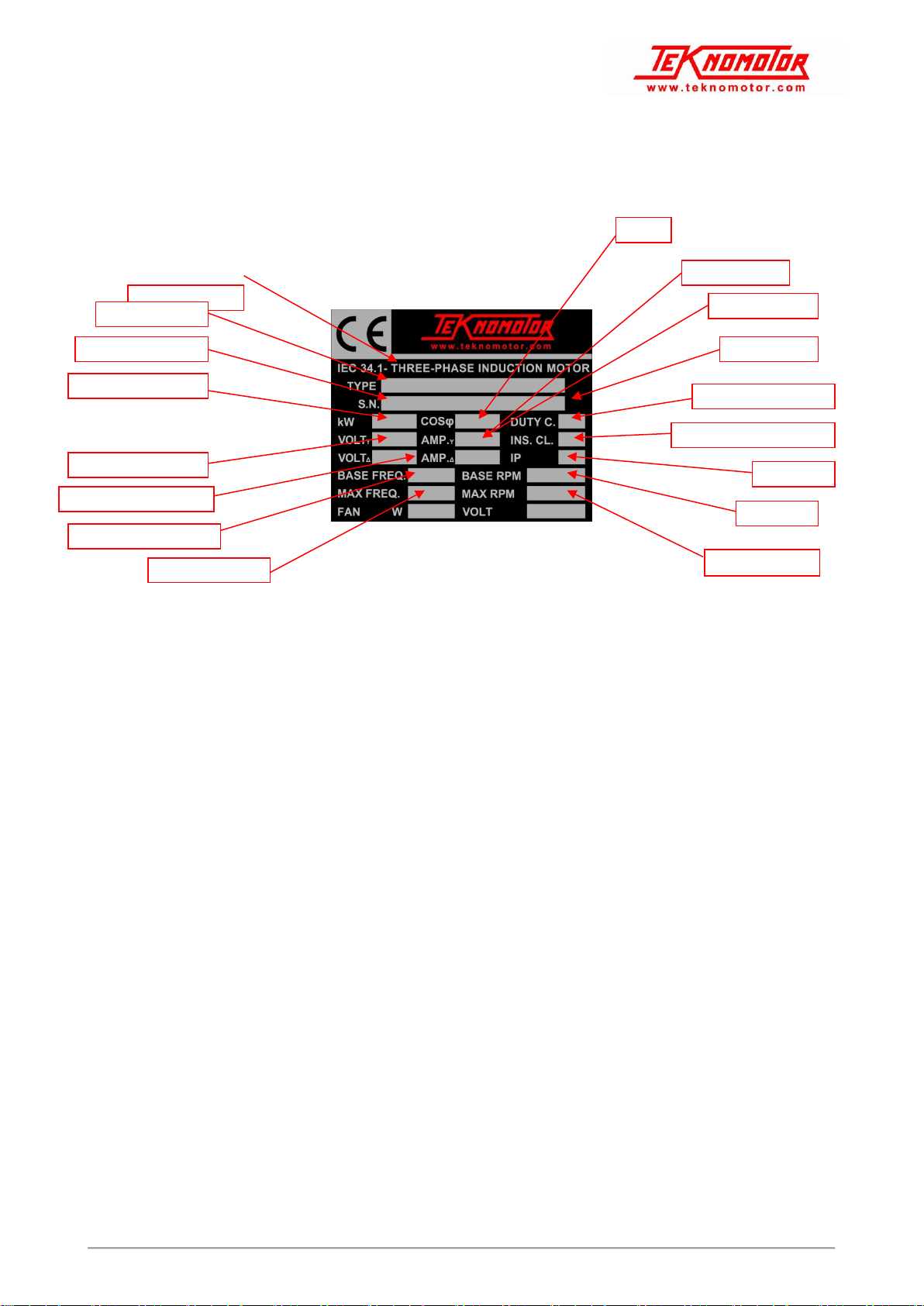
4.2. IDENTIFYNG THE MOTOR DATA FROM THE NAME PLATE
The part number (P.N. or TYPE) and the serial number (S.N.) are printed on the name plate and they are only
way to identify the electrospindle recognized by the manufacturer. For this reason they must be kept legible
throughout the unit’s working life. The place of the name plate and the disposition of data in the name plate
could be different model by model.
Figure 2 Typical Teknomotor electrospindle nameplate
4.3. GENERAL VIEWS, OVERALL DIMENSIONS AND PERFORMANCE
See attached documents. If the document is not available please contact Teknomotor technical office.
PART NUMBER
SERIAL NUMBER
MOTOR POWER [kW]
BASE VOLTAGE Y [V]
BASE VOLTAGE Δ [V]
SE
BASE FREQUENCY [Hz]
]BASE
MAX FREQUENCY [Hz]
FAN POWER [W]
CURRENT Δ [A]
CURRENT Y [A]
DUTY CYCLE
INSULATION CLASS
COSφ
INSULATION PROTECTION
BASE RPM
MAX RPM
FAN SUPPLY [V]
ATC41-ISO20 INSTRUCTION MANUAL
DOC.U.A.001.DOCX Rev.02 del 11/11/2019 21
5.TRASPORT, PACKAGING,
UNPACKAGING AND STORAGE
5.1. PACKAGING AND LIFTING
▪Lifting and moving the electrospindle can create situations of risk to persons nearby. Always follow the
instructions provided by this manual, follow all possible safety instruction for the handling of heavy
loads. Always use suitable lifting equipment. The responsibility for the safety of the people involved in
handling, moving and lifting operation is of the customer.
▪Installation and assembly work must be performed only by specialist technicians.
▪Always use great care in lifting and moving electrospindles and their components. Avoid impacts which
can damage the body or the shaft or the bearings of the electrospindle.
It is the responsibility of the customer to ensure that the lifting
equipment used is suitable for the purpose in terms of functioning and
load capacity.
Never lift the electrospindle by its fan cover. This can break, damaging
the electrospindle and possibly causing personal injury.
Never drill parts of electrospindle to attach elements useful to move
electrospindle.
Load characteristics
The load is to be considered too heavy for a single person when:
•It weights for more than 30 kg for men
•It weights for more than 20 kg for women
Do not drill the electrospindle to fit any hoisting tool.
5.2. STORAGE
If the electrospindle is to be stored for any length of time, make sure that it is protected against the elements
and in particular against damp, dust, and other forms of damage by the atmosphere or storage environment.
STORAGE TEMPERATURE: from -5°C to +55°C
NON-CONDENSING RELATIVE HUMIDITY: from 5% to 15%
The storage time of Teknomotor electrospindle is 12 months. After
this time-limit the product must be inspected by an authorized
Teknomotor service. If you need more information please contact
Teknomotor S.r.l..
Table of contents
Other Teknomotor Industrial Equipment manuals


