GMP 89004 Troubleshooting guide

Page 1 of 36 General Machine Products (KT), LLC
89004 – USA
POWERED DUCT ROD PUSHER
Copyright 2017 by General Machine (KT), LLC
All rights reserved. No part of this publication may be copied, reproduced or transmitted in any form
whatsoever without the written permission of General Machine Products (KT), LLC
POWERED DUCT ROD PUSHER
OPERATION & MAINTENANCE
GMP • 3111 Old Lincoln Hwy • Trevose, PA 19053 • USA
TEL: +1-215-357-5500 • FAX: +1-215-357-6216 • EMAIL: info@gmptools.com
QC Final Inspection by:_________________________ Date:__________________
Unit Serial Number:__________________
Build Date:__________________
July 12 2017 USA Ver 3a
Manual P/N 32297

Page 2 of 36 General Machine Products (KT), LLC
Rev # Date Details Author
01 07.27.05 Original issue A. Sibun
02 10.16.08 US Version 1 A. Konschak
REVISION HISTORY
03 05.26.09 US Version 2 A. Konschak
04 08.29.09 US Version 3 A. Konschak
05 07.12.17 US Version 3a - Changed Company Name A. Konschak
GMP product warranty can be found at http://www.gmptools.com/warranty/

Page 3 of 36 General Machine Products (KT), LLC
CONTENTS
1. Safety Instructions
2. Critical Points
3. General Description
4. Specification
5. Operating procedures
6. Maintenance
7. Procedure for Replacement of Chain Drives
8. Procedure for Replacement of sub-duct clamp collets
9. Procedure for Adjusting the sub duct clamp and collet type rod infeed guide assembly height
10. Monthly Service – Check List
11. Service History Record
12. Troubleshooting Guide
13. Recommended Spares List
APPENDICES
Appendix 1 Layout of Rod Pushing Machine
Appendix 2 Drawing – Rod Pushing Machine
Appendix 3 Hydraulic & Electrical Panel Layout
Appendix 4 Counter programming parameters
Warranty

Page 4 of 36 General Machine Products (KT), LLC
Founded by engineer George M. Pfundt in 1936, GMP started op-
erations in a downtown Philadelphia building as a specialty ma-
chine shop doing work for the local Bell Telephone company and
for the electric utility company. GMP expanded to a production
shop after landing a contract
with Western Electric Compa-
ny and, subsequently, forming
a close relationship with Bell Telephone Laborato-
ries in Murray Hill, N.J., which enabled it to manu-
facture prototypes of products for experimental
use within the Bell System.
Having outgrown the original factory building, the
company built a 100,000 square foot plant in Tre-
vose, PA (a Philadelphia suburb) and moved there
in 1957. Today GMP is recognized as a premier
worldwide supplier of specialty tools and equip-
ment for the outside plant marketplace. The company's products are known for their
robust design and durability to withstand many years of frequent use.
INTRODUCTION

Page 5 of 36 General Machine Products (KT), LLC
1. SAFETY INSTRUCTIONS
WORK AREA AND GENERAL SAFETY
1. Read and understand the operation and maintenance manual supplied with this equip-
ment. Keep it in a convenient place for future reference.
2. Keep children and untrained personnel away from this equipment while in operation.
3. Keep all guards and safety devices in place. Do not operate this equipment with guards
removed or damaged.
4. Keep hands, feet and loose clothing away from moving parts, especially at cable entry
points.
5. Always stop the machine and isolate hydraulic and electrical services to carry out lubrica-
tion and servicing.
6. Check machine before starting for worn or damaged parts. Check for signs of loose nuts
and bolts etc.
7. If machine is left unattended, insure that unauthorized use is prevented.
8. Never leave the machine unattended while in use.
9. Consider the use of safety barriers, especially when used in public places, observe all
statutory requirements for working environments.
10. Beware of pinch points involved with rotating components.
11. Beware of hot surfaces, machine uses hydraulics.
12. When operating machine always wear eye protection, hard hat, safety shoes and leather
gloves, machine operates with hydraulic oil at 2030 psi.
This Equipment should be used only by personnel who have been given the appropri-
ate training and who are competent to use it.
These instructions are to be made available to operators of this equipment at all times.
Failure to observe these safety instructions could result in serious personal injury and/
or property damage.
CAUTION:
This machine is designed to work with one piece, continuous rod with no breaks. Rods that
have been repaired and have a coupling at any point along its length, cannot be used since
the coupling cannot safely pass through the Duct Rod Pusher.
!
FAILURE TO DO SO MAY RESULT IN PERSONAL INJURY

Page 6 of 36 General Machine Products (KT), LLC
13. Some component and assembly parts are in excess of 55 lbs. (25kg) . When lifting care must
be taken, insure sufficient man power/lifting gear is available, to prevent personal injury and
damage to the machine. Beware of exposed electrical contacts. Do not touch, or allow
metal objects to come into contact.
14. Prior to installation insure the sub-duct route is connected properly.
15. Beware of exposed electrical contacts. Do not touch. Or allow metal objects to come into
contact. Waste hydraulic oils are to be disposed of via an environmentally acceptable
method.
16. Wear hearing protection when noise level are above acceptable limits. To reduce noise,
position Power Pack away from user.
17. Machine may cause additional fire hazard if involved in an existing fire due to hydraulic
oils.
18. No personnel are to be in manholes or ducts when the duct rod pusher is in operation.
19. The machine must be operated on firm ground.
20. Stay clear of rods or lines under tension.
21. Only use the machine for its intended purpose.
22. Do not place duct rod carrier too close to the powered duct rodder.
23. Do not tamper with pressure relief valves or pressure reducing valves.
24. Never operate the rod pushing machine with the electronic control panel immersed in wa-
ter.
25. To prevent damage to the hydraulic hoses and the emergency stop cable never leave
them on the ground when not in use.

Page 7 of 36 General Machine Products (KT), LLC
GENERAL HYDRAULICS SAFETY INSTRUCTIONS
Escaping fluids under pressure can penetrate the skin and cause serious personal injury. Ob-
serve the following precautions to avoid hydraulic hazards: -
1. Insure all hydraulic connections are securely tightened before operating the machine.
2. Check for leaks with a piece of cardboard. Do not use your hands!
3. Do not exceed working pressure of hydraulic hoses.
4. Visually inspect hoses regularly and replace if damaged.
GENERAL ELECTRICAL SAFETY INSTRUCTIONS
The machine has electronic and electrical power and control circuits. Electric shock hazards
exist that could result in severe personal injury. Observe the following precautions to avoid
electrical hazards:
1. Do not operate in water.
2. Do not expose the machine to rain.
3. Do not remove cover of electronic control assembly.
There are no user serviceable parts inside.
4. Refer servicing to qualified service personnel.

Page 8 of 36 General Machine Products (KT), LLC
a. Two (2) turns on the rod clamping screw.
b. Tractor drive to be closed at all times when rod is installed into machine.
c. Sub-Duct clamp height adjustment correctly set.
d. Rod in-feed bracket height adjustment correctly set.
e. Sub-duct fully connected.
f. Rod drum must be located directly behind and in line with the pushing machine.
g. Sub-duct clamp, tractor drive belts/chains, housing framed and rod guide intake assembly must be
clean and free from debris, sludge, dirt, water and lubricant. (Each time the pushing machine is
used.)
h. The hydraulic pressure should be between 290-580 PSI at the start of an installation. If greater do
not proceed. Check rod clamping screw setting, sub-duct, rod, rod collet sizes, sub-duct clamp/in-
feed guide height setting. Rectify before re-commencing the installation.
i. Lubricate the drive chains before use.
j. Do not repeatedly press the on/off button on the length/speed readout. This may result in irrelevant
digits being displayed or may alter the program. Always fit the hydraulic hose dust caps when the
hose is not in use, clean and check the quick release couplings before use.
2. CRITICAL POINTS THAT DRAMATICALLY AFFECT THE
OPERATION OF THE ROD PUSHING MACHINE
NOTE:
This machine is primarily designed to work with the GMP 1/2 Duct Rodder. Other manufacturer’s Duct
Rodders may be able to be modified to work. Please contact the factory for details.

Page 9 of 36 General Machine Products (KT), LLC
3. GENERAL DESCRIPTION
The Duct Rod Pushing machine has been designed to provide an effective and safe method
of rod installation and removal. The system installs rod of 1/2” overall diameter at up to 130 ft/
min into pre-installed sub-ducts.
The machine is protected by preset pressure relief valve and preset pressure sensor.
The hydraulically powered rod feed system controls the rod. The electronic control system
displays speed, distance, direction and the preset pressure sensor provides automatic protec-
tion against duct obstruction.
The system comes mounted on a sturdy anti-corrosion, height adjustable, wheeled, tubular
steel trolley unit for ease of site maneuverability, and is powered by a hydraulic supply system
operating at 2030 psi x 5.3 gallons/min.
The rod pushing unit can be easily detached from the trolley and located in a trench or man-
hole (depending on the size of the manhole).
The unit is supplied with two (2) x hydraulic hoses x 23 feet and a 26 foot long emergency
stop lead.

Page 10 of 36 General Machine Products (KT), LLC
FEATURES
Fully labeled control panel containing:
▪ Power ON/OFF button
▪ Emergency Stop Button
▪ Installation speed and direction readout in m/min or ft/min through a separate calibraon
▪ Length counter tracking in feet or meters through a separate calibraon
▪ Hydraulic pressure display gauge
▪ Hydraulic on/off control valve
▪ Emergency stop connection socket
▪ Adjustable speed control for drive belts
▪ Battery Charging Connection
Control panels are anti corrosion treated and may be removed independently for repair work.
CHASSIS
▪ Front mounted wheels for ease of maneuverability
▪ Light painted tubular steel frame
▪ Adjustable frame allowing unit to be tilted at 20º to manhole
▪ Adjustable legs for uneven terrain
▪ Detachable rod pushing unit for trench / manhole location
ROD FEEDER
▪ Manufactured from cast aluminum
▪ Hydraulically powered
▪ Unit lifts and splits to allow insertion of rod between drive belts
▪ Drive belts are polyurethane and molded to unit ensuring long life between replacements.
▪ Lifting hook built into adjustable jack screw to allow unit level lift.
▪ Belt tension can be set by means of adjustable chain drive tensioners fitted to the side of
the unit
▪ System relief valve factory set to 1500 psi.

Page 11 of 36 General Machine Products (KT), LLC
4. SPECIFICATIONS
OPERATION CAPACITIES
Pushing Force 0-300 lbs. (0 - 136 kg)
Pushing Speed 0-130 ft/min (0 - 40m/m)
Rod Size 1/2” (12.7mm)
Sub-Duct Size 1-1/4 SDR
HYDRAULIC DRIVE SYSTEM
Operating Pressure 2030 psi (max) (110 Bar)
Flow 5.3 gallons/min (recommended)
Pressure Switch Setting 1450 psi (100 Bar)
Relief Valve Setting 1500 psi (103 Bar)
Initial starting pressure 290-580 psi (20-40 Bar) (if greater the set-up
needs checking)
ELECTRONIC CONTROL SYSTEM
Power requirements: 12 Volts DC
Fuse Rating 3.15 amp (Slow-Blow)
DIMENSION AND WEIGHTS
Height 49”
Length 42”
Width 28”
Weight 210 lbs.
Tire Size 3.00-4/260x85
Drive Chain Lubrication Metaflux 70-88 Chain Spray
Tire Pressure 25 psi (1.72 Bar)

Page 12 of 36 General Machine Products (KT), LLC
5. OPERATING PROCEDURE
It is imperative that all persons using, operation or maintaining this cable blowing ma-
chine:
Have received comprehensive training in the use of this machine.
Are competent and authorized to use it and have read and understand this manual.
General Machine Products (KT), LLC cannot be held responsible for misuse of this
equipment.
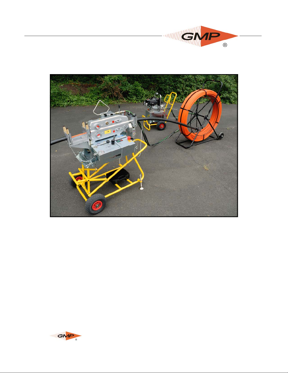
1. Position the Rod Pushing Machine in a suitable position in line with
the proposed sub-duct.
2. Adjust the mounting frame to the desired height and angle by means of the front frame sup-
ports. Withdraw the front ‘R’ clip and retaining pin while supporting the weight of the rod
pushing unit. Raise or lower the pushing unit and locate onto the support bar for the desired
position. Refit the retaining pin and ‘R’ clip. Alternatively the pushing unit may be detached
from the trolley frame by withdrawing both ‘R’ clips and retaining pins, while supporting the
weight of the pushing unit.
3. Stabilize the frame on uneven ground by adjusting the height on the pivoting feet at the rear
of the unit and locking in position.
NOTE: CARE SHOULD BE TAKEN WHEN WHEELING THE TROLLEY AROUND NOT TO
CATCH THE ADJUSTABLE FEET PADS ON CURBS OR BOULDERS, THIS MAY DAM-
AGE THE PIVOTING FOOT.
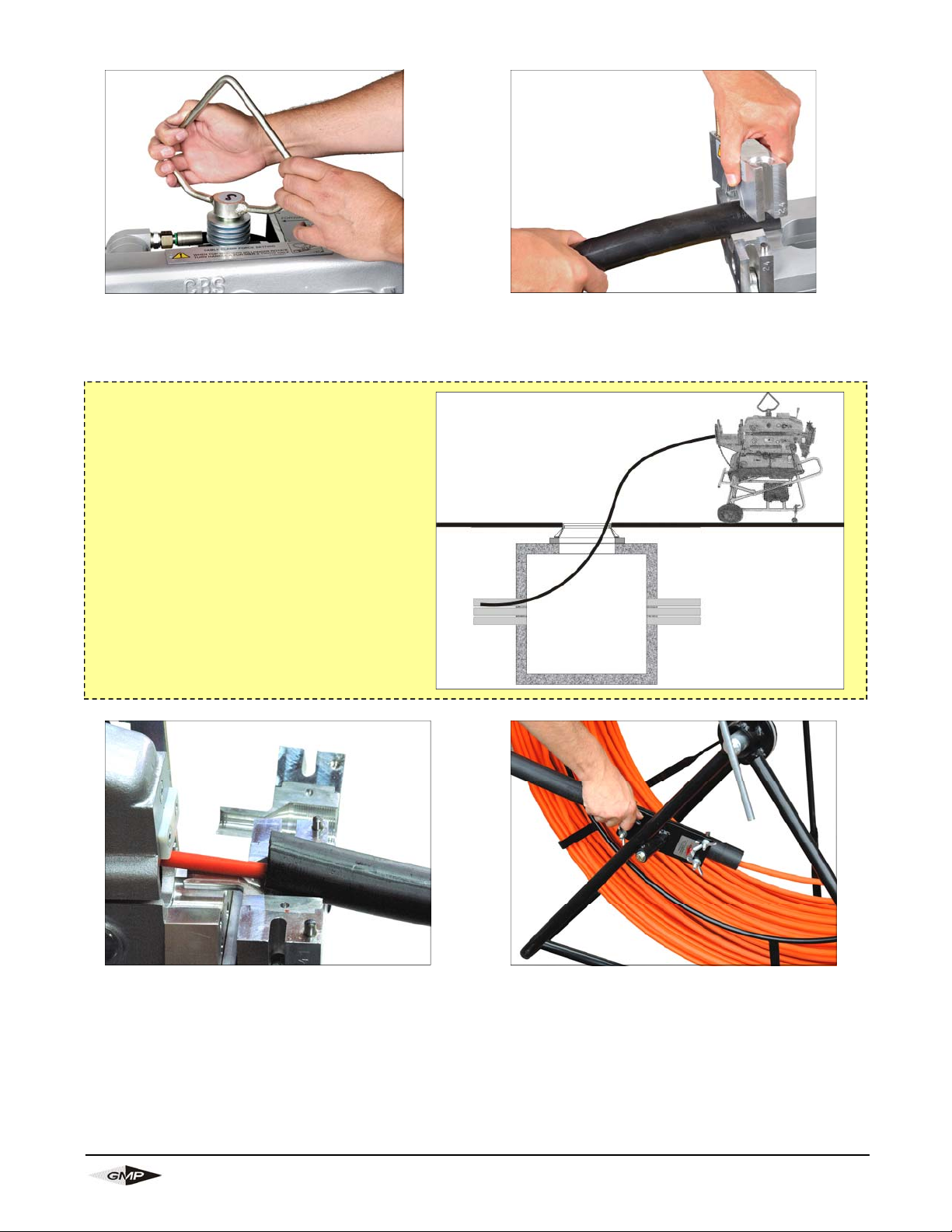
4. Position Duct Rod approximately 5’ behind the Duct Rod Pusher at about a 35° angle.
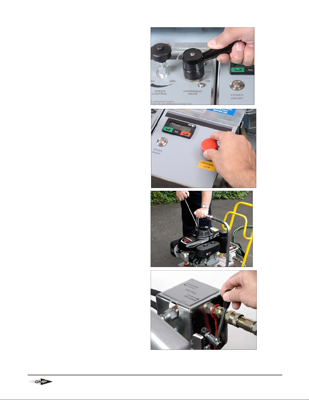
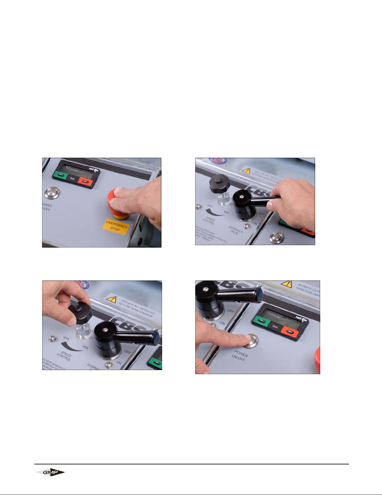
5. Insure the battery is fully charged before commencement of installation.
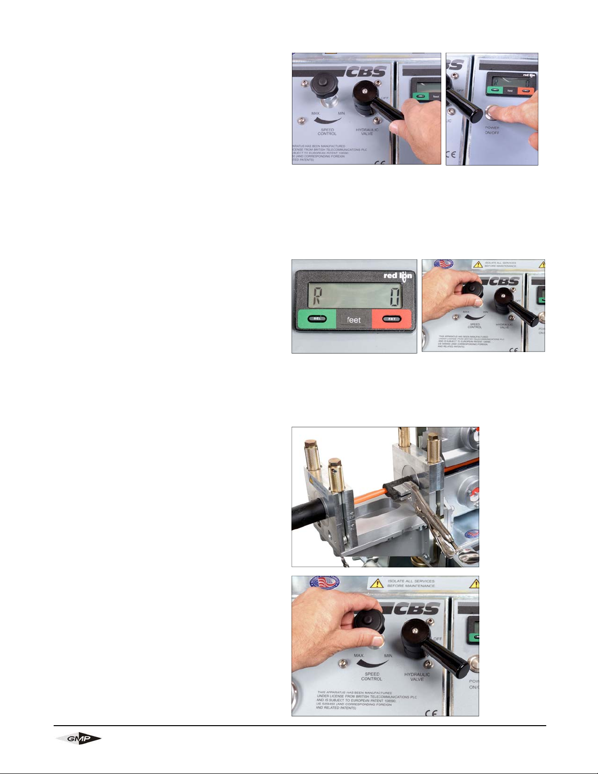
6. Open tractor drive.
CLEAN ANY DEBRIS, SLUDGE, DIRT, WATER, LUBRICANT,
ETC, FROM FRAME HOUSINGS AND ROD INTAKE GUIDE
BRACKET ASSEMBLY EACH TIME BEFORE USE.
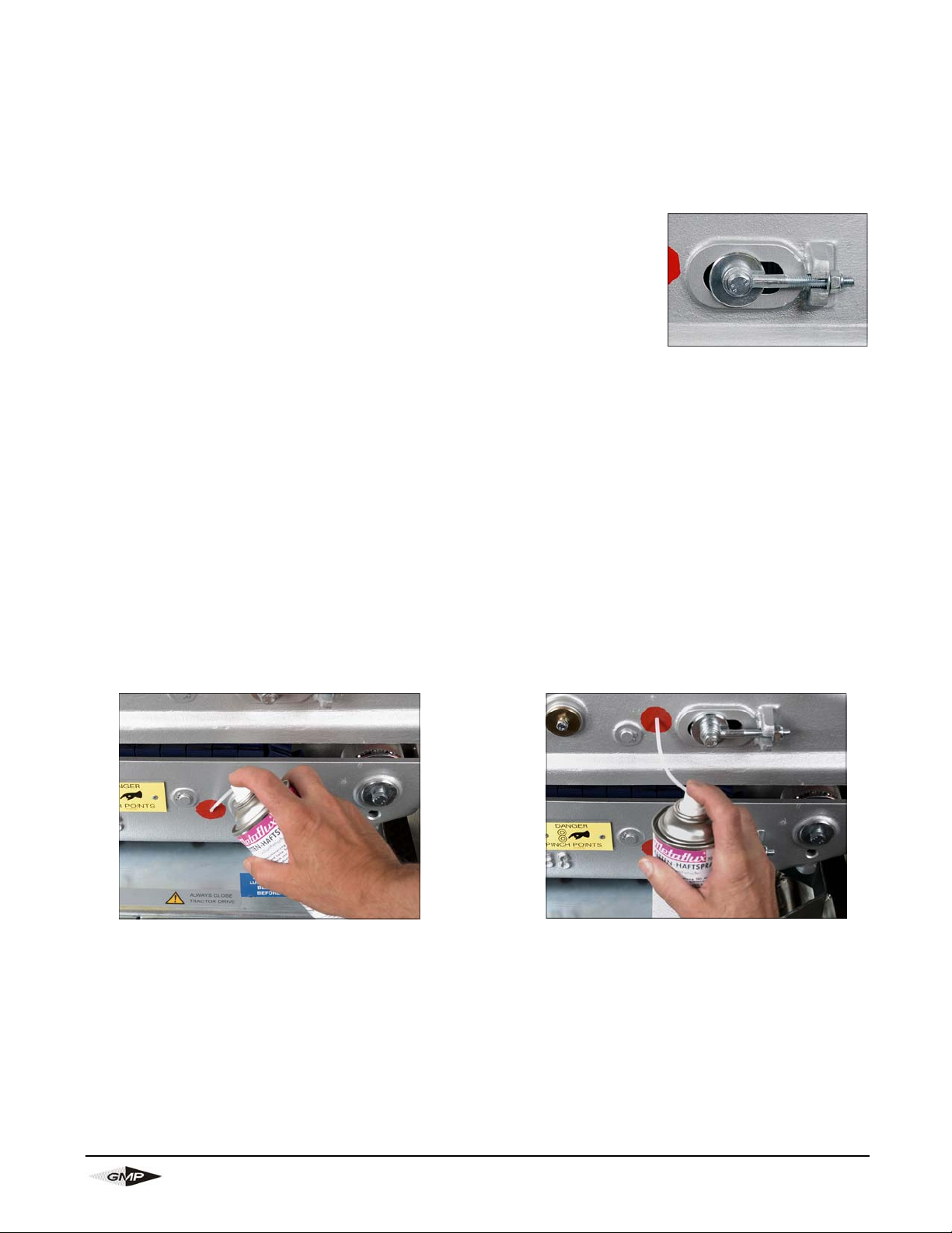
LUBRICATE BOTH CHAINS BEFORE USE.
CLEAN BOTH TRACTOR DRIVE BELTS BE-
FORE USE.
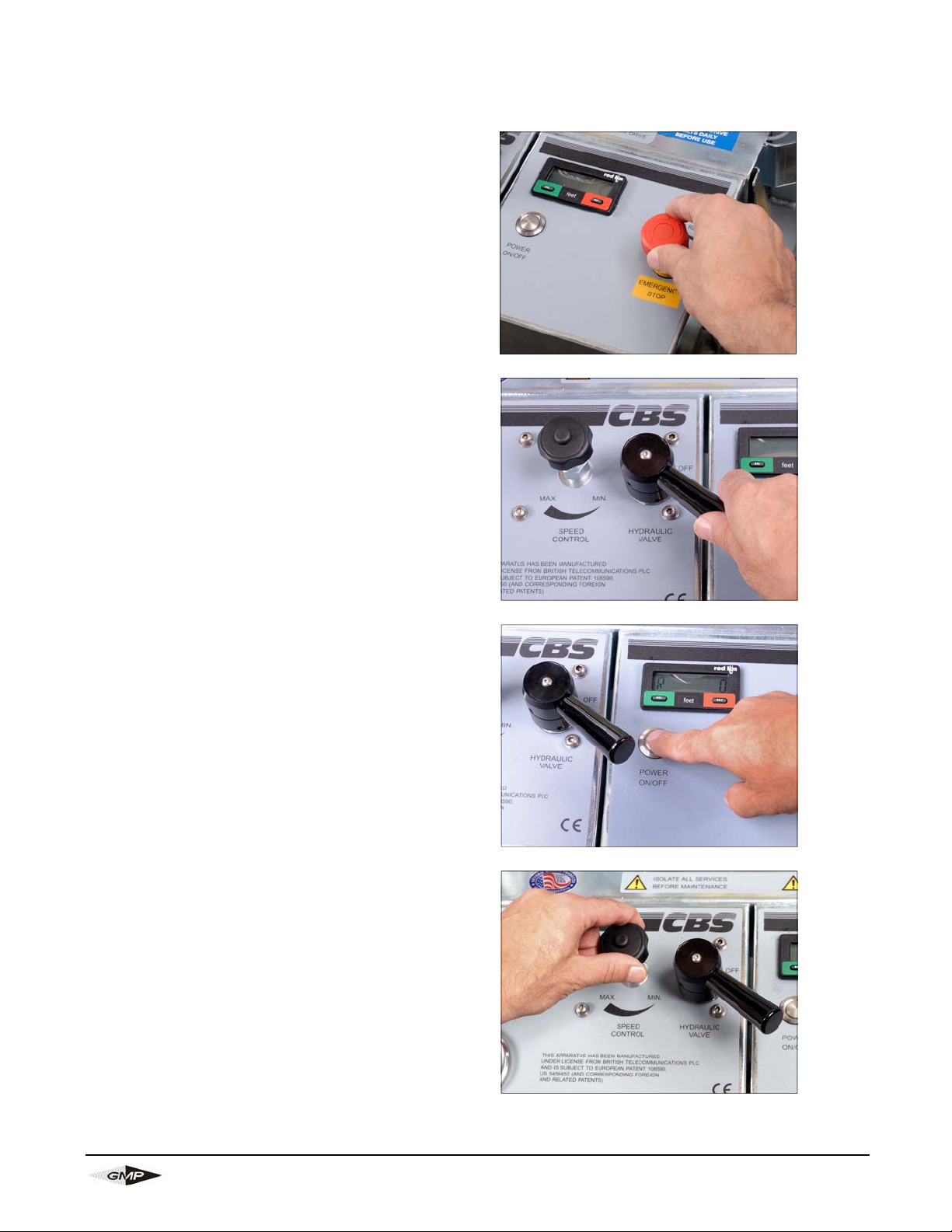
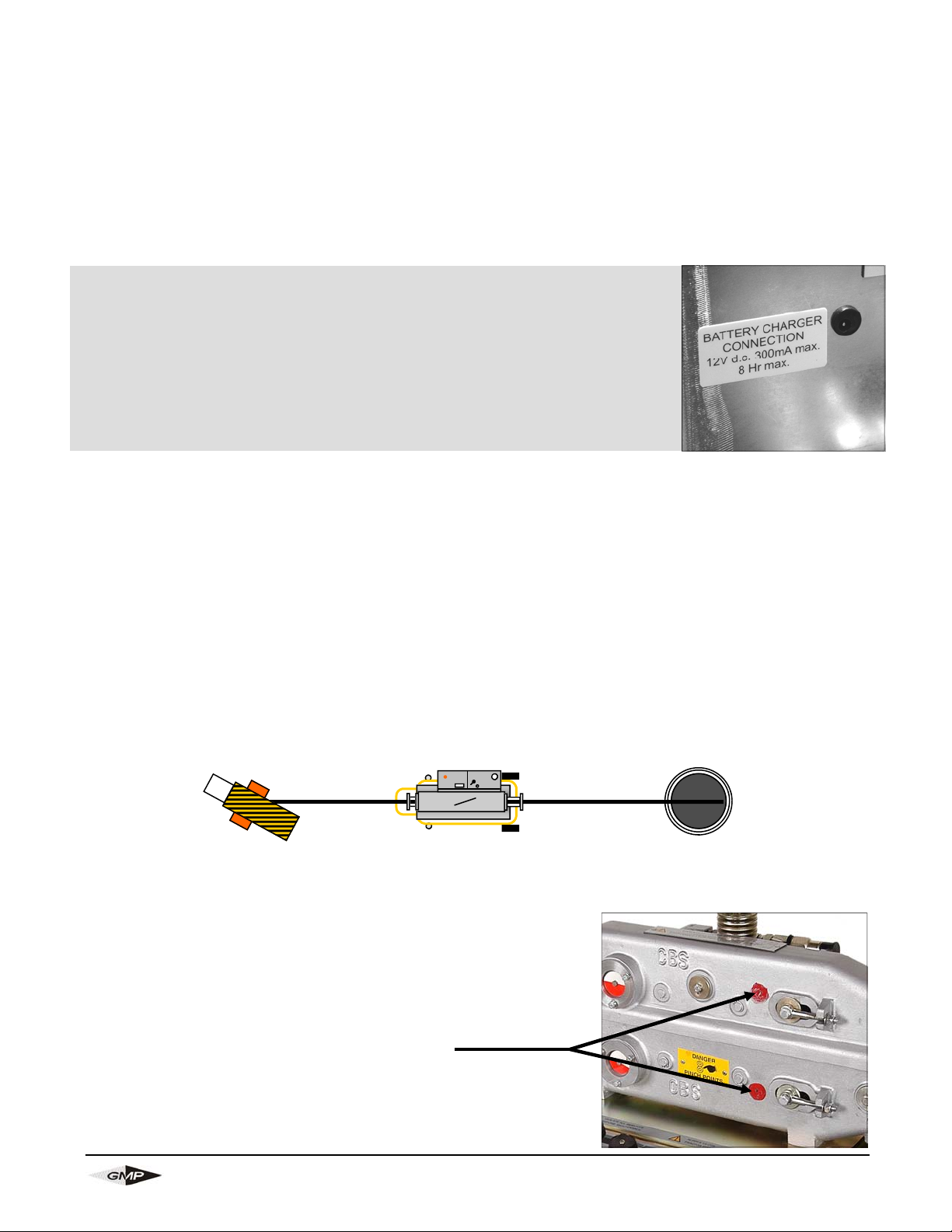
Charging the 12 volt battery before use:
Plug in the supplied battery charger in the charging jack found on the
right of the control panel. Initially charge the battery for 8 hours before
use (to approximately 13 volts). Continuous charging of the battery with
your charger will reduce the life of the battery. Remove the charger
when charging is complete. When voltage dips to 12 volts, recharge the
battery. Optimize battery life by turning off the display when not in use.
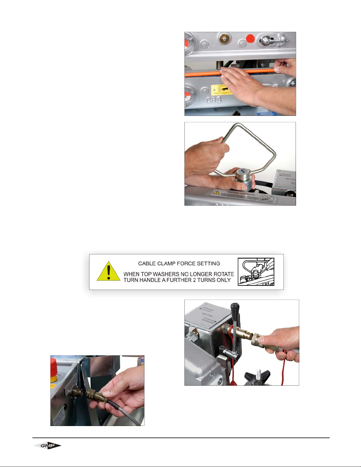
Lubrication Points
Duct Rod
Duct Rod Pusher
5ft 1 1/4” Duct 1 1/4” Duct

Page 13 of 36 General Machine Products (KT), LLC
7. Open tractor drive enough to feed the
duct rod through the pusher.
8. Place sub-duct from the manhole into out
-feed sub-duct clamp and tighten with
3/4” wrench (provided).
9. Take a 5’ piece (approx) of 1-1/4 sub-
duct and lay it into the opened infeed
sub-duct clamp. Feed the rod thru the
duct so that it’s about a foot into the
duct rodder, ensuring that the con-
nector on the end of the rod is past
the infeed clamp. Now tighten the
clamp on the duct.
10. Clamp the other end of the 1 1/4” sub-
duct into the supplied duct rodder car-
riage clamp.
TIP:
If the duct that is to be rodded is larger
than 1 1/4”, insert a piece of 1 1/4 sub-
duct from the out-feed of the Duct Rod-
der into the larger duct causing the
smaller duct to act like a feeder.
Tie off the small duct to a ladder or some
other permanent fixture if possible. This
prevents the sub-duct from kicking back
should the duct rod encounter and ob-
struction.

Page 14 of 36 General Machine Products (KT), LLC
11. Feed the duct rod through the
pusher and into the sub-duct that’s
placed in the manhole.
12. The correct rod clamping force is
vital to the performance of the ma-
chine. It should be set as follows:
Tighten the handle with one hand
rotating the clamp washers with
the other. The clamp washers will
turn easily until the handle begins
to clamp them. When the clamp
washers become almost impossi-
ble to turn with one hand, this is
the start point for the clamp force
setting. Continue to turn the handle
a further 2 full turns. This will in-
sure the correct force.
13. Connect the hydraulic hoses
and emergency stop connector to
the duct rod pusher taking note
that the connector is female on the
pusher side and male on the power
pack side.

Page 15 of 36 General Machine Products (KT), LLC
14. Insure that the hydraulic control
lever is in the “OFF” position and
the speed control knob is in the
“Min” position (fully rotated coun-
ter-clockwise).
15. The emergency stop button is set
to on (upper most position). If not
set, twist counter-clockwise to re-
set.
16. Start the engine on the power
pack. Insure that you have
enough fuel for the duration of the
pushing operation.
17. Select desired pushing direction
from the valve to the rear of the
machine. Direction is indicated.

Page 16 of 36 General Machine Products (KT), LLC
18. Turn the Hydraulic lever valve to
the “ON” position.
20. Turn the speed control valve
clockwise (towards ‘max’) until the
desired speed (130 ft/min max) is
achieved.
21. Continue to install rod into sub-duct. The operator wearing work gloves should insure the
rod enters the machine without debris. Care must be taken to avoid injury by clothing or
fingers being dragged into the machine. Failure to do so may result in damage to the rod
form the drive belts and/or jamming of the rod.
23. On completion screw the speed
control knob to the min to stop the
machine, (counter clockwise),
press the reset button and select
neutral from the direction control
valve.
19. Turn on the digital display by pressing the “power on/off” button. Allow approx. five
(5) seconds for the display to appear. Pressing SEL toggles between installation dis-
tance (ft) and speed (ft/min) (designated by R). Pressing RST will reset the distance
reading to zero (0).
24. To prevent dirt from entering the
machine when pulling back the
rod, use a felt wiper at the sub-
duct out feed side and clamp it
tightly to the rod as shown in pho-
to.

Page 17 of 36 General Machine Products (KT), LLC
IN THE EVENT OF AN EMERGENCY
1. Push the emergency stop push button. 2. Turn the hydraulic valve to the ‘off’ position.
3. Turn the speed control knob to “Min”
position (fully counter clockwise)
4. Press the on/off button (to turn off the
electric’s off, if required).
24. IF THE PUSHING MACHINE STOPS SUDDENLY
If the rod pushing machine stops suddenly during the pushing operation it is likely that
the pressure switch has tripped, the probable reasons for this are: -
A) The rod has become jammed, has hit an obstruction in the duct or the rod pushing
operation has reached its maximum capability.
B) The power pack has developed a problem or has run out of fuel.

Page 18 of 36 General Machine Products (KT), LLC
TO RESTART
1. Take machine out of emergency stop by
turning the red button counter clock wise.
Restart the hydraulic power pack.
2. Turn the hydraulic on/off valve to “on’”
position.
3. Turn on the digital display by pressing
the “power on/off” button. (If the electric’s
have been switched off)
4. Turn the speed control valve clockwise
until the desired speed (up to 130 ft/min
max) is achieved.

Page 19 of 36 General Machine Products (KT), LLC
6. MAINTENANCE
To insure reliable service from your Rod Pushing Machine, we recommend the unit be com-
pletely serviced every 6 months.
TRACTOR DRIVE
Inspect the chain drive blocks for wear each week.
CHECK the chain tension weekly and adjust if necessary with the two
external adjustment screws (do not over tension). The chain should
slightly lift off the chain guides, when pulled at the center by finger.
THE CHAIN SHOULD BE LUBRICATED EACH TIME USED by ap-
plication of Metaflux
spray grease 70-88. This is achieved by running the rod pushing machine at about 130ft/min
without any rod and carefully inserting the spray tube from the canister into the holes on the
operator side of the aluminum drive castings (2). The spray tube should be carefully inserted
until the chain can just be felt and then withdrawn about 3/4 – 1” and spraying for approxi-
mately 1 second.
DO NOT OVER LUBRICATE, AS THIS MAY LEAD TO THE DRIVE BELTS BEING
CONTAMINATED WITH LUBRICANT.
If contamination does result, wipe the belts clean thoroughly before attempting any pushing
operation. (This is based on normal use where the chains are not exposed to excessive
contamination).
Bottom frame chain lubrication
point
Top frame chain lubrication point

Page 20 of 36 General Machine Products (KT), LLC
GENERAL
The machine should be stored under cover when not in use. The machine should be wiped
clean after each time used.
ALWAYS insure that the service battery and spare battery (if available) are fully charged,
before this rod-pushing machine is to be used. The machine uses a conventional lead – acid
batterie, this may be charged using the supplied battery charger for a maximum of 8 hours.
CHECK the tire pressures and tire condition weekly. Oil the frame pivot points and lubricate
the oilite bearings with light machine oil every month. Apply grease to the jacking screw
thread each month clean out any dirt/debris from the rod-measuring wheel, measuring disc
and speed pick up probe.
Oil sub duct clamp adjusting screw and rod infeed guide adjusting screw monthly.
Grease axles every month. Check function of electrical panel each time.
SERVICE CONNECTIONS
CHECK the condition of the hydraulic hoses each time used and replace if worn or damaged.
CHECK the condition of the emergency stop cable each time used and replace if worn or
damaged.
Table of contents
Other GMP Industrial Equipment manuals