Konecranes DMCS022 User manual

DMCS022 Upgrade Kit
Installation Instruction
020145en / Revision D / 2015-04-29
Original Instruction
This document and the information contained herein, is the exclusive property of Konecranes Plc. and represents a non-public, confidential and proprietary
trade secret that may not be reproduced, disclosed to other parties, altered or otherwise employed in any manner whatsoever without the express written
consent of Konecranes Plc. Copyright © (2014) Konecranes Plc. All rights reserved.

TABLE OF CONTENTS
1 INTRODUCTION................................................................................................................................... 3
1.1 About this manual......................................................................................................................... 3
1.2 About the upgrade kit usage......................................................................................................... 3
1.3 Waste treatment and recycling of removed material...................................................................... 3
2SAFETY................................................................................................................................................. 4
2.1 Before starting to work at the site.................................................................................................. 4
2.2 Main switch and emergency stop buttons...................................................................................... 4
2.3 After working at the site................................................................................................................. 4
3DESCRIPTION OF THE UPGRADE KIT............................................................................................... 5
3.1 Parts included in the kit................................................................................................................. 5
3.2 Required tools............................................................................................................................... 6
3.3 Terminal connections.................................................................................................................... 7
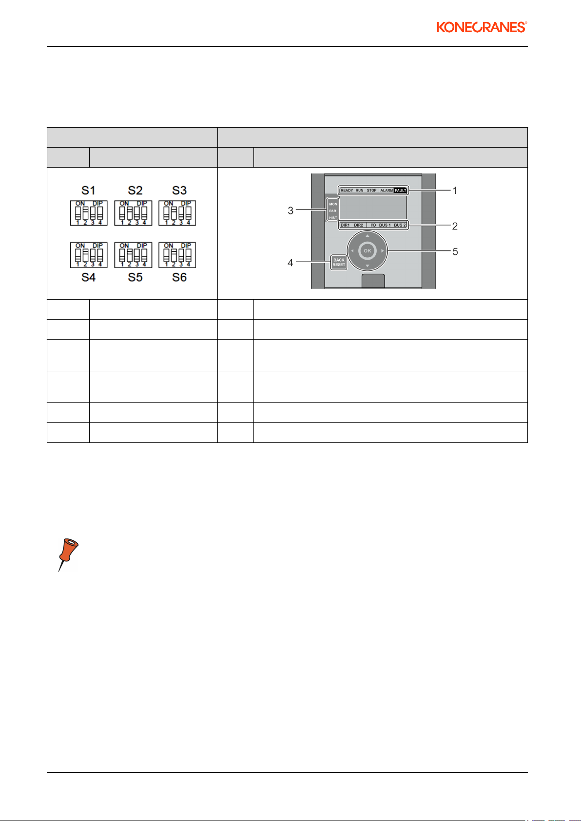
3.4 User interface................................................................................................................................ 8
3.5 EMC filter...................................................................................................................................... 8
4INSTALLATION..................................................................................................................................... 10
4.1 Preparations.................................................................................................................................. 10
4.2 Old frequency converter removal.................................................................................................. 10
4.3 Control voltage front resistors....................................................................................................... 11
4.4 By-passing the control voltage front resistor.................................................................................. 11
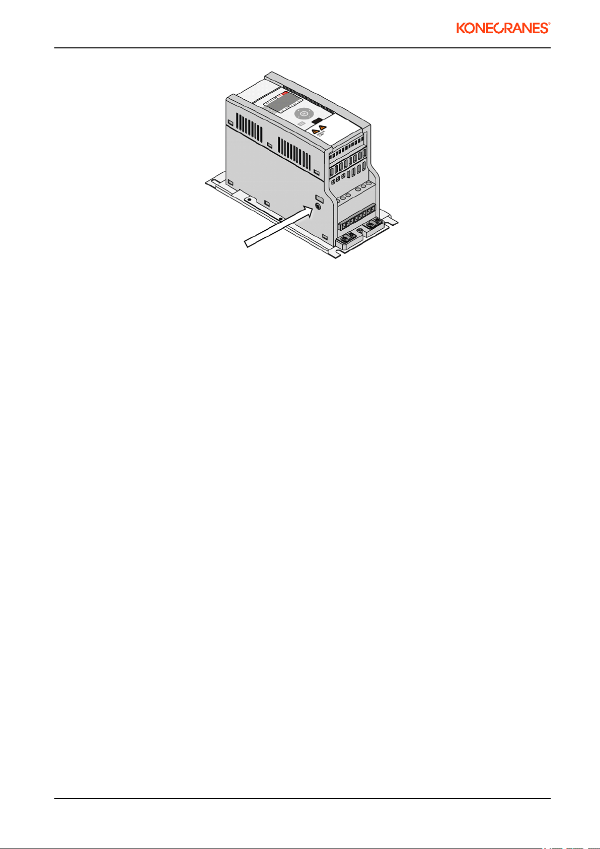
4.5 New frequency controller installation............................................................................................. 12
5 COMMISSIONING................................................................................................................................. 19
5.1 Old inverter parameter settings..................................................................................................... 19
5.2 Motor type..................................................................................................................................... 19
5.3 Traveling motor rating plate values............................................................................................... 19
5.4 Setting up the new inverter parameters......................................................................................... 19
6 TROUBLESHOOTING........................................................................................................................... 26
6.1 Purpose of troubleshooting........................................................................................................... 26
6.2 Problems and solutions................................................................................................................. 26
6.3 Fault codes and alarms................................................................................................................. 26
020145en / Revision D / 2015-04-29
2/31
This document and the information contained herein, is the exclusive property of Konecranes Plc. and represents a non-public, confidential and proprietary trade secret that may not be
reproduced, disclosed to other parties, altered or otherwise employed in any manner whatsoever without the express written consent of Konecranes Plc.
Copyright © (2014) Konecranes Plc. All rights reserved.

1 INTRODUCTION
1.1 About this manual
This manual offers guidance to the installation and start-up tasks of DynADrive 022 frequency converter
replacement.
As a maintenance technician, taking the time to read this manual will help you easily adopt the replacement
procedures. This manual is not intended as a substitute for proper training.
Please read through these instructions and make yourself familiar with all the steps before
proceeding.
More information can be found in the original Service Manuals of the specific device.
1.2 About the upgrade kit usage
This upgrade kit is designed only for DynADrive 022 frequency converter.
1.3 Waste treatment and recycling of removed material
The removed parts and packaging material shall be recycled according to local regulations. We recommend
recycling the frequency converter’s aluminum heat sink separately.
020145en / Revision D / 2015-04-29
3/31
This document and the information contained herein, is the exclusive property of Konecranes Plc. and represents a non-public, confidential and proprietary trade secret that may not be
reproduced, disclosed to other parties, altered or otherwise employed in any manner whatsoever without the express written consent of Konecranes Plc.
Copyright © (2014) Konecranes Plc. All rights reserved.

2 SAFETY
2.1 Before starting to work at the site
Before starting any work on the crane:
• Familiarize yourself with the equipment and its user instructions.
• Find out the location of the main switch and the emergency stop buttons.
• Evaluate the risks of the site and try to minimize them.
• Inform the site responsible that you will be working on the crane.
• Restrict access to the working area, if possible.
• Prevent unintentional use of the crane.
• Ensure that you have all the appropriate personal protection equipment. Use them as required.
2.2 Main switch and emergency stop buttons
Lock and tag the main switch when you need to switch it off during your work.
Electrical shock hazard
Touching live electrical circuit can cause serious injury.
Even though main switch is turned off, there may still be voltage inside electrical devices such as
inverters. Wait at least 5 minutes before opening covers.
2.3 After working at the site
Ensure that you leave the site in a safe condition:
• Ensure that the work area is clean.
• Remove any locks/tags from switches.
• Ensure that the crane functions normally.
• Inform the site responsible that you have finished the work.
020145en / Revision D / 2015-04-29
4/31
This document and the information contained herein, is the exclusive property of Konecranes Plc. and represents a non-public, confidential and proprietary trade secret that may not be
reproduced, disclosed to other parties, altered or otherwise employed in any manner whatsoever without the express written consent of Konecranes Plc.
Copyright © (2014) Konecranes Plc. All rights reserved.

3 DESCRIPTION OF THE UPGRADE KIT
3.1 Parts included in the kit
Part Name Qty. Image
Part 1 Frequency converter 1 pcs
Part 2 Mounting rack 1 pcs
Part 3 Installation accessory 1 pcs
Installation accessory
Part Name Qty. Image
Part 1 Cable tie 3 pcs
Part 2 Wire marker set 1 pcs
Part 3 Cleaning pad 1 pcs
Part 4 Wire end ferrule
2,5mm²
10 pcs
Part 5 M5 x 10 Flanged screw 10 pcs
020145en / Revision D / 2015-04-29
5/31
This document and the information contained herein, is the exclusive property of Konecranes Plc. and represents a non-public, confidential and proprietary trade secret that may not be
reproduced, disclosed to other parties, altered or otherwise employed in any manner whatsoever without the express written consent of Konecranes Plc.
Copyright © (2014) Konecranes Plc. All rights reserved.

3.2 Required tools
Item
No Name Image
1 Screwdriver, slot -head, 3,5 x 0,6mm
2 Wire strippers
3 Wire cutters
4 Crimping tool for wire end ferrules
5 Socket wrench, 8mm
020145en / Revision D / 2015-04-29
6/31
This document and the information contained herein, is the exclusive property of Konecranes Plc. and represents a non-public, confidential and proprietary trade secret that may not be
reproduced, disclosed to other parties, altered or otherwise employed in any manner whatsoever without the express written consent of Konecranes Plc.
Copyright © (2014) Konecranes Plc. All rights reserved.

3.3 Terminal connections
Table 1. Power terminals
Description of Terminal DynADrive 022
Terminal X2
DynA45 006 Power terminals
Power supply, phase 1 L1 L1
Power supply, phase 2 L2 L2/N
Power supply, phase 3 L3 L3
Motor supply, phase 1 U U/T1
Motor supply, phase 2 V V/T2
Motor supply, phase 3 W W/T3
Braking resistor, positive R+ R+
Braking resistor, negative R- R-
Protective earth PE PE
Table 2. Control terminals
DynADrive 022 DynA45 006
Description of Terminal Terminal
X1
Description Control board
terminals
Drive command, direction 1 1 Drive command, direction 1 1
Drive command, direction 2 2 Drive command, direction 2 2
Speed 2 / Acceleration command 3 Speed 2 / Acceleration
command
3
Slowdown/Stop limit, direction 1 4 Common slowdown,
Slowdown/Stop limit, direction
1
4
Slowdown/Stop limit, direction 2 5 Common stop, Slowdown/
Stop limit, direction 2
5
Common DI1-5 6 Motor temperature
protection / External stop
6
Normally open relay contact 7 Common DI1-6 7
Normally open relay contact 8 Normally open relay contact 8
Empty 9 Normally open relay contact 9
Motor thermistor, T1 10
Motor Thermistor, T2 11
Terminal X1 and control board terminal pins may have different functions!
020145en / Revision D / 2015-04-29
7/31
This document and the information contained herein, is the exclusive property of Konecranes Plc. and represents a non-public, confidential and proprietary trade secret that may not be
reproduced, disclosed to other parties, altered or otherwise employed in any manner whatsoever without the express written consent of Konecranes Plc.
Copyright © (2014) Konecranes Plc. All rights reserved.

3.4 User interface
DynADrive 022 has 6 groups of DIP switches (S1-S6), whereas DynA45 006 has operating digital panel and
large menu structure. The correct parameter settings for DynA45 006 can be found in chapter:
"Commissioning".
DynADrive 022 DynA45 006
Switch Description No: Description
S1 Maximum driving frequency 1. Drive status
S2 Minimum driving frequency 2. Control selection
S3 Acceleration and
deceleration ramp times
3. Main menu
S4 Control mode and motor
type
4. Back/reset button
S5 Motor current limit 5. Navigation and confirmation (OK) buttons.
S6 Limit operation settings
3.5 EMC filter
DynADrive 022 has an external EMC filter package (KC310 / KC330), whereas DynA45 has an internal EMC
filter in the power supply. By default, the EMC level of the frequency converter is set to N by the manufacturer.
If the mains network is non-grounded (IT-network), the DynA45 006 frequency converter’s EMC level must be
changed to 0 by removing the filter capacitor disconnection screw.
Verify the type of electrical supply network from original electrical drawings.
020145en / Revision D / 2015-04-29
8/31
This document and the information contained herein, is the exclusive property of Konecranes Plc. and represents a non-public, confidential and proprietary trade secret that may not be
reproduced, disclosed to other parties, altered or otherwise employed in any manner whatsoever without the express written consent of Konecranes Plc.
Copyright © (2014) Konecranes Plc. All rights reserved.

020145en / Revision D / 2015-04-29
9/31
This document and the information contained herein, is the exclusive property of Konecranes Plc. and represents a non-public, confidential and proprietary trade secret that may not be
reproduced, disclosed to other parties, altered or otherwise employed in any manner whatsoever without the express written consent of Konecranes Plc.
Copyright © (2014) Konecranes Plc. All rights reserved.

4 INSTALLATION
4.1 Preparations
Before you start, be sure to take into account the following matters:
• If the crane is drivable, check the trolley/bridge driving directions before switching the main power off.
• Check that the main power switch is off (lock and tag procedure).
• Always follow all local safety regulations and instructions.
WARNING High voltage inside the device.
Wait for at least five minutes after the voltage supply has been switched of
before taking any service actions.
4.2 Old frequency converter removal
1If the trolley is operable (not broken), record the trolley driving directions.
2Push the main power off from the pendant or radio controller.
WARNING High voltage inside the Frequency converter.
Wait for at least five minutes after the voltage supply has been
switched of before taking any service actions.
3DynA45 006 has an internal EMC filter. The old EMC filter can be removed. Cut the ground wire and
the power supply wires (L1, L2, L3) right next to the connector and mark them with the yellow wire
marks (Part 17). The old EMC filter can remain on the DynADrive 022 body.
020145en / Revision D / 2015-04-29
10/31
This document and the information contained herein, is the exclusive property of Konecranes Plc. and represents a non-public, confidential and proprietary trade secret that may not be
reproduced, disclosed to other parties, altered or otherwise employed in any manner whatsoever without the express written consent of Konecranes Plc.
Copyright © (2014) Konecranes Plc. All rights reserved.

4Disconnect and mark the motor supply wires (U, V and W) with cable markers. If the DynADrive 022
has an external braking resistor, disconnect the braking resistor wires and remove the braking resistor.
Disconnect the control wires and mark them according to the next table.
Pin in
DynADrive 022
Connect to pin number in DynA45 006 Function
1 1 Drive command, direction 1
2 2 Drive command, direction 2
3 3 Speed 2 / Acceleration command
4 4 Slowdown/stop limit, direction 1
5 5 Slowdown/stop limit, direction 2
6 7 Common for Digital Inputs
7* 8 Normally open relay contact
8* 9 Normally open relay contact
10** Connect to OL10 signal Supply voltage for motor bi-metal
thermal protection
11** 6 Motor thermal protection
*) If there are no wires connected in pins 7 and 8 in DynADrive 022 , the relay is not in use and thus
must not be marked.
**)If the pins 10 and 11 are connected together, the motor thermal protection is not in use and thus
pin number 6 must be connected to OL10 signal. If there are two motors, there are two thermal
protection circuits which must be connected in series.
If there is a thermistor installed in the motor, a thermistor relay ,e.g. MSL, must be installed to
thermal protection circuit of the motor. Pin number 6 must be connected to OL10 via MSL.
5Loosen and remove the screws (4 pcs) holding the DynADrive 022 . Remove the DynADrive 022 and
the EMC-filter from the enclosure. Note: The old screws are self-tapping so they must not be re-used.
Use the delivered screws (part 8) instead.
6Strip all the wires up to 10 mm. If the wires have thin strands, use wire end ferrules (Part 21) as shown
in the picture.
4.3 Control voltage front resistors
The control voltage range in the DynADrive 022 was 48V - 115V. If the control voltage was 230V, the front
resistors were used to decrease the control voltage to 115V or 48V. In the DynA45 006 the control voltage
range is 42V - 230V. Therefore you must remove or by-pass the possible front resistors when upgrading the
DynADrive 022 to DynA45 006 .
If the front resistors are not removed or by-passed, the control inputs on the DynA45 006
frequency converter are not activated, even though voltage can be measured with a
multimeter.
4.4 By-passing the control voltage front resistor
020145en / Revision D / 2015-04-29
11/31
This document and the information contained herein, is the exclusive property of Konecranes Plc. and represents a non-public, confidential and proprietary trade secret that may not be
reproduced, disclosed to other parties, altered or otherwise employed in any manner whatsoever without the express written consent of Konecranes Plc.
Copyright © (2014) Konecranes Plc. All rights reserved.

1Remove the control signal wires from the top side of
the front resistor.
2Connect the control signal wires to the bottom side of
the front resistor. See the picture below.
Do not mix the order of the wires.
4.5 New frequency controller installation
1If the DynADrive 022 has an external braking resistor: install the braking resistor to suitable place
close to DynA45 006 in the crane. Install the braking resistor wire from the braking resistor to the
cubicle.
2Put 4 pcs , size M5 x 10 Flanged installation screws
into back plate. Leave screws loose. The installation
rack has slotted screw holes.
020145en / Revision D / 2015-04-29
12/31
This document and the information contained herein, is the exclusive property of Konecranes Plc. and represents a non-public, confidential and proprietary trade secret that may not be
reproduced, disclosed to other parties, altered or otherwise employed in any manner whatsoever without the express written consent of Konecranes Plc.
Copyright © (2014) Konecranes Plc. All rights reserved.

3Put the installation rack (part 2) into place . Tighten the
screws.
4Put 4 pcs, size M5 x 10 Flanged installation screws
into assembly rack. Leave screws loose. The inverter
has slotted screw holes.
5Put the DynA45 006 into place. Tighten the screws.
6Connect the power supply and motor wires in DynA45 according to electrical drawings.
7Connect extra grounding wire from new inverter PE(protective earth) terminal to ground. Wire length
should not exceed 10 cm. The wire size should be minimum of 2.5 mm². This extra grounding wire is
not delivered with the package.
8If the DynADrive 022 has an external braking resistor: Remove the internal braking resistor wires and
connect the braking resistor cable to DynA45 006 according to the electrical drawings.
020145en / Revision D / 2015-04-29
13/31
This document and the information contained herein, is the exclusive property of Konecranes Plc. and represents a non-public, confidential and proprietary trade secret that may not be
reproduced, disclosed to other parties, altered or otherwise employed in any manner whatsoever without the express written consent of Konecranes Plc.
Copyright © (2014) Konecranes Plc. All rights reserved.

9Connect the control wires according to the next instructions. Look at the original electrical drawings to
see how the original application is built. There are five different variations how control wires can be
connected.
Variation 1 - MS2+stop . EP2 or MS2 control with stop limit.
Figure 1. Old inverter + MS2 + stop
Figure 2. New inverter + MS2 + stop
Digital input 5 in DynA45 will be deactivated. No connection is needed.
020145en / Revision D / 2015-04-29
14/31
This document and the information contained herein, is the exclusive property of Konecranes Plc. and represents a non-public, confidential and proprietary trade secret that may not be
reproduced, disclosed to other parties, altered or otherwise employed in any manner whatsoever without the express written consent of Konecranes Plc.
Copyright © (2014) Konecranes Plc. All rights reserved.

Variation 2 - EP2+slow down. MS2 control method with slowdown limit switch. With DynA45 both
direction signals from limit switch must be connected in series as shown in below figures.
Figure 3. Old inverter + EP2 + slow down
Figure 4. New inverter + EP2 + slow down
Digital input 5 in DynA45 will be deactivated. No connection is needed.
Variation 3 - EP2 / MS2 + stop.
020145en / Revision D / 2015-04-29
15/31
This document and the information contained herein, is the exclusive property of Konecranes Plc. and represents a non-public, confidential and proprietary trade secret that may not be
reproduced, disclosed to other parties, altered or otherwise employed in any manner whatsoever without the express written consent of Konecranes Plc.
Copyright © (2014) Konecranes Plc. All rights reserved.

Figure 5. Old inverter + EP2 / MS2 + stop
Figure 6. New inverter + EP2 / MS2 + stop
Digital inputs 4 and 5 in DynA45 will be deactivated. No connection is needed.
Variation 4 - MS2 + 2-step limit switch.
020145en / Revision D / 2015-04-29
16/31
This document and the information contained herein, is the exclusive property of Konecranes Plc. and represents a non-public, confidential and proprietary trade secret that may not be
reproduced, disclosed to other parties, altered or otherwise employed in any manner whatsoever without the express written consent of Konecranes Plc.
Copyright © (2014) Konecranes Plc. All rights reserved.

Figure 7. Old inverter + MS2 + 2-step limit switch
Figure 8. New inverter + MS2 + 2-step limit switch
Variation 5 - EP2 + 2-step limit switch. With DynA45 the both slowdown direction signals from limit
switch must be connected in series.
020145en / Revision D / 2015-04-29
17/31
This document and the information contained herein, is the exclusive property of Konecranes Plc. and represents a non-public, confidential and proprietary trade secret that may not be
reproduced, disclosed to other parties, altered or otherwise employed in any manner whatsoever without the express written consent of Konecranes Plc.
Copyright © (2014) Konecranes Plc. All rights reserved.

Figure 9. Old inverter + EP2 + 2-step limit switch
Figure 10. New inverter + MS2 + 2-step limit switch
020145en / Revision D / 2015-04-29
18/31
This document and the information contained herein, is the exclusive property of Konecranes Plc. and represents a non-public, confidential and proprietary trade secret that may not be
reproduced, disclosed to other parties, altered or otherwise employed in any manner whatsoever without the express written consent of Konecranes Plc.
Copyright © (2014) Konecranes Plc. All rights reserved.

5 COMMISSIONING
5.1 Old inverter parameter settings
Write down the old parameter settings from the DynADrive 022 frequency converter in the table below.
Table 1: DynADrive 022 parameter settings
Dip
switch
position
Switch 1 Switch 2 Switch 3 Switch 4 Switch 5 Switch 6
-1 -2 -3 -4 -1 -2 -3 -4 -1 -2 -3 -4 -1 -2 -3 -4 -1 -2 -3 -4 -1 -2 -3 -4
ON
OFF
5.2 Motor type
Record the motor type. You need to verify if you're motor is equipped with compact brake. This information is
later used on the commissioning steps. The commissioning steps are different with compact brake motors.
Motor type
Compact brake motor types
MF06MA200
MF06MA100
MF06LA200
MF06LA100
5.3 Traveling motor rating plate values
Record the traveling brake rating plate values for further use on commissioning.
Name Motor rating plate value
Motor Nom Volt [V]
Motor Nom Freq [Hz]
Motor Nom Speed [rpm]
Motor Nom Curr [A]
Nom Magnetizing Curr [A]
Motor Cos Phi
5.4 Setting up the new inverter parameters
Compare the DIP switch settings of the DynADrive 022 with the following tables and find correct settings for
the DynA45 006 parameter settings.
1At the DynA45 006 frequency converter; set parameter P1.1 to value 129. This sets the engineering
password level which is needed for parameter settings.
020145en / Revision D / 2015-04-29
19/31
This document and the information contained herein, is the exclusive property of Konecranes Plc. and represents a non-public, confidential and proprietary trade secret that may not be
reproduced, disclosed to other parties, altered or otherwise employed in any manner whatsoever without the express written consent of Konecranes Plc.
Copyright © (2014) Konecranes Plc. All rights reserved.

2Set the nominal driving frequency. Driving frequency depends on the chosen nominal frequency of the
motor. Use table 1 to determine which table must be used to set the maximum and minimum driving
frequencies. Note that switch S4-3 and S4-4 are not shown, because these were used for the IR-
compensation purpose in the DynADrive 022 inverter.
Table 3. Selecting Maximum and Minimum frequency table
DynADrive 022 Table Nominal Frequency
(Hz)
Switch S4
-1 -2
0 0 4 100/120
1 0 5 80
0 1 6 50/60
Table 4. Maximum and minimum frequency 100/120 Hz
DynADrive 022 Minimum frequency
(Hz) To P1.2
Maximum Frequency
(Hz) To P1.3
Switch S1
-1 -2 -3 -4
0 0 0 0 29 100
0 0 0 1 14 50
0 0 1 0 23 62
0 0 1 1 10 54
0 1 0 0 32 80
0 1 0 1 12 58
0 1 1 0 16 66
0 1 1 1 18 70
1 0 0 0 50 115
1 0 0 1 20 75
1 0 1 0 26 85
1 0 1 1 35 90
1 1 0 0 38 95
1 1 0 1 41 105
1 1 1 0 44 110
1 1 1 1 47 120
020145en / Revision D / 2015-04-29
20/31
This document and the information contained herein, is the exclusive property of Konecranes Plc. and represents a non-public, confidential and proprietary trade secret that may not be
reproduced, disclosed to other parties, altered or otherwise employed in any manner whatsoever without the express written consent of Konecranes Plc.
Copyright © (2014) Konecranes Plc. All rights reserved.
Table of contents