Kongsberg Seapath 320 User manual

Seapath®320
Technical Description

Seapath 320
II Man_techn_seapath320/rev.1
About this document
Rev Date Written by Checked by Approved by
Rev. 1 2010-03-22 FOS ISt FOS
First issue of this manual
Rev. 2
Copyright
© 2010 Kongsberg Seatex AS. All rights reserved. No part of this work covered by the
copyright hereon may be reproduced or otherwise copied without prior permission from
Kongsberg Seatex AS.
Disclaimer
The information contained in this document is subject to change without prior notice.
Kongsberg Seatex AS shall not be liable for errors contained herein or for incidental or
consequential damages in connection with the furnishing, performance, or use of this
document.

Technical Description
Man_techn_seapath320/rev.1 III
Table of contents
1PRODUCT DESCRIPTION ...................................................1
1.1Purpose and application ...........................................................................................1
1.2System components..................................................................................................2
1.2.1The Processing Unit.................................................................................................. 3
1.2.2The HMI Unit........................................................................................................... 4
1.2.3The MRU 5............................................................................................................... 5
1.2.4The GNSS antennas and antenna bracket................................................................. 6
1.3Networked architecture............................................................................................7
2TECHNICAL SPECIFICATIONS ...........................................9
2.1Performance data......................................................................................................9
2.2Physical dimensions.................................................................................................9
2.2.1Processing Unit
......................................................................................................... 9
2.2.2HMI Unit .................................................................................................................. 9
2.2.3Monitor, 17-inch LCD............................................................................................ 10
2.2.4MRU Unit............................................................................................................... 10
2.2.5MRU Wall Mounting Bracket ................................................................................ 10
2.2.6MRU Junction Box................................................................................................. 10
2.2.7Antenna Bracket ..................................................................................................... 11
2.2.8GNSS antenna
......................................................................................................... 11
2.2.9Cabinet.................................................................................................................... 11
2.3Power .....................................................................................................................11
2.3.1Processing Unit
....................................................................................................... 11
2.3.2HMI Unit ................................................................................................................ 12
2.3.3Monitor, 17-inch LCD............................................................................................ 12
2.3.4MRU....................................................................................................................... 12
2.3.5GNSS antenna
......................................................................................................... 12
2.4Environmental........................................................................................................12
2.4.1Processing Unit
....................................................................................................... 12
2.4.2HMI Unit ................................................................................................................ 13
2.4.3Monitor, 17-inch LCD............................................................................................ 13
2.4.4MRU Unit............................................................................................................... 13

Seapath 320
IV Man_techn_seapath320/rev.1
2.4.5GNSS antenna......................................................................................................... 13
2.5External interfaces..................................................................................................14
2.5.1Processing Unit
....................................................................................................... 14
2.5.2HMI Unit ................................................................................................................ 14
2.5.3MRU Unit............................................................................................................... 14
2.6Product safety.........................................................................................................14
2.6.1Processing Unit
....................................................................................................... 14
2.7Radio frequencies...................................................................................................15
2.7.1GNSS antenna
......................................................................................................... 15
2.7.2GNSS receiver........................................................................................................ 15
2.8Data outputs ...........................................................................................................15
2.8.1Processing Unit
....................................................................................................... 15
2.9Data inputs .............................................................................................................16
2.9.1Processing Unit
....................................................................................................... 16
2.10Compass safe distance ...........................................................................................16
2.10.1Processing Unit
....................................................................................................... 16
2.11Cables.....................................................................................................................16
2.11.1MRU cable
.............................................................................................................. 16
2.11.2Processing Unit to MRU Junction Box cable......................................................... 16
2.11.3GNSS antenna cables (Coax)
.................................................................................. 17
2.12Interfaces Processing Unit .....................................................................................18
2.12.1RS-422 A and B signal definition........................................................................... 19
2.12.2Pin layout................................................................................................................ 19
2.12.3MRU to Processing Unit cable wiring.................................................................... 25
2.13Interfaces HMI Unit...............................................................................................26
2.13.1Pin layout................................................................................................................ 27
3INSTALLATION................................................................29
3.1Logistics.................................................................................................................29
3.2Location of the system parts ..................................................................................29
3.2.1GNSS antennas....................................................................................................... 30
3.2.2MRU 5.................................................................................................................... 31
3.2.3Processing Unit
....................................................................................................... 32
3.2.4HMI Unit ................................................................................................................ 32

Technical Description
Man_techn_seapath320/rev.1 V
3.2.5Monitor................................................................................................................... 32
3.3Survey of sensors on vessels..................................................................................33
3.3.1Vessel reference system.......................................................................................... 33
3.3.2MRU....................................................................................................................... 33
3.3.3GNSS antennas....................................................................................................... 34
3.3.4Gyro........................................................................................................................ 34
3.3.5Survey accuracy...................................................................................................... 34
3.3.6Cabinet mounting ................................................................................................... 35
4CONFIGURATION ............................................................37
4.1Starting the system.................................................................................................37
4.2System configuration .............................................................................................37
4.2.1System modes......................................................................................................... 37
4.3NavEngine configuration.......................................................................................38
4.4Standard configuration...........................................................................................38
4.4.1Vessel configuration............................................................................................... 40
4.4.2GNSS configuration ............................................................................................... 41
4.4.3DGNSS configuration
............................................................................................. 45
4.4.4MRU configuration
................................................................................................. 45
4.4.5Monitoring points................................................................................................... 48
4.4.6Communication interface........................................................................................ 52
4.4.7Data pool
................................................................................................................. 53
5OPERATING INSTRUCTIONS ...........................................55
5.1Screen sections views.............................................................................................55
5.1.1Switch and select views.......................................................................................... 56
5.2Top bar...................................................................................................................56
5.3Sky view.................................................................................................................58
5.4DGNSS views ........................................................................................................60
5.5Integrity view.........................................................................................................62
5.6Compass view ........................................................................................................64
5.7Motion Data view...................................................................................................64
5.8Time Series view....................................................................................................65
5.9View menu.............................................................................................................66
5.9.1Display mode.......................................................................................................... 67

Seapath 320
VI Man_techn_seapath320/rev.1
5.10Tools menu.............................................................................................................68
5.10.1Utilities ................................................................................................................... 68
5.10.2Diagnostics ............................................................................................................. 68
5.10.3Log.......................................................................................................................... 69
5.11System menu..........................................................................................................69
5.11.1Configuration.......................................................................................................... 70
5.11.2Information............................................................................................................. 70
6DRAWINGS .....................................................................71
6.1Processing and HMI Units.....................................................................................72
6.2Antenna bracket .....................................................................................................74
6.3MRU and mounting bracket...................................................................................75
6.4MRU junction box .................................................................................................77
6.5GNSS antenna mechanical drawings.....................................................................78
6.6GNSS antenna installation .....................................................................................79
6.76 U cabinet dimensions..........................................................................................81
7PART LIST.......................................................................83
List of figures
Figure 1 Typical information shown to the user..............................................................2
Figure 2 System architecture...........................................................................................3
Figure 3 Front panel of Processing Unit..........................................................................4
Figure 4 Rear panel of Processing Unit...........................................................................4
Figure 5 Front panel of HMI Unit...................................................................................4
Figure 6 Rear panel of HMI Unit ....................................................................................5
Figure 7 The MRU 5 .......................................................................................................5
Figure 8 MRU 5 functional modules...............................................................................6
Figure 9 Antenna Bracket................................................................................................7
Figure 10 Side view of GNSS antenna installation.........................................................7
Figure 11 Rear panel of Processing Unit without chord anchorage..............................18
Figure 12 Connector board............................................................................................20
Figure 13 External alarm connection diagram ..............................................................22

Technical Description
Man_techn_seapath320/rev.1 VII
Figure 14 Location of system parts ...............................................................................30
Figure 15 Change system mode menu...........................................................................37
Figure 16 NavEngine configuration..............................................................................38
Figure 17 NavEngine Configuration view ....................................................................38
Figure 18 History button ...............................................................................................39
Figure 19 Configuration manager..................................................................................39
Figure 20 Vessel geometry view...................................................................................40
Figure 21 Vessel Description view................................................................................41
Figure 22 GNSS sensor geometry configuration view..................................................42
Figure 23 GNSS Processing settings view....................................................................43
Figure 24 GNSS Attitude Processing view ...................................................................44
Figure 25 SBAS tracking view......................................................................................45
Figure 26 MRU geometry view.....................................................................................46
Figure 27 Heave filter view...........................................................................................48
Figure 28 Monitoring points view.................................................................................49
Figure 29 Add a new monitoring point .........................................................................50
Figure 30 New monitoring point, MP4, added to list....................................................51
Figure 31 Renaming of monitoring point to preferred name.........................................51
Figure 32 Input/output view before interface details are added....................................52
Figure 33 Input/Output list view with configuration details ..........................................53
Figure 34 Data Pool configuration view .......................................................................53
Figure 35 Main view sections........................................................................................55
Figure 36 Top bar..........................................................................................................56
Figure 37 Sky view........................................................................................................59
Figure 38 Satellite colours.............................................................................................59
Figure 39 Satellites with two signal-to-noise bars.........................................................59
Figure 40 Tooltip for GPS satellite with corrections.....................................................60
Figure 41 Tooltip for GLONASS satellite with corrections .........................................60
Figure 42 DGNSS status view.......................................................................................61
Figure 43 DGNSS age view ..........................................................................................62
Figure 44 Integrity view................................................................................................63
Figure 45 Compass view...............................................................................................64
Figure 46 Motion Data view..........................................................................................65

Seapath 320
VIII Man_techn_seapath320/rev.1
Figure 47 Times Series view showing data for roll, pitch, heave and heading.............66
Figure 48 View menu....................................................................................................67
Figure 49 Dusk mode ....................................................................................................68
Figure 50 Day black mode ............................................................................................68
Figure 51 Tools menu....................................................................................................68
Figure 52 System menu.................................................................................................69
Figure 53 The NavEngine Configuration menu............................................................70
Figure 54 Quick Help dialog.........................................................................................70
List of tables
Table 1 GNSS antenna cable specification ...................................................................17
Table 2 Connectors at rear of Processing Unit..............................................................19
Table 3 Connectors at front of Processing Unit ............................................................19
Table 4 Pin layout of Com 1 and Com 2.......................................................................20
Table 5 Pin layout of Com 9 through Com 14 ..............................................................21
Table 6 Pin layout of PPS port ......................................................................................21
Table 7 Pin layout of Alarm..........................................................................................22
Table 8 Pin layout of Analog Out..................................................................................23
Table 9 Pin layout of MRU ...........................................................................................24
Table 10 Pin layout for LAN 1 Ethernet ports ..............................................................24
Table 11 Pin layout for LAN 2, 3 and 4 Ethernet ports.................................................25
Table 12 MRU to Processing Unit cable wiring............................................................26
Table 13 Connectors at rear of HMI Unit .....................................................................27
Table 14 Connectors at front of HMI Unit....................................................................27
Table 15 Pin layout for HMI Unit Ethernet ports..........................................................27

Technical Description
Man_techn_seapath320/rev.1 IX
Abbreviations
AP Aft Perpendicular. The vertical intersection of the design waterline
at the stern, alternatively the centreline of the rudder stock.
BL Base Line. Is the same as the keel for a vessel with horizontal keel
line.
C/A Coarse/Acquisition
CEP Circular Error Probability
CG Centre of gravity. The mass centre of a vessel. This is normally the
location with least linear acceleration, and hence the best location
for measurements of roll and pitch.
CL Centre Line. Is the longitudinal axis along the centre of the ship
DGLONASS Differential GLONASS
DGNSS Differential Global Navigation Satellite System
DGPS Differential GPS
ED50 European Datum of 1950
EGNOS European Geostationary Navigation Overlay System (SBAS-
Europe)
EPE Estimated Position Error
GLONASS Global Navigation Satellite System. A Russian system
GNSS Global Navigation Satellite System
GPS Global Positioning System. The American NAVSTAR system.
GPS Time The time in the GPS system. The GPS time is within UTC time
±180 nsec (95 per cent) plus leap second
GUI Graphical User Interface
HMI Human Machine Interface
HP High Precision
IALA International Association of Lighthouse Authorities
IMU Inertial Measurement Unit
LED Light Emitting Diode
LGND Logic Ground
LOA Length OverAll
MMSI Maritime Mobile Service Identity
MP Monitoring Point

Seapath 320
X Man_techn_seapath320/rev.1
MRU 5 Motion Reference Unit, model 5. This is the IMU within the
Seapath measuring dynamic linear motion and attitude. A MRU
consists of gyros and accelerometers.
MSAS Multifunctional transport Satellite-based Augmentation System
(SBAS-Japan)
NAD27 North American Datum of 1927
NMEA National Marine Electronics Association. NMEA 0183 is a standard
for interchange of information between navigation equipment.
NRP Navigation Reference Point. The reference point for all
measurements in Seapath. The recommended used NR is the vessel
CG or rotation centre.
PGND Power Ground
PPS Pulse Per Second
PRN Pseudorandom Noise
PSS Physical Shore Station
RAIM Receiver Autonomous Integrity Monitoring
RMS Root Mean Square
RTCM Radio Technical Commission of Maritime Services
SA Selective Availability
SBAS Satellite Based Augmentation System
SL Speed Along Ship
SNR Signal/Noise Ratio
SOG Speed Over Ground
SRRD Seatex Rescue and Restore Disk
ST Speed Transverse Ship
SW Software
UTC Universal Time Co-ordinated. This is the official time in the world
and has replaced GMT (Greenwich Mean Time) as the official time.
UTM Universal Transverse Mercator
WAAS Wide Area Augmentation System (SBAS-USA/Canada)
WEEE Waste Electrical and Electronic Equipment
WGS84 World Geodetic System of 1984

Technical Description
Man_techn_seapath320/rev.1 XI
Terminology
Alignment Is the process of adjusting the current internal navigation frame in
the instrument to the true external frame.
Antenna bracket Is the arrangement for mounting the GPS antennas.
Antenna holder Is the arrangement on board the vessel for mounting the antenna
bracket to.
Attitude The orientation relative to the vertical axis of a vehicle. Heading is
not included. If heading is included the word "orientation" is used
for the vehicle.
Beam The maximum width of the vessel at Main Deck level (B. mld).
GPS Time The time in the GPS system. The GPS time is within UTC time
±180 nsec (95 per cent) plus leap second.
Heading The direction of the main axis (bow direction) of the vehicle as
opposed to course, which is the direction of motion of the vehicle.
Yaw angle as defined here is the same as heading.
Heave The vertical dynamic motion of a vehicle and defined positive
down. Heave position and velocity are dynamic motion variables
oscillating around a mean value, typically zero.
Height The height in the Seapath product is defined as the vertical position
relative to the WGS84 datum (rotational ellipsoid).
Host system In this manual defined as Navigation computers, Dynamic
Positioning Systems, etc., receiving data from Seapath.
Origin The zero point in the coordinate system. The origin is the
intersection point between AP, BL and CL.
P-axis This axis is fixed in the vehicle, and points in the starboard
direction horizontally when the roll angle is zero. Positive rotation
about this axis is bow of the vehicle up.
Pitch A rotation about the pitch axis is positive when the bow moves up.
Normally, pitch means the dynamic pitch angle motions.
R-axis This axis is fixed in the vehicle, and points in the forward direction
horizontally when the pitch angle is zero. Positive rotation about
this axis is starboard side of the vehicle down.
Roll A rotation about the roll axis is positive when starboard side of the
vehicle moves down. Normally, roll means the dynamic roll angle
motion.
Starboard When looking in the bow direction of a vehicle, this is the right
hand side of the vehicle.

Seapath 320
XII Man_techn_seapath320/rev.1
Surge
The along ship dynamic motion of a vehicle and defined positive
forward.
Sway The athwart ship dynamic motion of a vehicle and defined positive
starboard.
Y-axis This axis is fixed in the vehicle and points in the downward
direction when the vehicle is aligned horizontally. Positive rotation
about this axis is turning the bow of the vehicle to starboard.
Yaw A rotation about the vertical axis is positive when turning Eastward
(Clockwise) when the vehicle cruises in North direction. Normally,
yaw means the dynamic yaw motion.
References
[1] M300-62, Seapath 320 Installation Manual
[2] NMEA 0183 Standard for Interfacing Marine Electronic Devices, Version
3.00
[3] RTCM Recommended Standards for Differential Navstar GPS Services,
Version 2.3

Technical Description
Man_techn_seapath320/rev.1 XIII
Health, environment and safety warnings
All electrical and electronic components have to be disposed
of separately from the municipal waste stream via designated
collection facilities appointed by the government or local
authorities. The correct disposal and separate collection of
your old appliance will help prevent potential negative
consequences for the environment and human health. It is a
precondition for reuse and recycling of used electrical and
electronic equipment. For more detailed information about
disposal of your old appliance, please contact your local
authorities or waste disposal service.
Until further notice is given regarding reuse, disassembly or
disposal, the equipment at end-of-life, could be returned to
Kongsberg Seatex AS if there is no local WEEE collection.
The equipment is marked with this pictogram.
Restrictions in export
Export of the MRU 5 component within the Seapath product to other countries than EU
countries or Argentina, Australia, Canada, Iceland, Japan, New Zealand, Switzerland,
South-Korea, Turkey, Ukraine and USA, requires an export license.
Notice to Importer: The MRU product specified in this document has been shipped from
Norway in accordance with The Ministry of Foreign Affairs' Official Notification on
Export Control and may be subject to restrictions if re-exported from your country.
Restrictions in guarantee
The liability of Kongsberg Seatex is limited to repair of the Seapath system only under
the given terms and conditions stated in the sales documents. Consequential damages
such as customer's loss of profit or damage to other systems traceable back to Seapath
malfunctions are excluded. The warranty does not cover malfunctions of the Seapath
resulting from the following conditions:
1 The MRU is not shipped in the original transport box.
2 The MRU has been exposed to extreme shock and vibrations.
3 The MRU housing has been opened by the customer in an attempt to carry out
repair work.
4 Over-voltage or incorrect power connection.
5 Shorting of GNSS antenna cable during operation of the Seapath systems.

Seapath 320
XIV Man_techn_seapath320/rev.1
Restrictions in use
The Seapath function is based on GNSS signals and requires free sight to the sky,
minimum four visible satellites, PDOP value less than 6 and otherwise normal
conditions to operate. It is designed for use on board marine surface operated vehicles
with linear acceleration less than ±30 m/s2(±3g) and an angular rate range less than
±150°/s.
Only relative dynamic heave position is calculated.

Technical Description
Man_techn_seapath320/rev.1 1
1PRODUCT DESCRIPTION
The Seapath 320 is a positioning, attitude and heading sensor. The product combines
inertial technology together with GPS and GLONASS satellite signals. Core
components in the product are the MRU 5 inertial sensor, the two combined
GPS/GLONASS receivers, the Processing and HMI Unit.
1.1 Purpose and application
The product is developed specifically for hydrographic and other high precision
applications where heading, position, roll, pitch, heave and timing are critical
measurements.
The Seapath 320 offers the best possible combination of GNSS signals and inertial
measurements for demanding operations in challenging environments. The possibility to
use GLONASS in addition to the GPS satellites significantly increases satellite
availability, provides robust integrity monitoring and results in more precise solutions,
particularly in highly obstructed environments.
The combination of GNSS signals and inertial data enables much better performance
than each of the signals alone, with a high output data rate (up to 200 Hz), zero delay on
output data, data available in up to eight different monitoring points and a total of eight
configurable serial lines and Ethernet ports.
This Seapath product is a two-module solution with a Processing and an HMI Unit
connected via Ethernet. The Processing Unit runs all critical computations independent
of the user interface on the HMI Unit to ensure continuous and reliable operation.
Several HMI Units can be connected to the same Processing Unit in a networked
architecture. The HMI Units present the vessel motion in a simple and easy-to-
understand format to ensure that the decision making based on the available data is as
efficient as possible.
Seapath 320
2 Man_techn_seapath320/rev.1
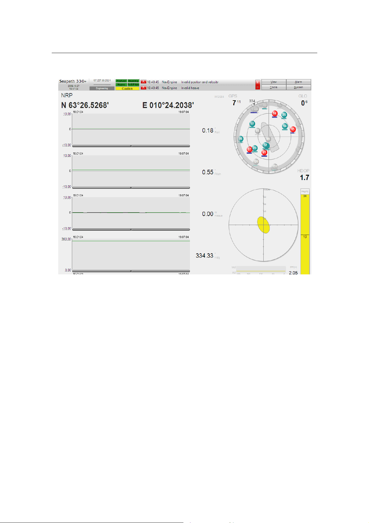
Figure 1 Typical information shown to the user
1.2 System components
The Seapath 320 comprises the following main components, which are physically
separated:
•A Processing Unit for I/O and calculations.
•An HMI Unit with MONITOR, keyboard and PC mouse.
•An MRU 5 inertial sensor.
•An MRU wall mounting bracket.
•An MRU junction box with three metres of cable for interfacing to the MRU.
•An Antenna Bracket with two GNSS antennas.
Technical Description
Man_techn_seapath320/rev.1 3
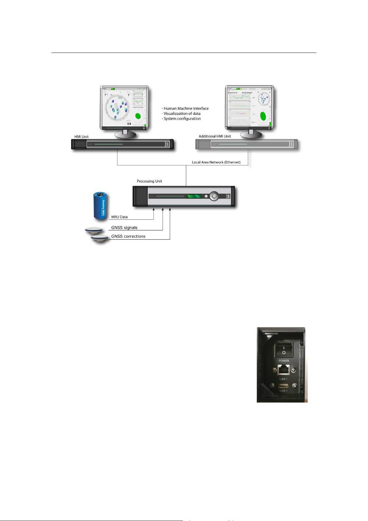
Figure 2 System architecture
1.2.1 The Processing Unit
The Processing Unit is designed to fit standard 19-inch racks and is typically installed
on the bridge or in the instrument room. The Processing Unit comprises the following
main parts:
•Hard disk
•Serial I/O board, Ethernet and computer main board
•Power supply
•Two GNSS receivers
The power on/off switch, LAN port and USB connection are
located under the lid on the left part of the front panel.

Seapath 320
4 Man_techn_seapath320/rev.1
Figure 3 Front panel of Processing Unit
The rear panel of the Processing Unit contains communication interface ports for
interfacing to external sensors. These ports are individually galvanically isolated.
Figure 4 Rear panel of Processing Unit
1.2.2 The HMI Unit
The HMI Unit is designed to fit 19-inch racks and is typically installed on the bridge or
in the instrument room. The 1U-height HMI Unit comprises the following main parts:
•Flash disk
•Serial I/O board, Ethernet and computer main board
•Power supply
The power on/off switch and USB connection are located
under the lid on the left part of the front panel.
Figure 5 Front panel of HMI Unit

Technical Description
Man_techn_seapath320/rev.1 5
Figure 6 Rear panel of HMI Unit
1.2.3 The MRU 5
The Seatex MRU 5 is specifically
designed for motion measurements in
marine applications. The unit incorporates
3-axis sensors for linear acceleration and
angular rate, along with complete signal
processing electronics and power supply.
The MRU 5 outputs absolute roll and
pitch. Dynamic acceleration in the MRU
axes direction as well as velocity and
relative position, are also provided. The
MRU achieves high reliability by using
sensors with no rotational or mechanical
wear out parts.
Figure 7 The MRU 5
When the MRU is used within the Seapath product, only raw angular rate and linear
acceleration data is output from the unit. All processing of these signals to roll, pitch,
heave and velocity measurements is performed in the Kalman filter in the Processing
Unit. The analog output channels from the MRU, as indicated in Figure 8, are therefore
not used when the MRU is used within the Seapath product.

Seapath 320
6 Man_techn_seapath320/rev.1
Figure 8 MRU 5 functional modules
The interior of the MRU is divided into two sub-assemblies consisting of an electronic
unit and a sensor unit. The electronic unit consists of plug-in circular multi-layer boards.
Extensive use is made of surface mounted components. The unit is divided into nine
separate mechanical parts, which may be exchanged very quickly by plug in boards
when the housing cylinder has been removed. The housing cylinder should, however,
not be removed by anyone else than Kongsberg Seatex.
The MRU is integrated in Seapath, and all digital data are routed through the Processing
Unit.
1.2.4 The GNSS antennas and antenna bracket
In a standard Seapath delivery, the Antenna Bracket is 2.5 metres. The Antenna Bracket
is delivered in aluminium. However, maximum heading accuracy is achieved with 4-
metre antenna separation. For antenna separations greater than 2.5 metres it is
recommended to mount each antenna separately on a rigid structure.
Other manuals for Seapath 320
1
Table of contents
Other Kongsberg Marine GPS System manuals

Popular Marine GPS System manuals by other brands

Garmin
Garmin Echomap Plus 40 series owner's manual

Garmin
Garmin GPSMAP 5008 - Marine GPS Receiver Quick reference guide

Garmin
Garmin GNX 20 installation instructions

SperryMarine
SperryMarine navigat x mk 1 Operation, installation and service manual

Garmin
Garmin GPSMAP 740 Quick reference guide

Beam
Beam Oceana 800 user manual


