Kongsberg Seapath 320 User manual

Seapath®320
Installation Manual

Seapath 320
II M300-62/rev.2
About this document
Rev
Date
Written by
Checked by
Approved by
Rev. 1
2010-02-24
FOS
FOS
First issue of this manual
Rev. 2
2010-06-25
FOS
FOS
Description of serial port extender and minor changes in the text
Copyright
© 2010 Kongsberg Seatex AS. All rights reserved. No part of this work covered by the
copyright hereon may be reproduced or otherwise copied without prior permission from
Kongsberg Seatex AS.
Disclaimer
The information contained in this document is subject to change without prior notice.
Kongsberg Seatex AS shall not be liable for errors contained herein or for incidental or
consequential damages in connection with the furnishing, performance, or use of this
document.

Installation Manual
M300-62/rev.2 III
Table of contents
1PRODUCT DESCRIPTION ...................................................1
1.1 Purpose and application ...........................................................................................1
1.2 System components..................................................................................................1
2TECHNICAL SPECIFICATIONS ...........................................5
2.1 Performance data......................................................................................................5
2.2 Physical dimensions.................................................................................................5
2.2.1 Processing Unit......................................................................................................... 5
2.2.2 HMI Unit .................................................................................................................. 5
2.2.3 Monitor, 17-inch LCD.............................................................................................. 6
2.2.4 MRU Unit................................................................................................................. 6
2.2.5 MRU Wall Mounting Bracket.................................................................................. 6
2.2.6 MRU Junction Box................................................................................................... 6
2.2.7 Antenna Bracket ....................................................................................................... 7
2.2.8 GNSS antenna........................................................................................................... 7
2.2.9 Cabinet...................................................................................................................... 7
2.3 Power .......................................................................................................................7
2.3.1 Processing Unit......................................................................................................... 7
2.3.2 HMI Unit .................................................................................................................. 8
2.3.3 Monitor, 17-inch LCD.............................................................................................. 8
2.3.4 MRU......................................................................................................................... 8
2.3.5 GNSS antenna........................................................................................................... 8
2.4 Environmental..........................................................................................................8
2.4.1 Processing Unit......................................................................................................... 8
2.4.2 HMI Unit .................................................................................................................. 9
2.4.3 Monitor, 17-inch LCD.............................................................................................. 9
2.4.4 MRU Unit................................................................................................................. 9
2.4.5 GNSS antenna........................................................................................................... 9
2.5 External interfaces..................................................................................................10
2.5.1 Processing Unit....................................................................................................... 10
2.5.2 HMI Unit ................................................................................................................ 10
2.5.3 MRU Unit............................................................................................................... 10

Seapath 320
IV M300-62/rev.2
2.6 Product safety.........................................................................................................10
2.6.1 Processing Unit....................................................................................................... 10
2.7 Radio frequencies...................................................................................................11
2.7.1 GNSS antenna......................................................................................................... 11
2.7.2 GNSS receiver........................................................................................................ 11
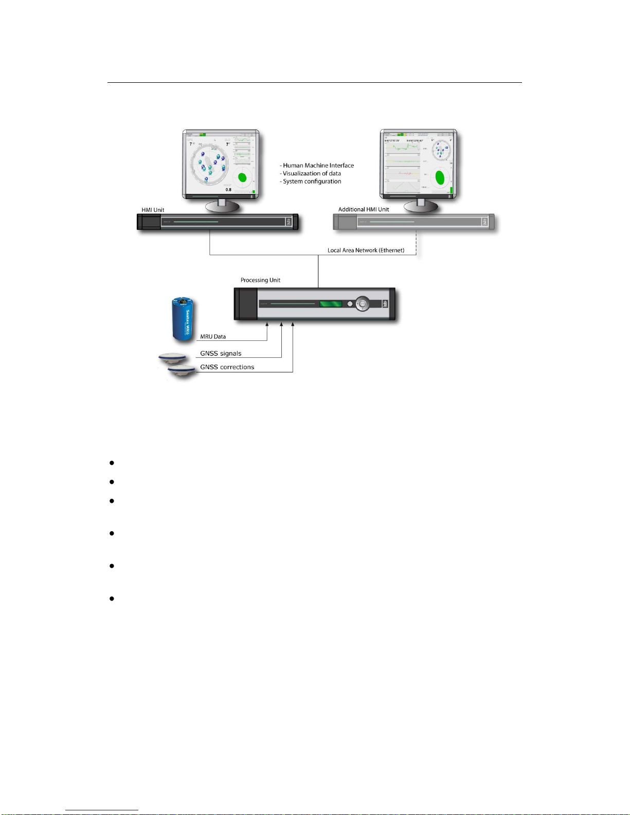
2.8 Data outputs ...........................................................................................................11
2.8.1 Processing Unit....................................................................................................... 11
2.9 Data inputs .............................................................................................................12
2.9.1 Processing Unit....................................................................................................... 12
2.10 Compass safe distance ...........................................................................................12
2.10.1Processing Unit....................................................................................................... 12
2.11 Cables.....................................................................................................................12
2.11.1MRU cable.............................................................................................................. 12
2.11.2Processing Unit to MRU Junction Box cable......................................................... 12
2.11.3GNSS antenna cables (Coax).................................................................................. 13
2.12 Interfaces Processing Unit .....................................................................................14
2.12.1RS-422 A and B signal definition........................................................................... 15
2.12.2Pin layout................................................................................................................ 15
2.12.3LED indicators Processing Unit ............................................................................. 21
2.12.4MRU to Processing Unit cable wiring.................................................................... 22
2.13 Interfaces HMI Unit...............................................................................................23
2.13.1Pin layout................................................................................................................ 24
2.13.2LED indicators HMI Unit....................................................................................... 25
3INSTALLATION................................................................27
3.1 Logistics.................................................................................................................27
3.2 Location of the system parts ..................................................................................27
3.2.1 GNSS antennas....................................................................................................... 28
3.2.2 MRU 5.................................................................................................................... 29
3.2.3 Processing Unit....................................................................................................... 30
3.2.4 HMI Unit ................................................................................................................ 30
3.2.5 Monitor................................................................................................................... 30
3.3 Survey of sensors on vessels..................................................................................31
3.3.1 Vessel reference system.......................................................................................... 31

Installation Manual
M300-62/rev.2 V
3.3.2 MRU....................................................................................................................... 31
3.3.3 GNSS antennas....................................................................................................... 32
3.3.4 Gyro........................................................................................................................ 32
3.3.5 Survey accuracy...................................................................................................... 32
3.3.6 Cabinet mounting ................................................................................................... 33
3.4 Installation procedures...........................................................................................33
3.4.1 Mechanical installation........................................................................................... 33
3.4.2 Electrical installation .............................................................................................. 39
3.4.3 Setup of configuration parameters.......................................................................... 42
3.4.4 Calibration .............................................................................................................. 43
4CONFIGURATION ............................................................51
4.1 Starting the system.................................................................................................51
4.2 System configuration .............................................................................................51
4.2.1 System modes......................................................................................................... 51
4.3 NavEngine configuration.......................................................................................52
4.4 Standard configuration...........................................................................................52
4.4.1 Vessel configuration............................................................................................... 54
4.4.2 GNSS configuration ............................................................................................... 58
4.4.3 DGNSS configuration............................................................................................. 61
4.4.4 MRU configuration................................................................................................. 61
4.4.5 Monitoring points ................................................................................................... 66
4.4.6 Communication interface........................................................................................ 70
4.4.7 Data pool................................................................................................................. 79

Seapath 320
VI M300-62/rev.2
4.5 Configuration backup.............................................................................................79
4.6 SRRD update..........................................................................................................80
5DRAWINGS .....................................................................83
5.1 Processing and HMI Units.....................................................................................84
5.2 Antenna bracket .....................................................................................................86
5.3 MRU and mounting bracket...................................................................................87
5.4 MRU junction box .................................................................................................89
5.5 GNSS antenna mechanical drawings.....................................................................90
5.6 6 U cabinet dimensions..........................................................................................91
APPENDIX A OUTPUT PROTOCOLS .......................................93
A.1 NMEA format ........................................................................................................93
A.2 Binary format 3......................................................................................................96
A.3 Simrad EM3000 format 6 ......................................................................................97
A.4 Calibration format..................................................................................................98
A.5 Echo sounder format 9...........................................................................................99
A.6 RDI ADCP format 10 ..........................................................................................100
A.7 Binary format 11..................................................................................................100
A.8 Lehmkuhl gyro repeater format 12 ......................................................................102
A.9 1PPS time tag, NMEA ZDA message .................................................................102
A.10 1PPS time tag, Trimble compatible .....................................................................103
A.11 Atlas Fansweep format 16....................................................................................103
A.12 Echo sounder format 18, TSS1 ............................................................................104
A.13 Binary format 23..................................................................................................105
A.14 PFreeHeave format 24 .........................................................................................106
A.15 Cyclic redundancy check algorithm.....................................................................107
APPENDIX B INSTALLATION OF COAX CONNECTORS ON
SUPERFLEX CABLE ...............................................................109
APPENDIX C GNSS ANTENNA INSTALLATION.....................115
APPENDIX D ½" COAX CABLE SPECIFICATION ..................117
APPENDIX E RG-214 SPECIFICATIONS ..............................119
APPENDIX F SERIAL PORT EXTENDER................................121
F.1 Mechanical installation ........................................................................................121

Installation Manual
M300-62/rev.2 VII
F.2 Electrical installation............................................................................................122
F.3 Configuration .......................................................................................................122
APPENDIX G FREE AND OPEN SOURCE SOFTWARE.............123
G.1 GNU General Public License...............................................................................123
G.2 GNU Lesser General Public License ...................................................................126
G.3 BSD License ........................................................................................................129
G.4 NTP License.........................................................................................................129
G.5 Berkeley DB License ...........................................................................................130
G.6 OpenSSL License.................................................................................................130
G.7 WU-FTPD Software License...............................................................................132
G.8 Ubuntu licensing ..................................................................................................132

Seapath 320
VIII M300-62/rev.2
List of figures
Figure 1 Standard system for 19-inch rack mounting .......................................................2
Figure 2 Rear panel of Processing Unit without chord anchorage.................................. 14
Figure 3 Connector board................................................................................................16
Figure 4 External alarm connection diagram .................................................................. 18
Figure 5 Front panel of Processing Unit..........................................................................21
Figure 6 Front view of HMI Unit....................................................................................25
Figure 7 Location of system parts ...................................................................................28
Figure 8 Dimensional drawing for antenna holder.......................................................... 34
Figure 9 Top view of Antenna Bracket........................................................................... 35
Figure 10 Different components for mounting of Antenna Bracket ............................... 35
Figure 11 Side view of GNSS antenna installation.........................................................36
Figure 12 Recommended orientation of the MRU mounting bracket.............................37
Figure 13 Wall mounting of bracket with MRU connector pointing down ....................37
Figure 14 Sticker (4) shall indicate actual MRU mounting orientation within bracket.. 38
Figure 15 MRU junction box mounting..........................................................................39
Figure 16 Offset vectors between the different components........................................... 43
Figure 17 Page 1 of GNSS antenna calibration............................................................... 46
Figure 18 Page 2 of antenna calibration wizard.............................................................. 47
Figure 19 Page 3 of antenna calibration wizard.............................................................. 47
Figure 20 Page 4 of antenna calibration wizard.............................................................. 48
Figure 21 Alignment of MRU yaw axis to vessel longitudinal axis ............................... 49
Figure 22 Value of roll error as a function of vessel pitch angle, displayed at 0.5°, 1°
and 1.5° MRU yaw misalignment.....................................................................................50
Figure 23 Change system mode menu.............................................................................51
Figure 24 NavEngine configuration................................................................................ 52
Figure 25 NavEngine Configuration view ......................................................................52
Figure 26 History button .................................................................................................53
Figure 27 Configuration manager....................................................................................53
Figure 28 Vessel geometry view..................................................................................... 54
Figure 29 Example GA drawing of multi-purpose vessel...............................................56
Figure 30 Example of vessel shape in user text file........................................................ 56
Figure 31 Example vessel shown in Vessel Geometry view........................................... 57

Installation Manual
M300-62/rev.2 IX
Figure 32 Vessel Description view..................................................................................57
Figure 33 GNSS sensor geometry configuration view.................................................... 59
Figure 34 GNSS Processing settings view...................................................................... 60
Figure 35 GNSS Attitude Processing view .....................................................................60
Figure 36 SBAS tracking view........................................................................................ 61
Figure 37 MRU geometry view....................................................................................... 62
Figure 38 Step 1 of MRU axis orientation ...................................................................... 63
Figure 39 Step 2 of Manual input of mounting angles....................................................63
Figure 40 Step 3 of Manual input of MRU mounting angles.......................................... 64
Figure 41 Heave filter view.............................................................................................66
Figure 42 Monitoring points view...................................................................................67
Figure 43 Add a new monitoring point ........................................................................... 68
Figure 44 New monitoring point, MP4, added to list...................................................... 69
Figure 45 Renaming of monitoring point to preferred name...........................................69
Figure 46 Input/output view before interface details are added...................................... 70
Figure 47 Input/Output list view with configuration details ............................................71
Figure 48 Configuration details view..............................................................................71
Figure 49 I/O properties view when serial interface is selected......................................72
Figure 50 I/O properties view when net interface is selected..........................................73
Figure 51 Interface set to TelegramOut...........................................................................73
Figure 52 Telegram output options ................................................................................. 74
Figure 53 Available NMEA telegrams............................................................................ 75
Figure 54 Gyro properties ...............................................................................................76
Figure 55 Telegram timing view..................................................................................... 76
Figure 56 DGNSS link properties ................................................................................... 77
Figure 57 Analog output properties................................................................................. 78
Figure 58 Data Pool configuration view .........................................................................79
Figure 59 Configuration Copier ...................................................................................... 80
Figure 60 Serial port extender with 8-ports................................................................... 121

Seapath 320
X M300-62/rev.2
List of tables
Table 1 GNSS antenna cable specification .....................................................................13
Table 2 Connectors at rear of Processing Unit................................................................ 15
Table 3 Connectors at front of Processing Unit .............................................................. 15
Table 4 Pin layout of Com 1 and Com 2.........................................................................16
Table 5 Pin layout of Com 9 through Com 14 ................................................................ 17
Table 6 Pin layout of PPS port ........................................................................................17
Table 7 Pin layout of Alarm............................................................................................ 18
Table 8 Pin layout of Analog Out....................................................................................19
Table 9 Pin layout of MRU .............................................................................................20
Table 10 Pin layout for LAN 1 Ethernet ports ................................................................20
Table 11 Pin layout for LAN 2, 3 and 4 Ethernet ports...................................................21
Table 12 MRU to Processing Unit cable wiring..............................................................23
Table 13 Connectors at rear of HMI Unit ....................................................................... 24
Table 14 Connectors at front of HMI Unit......................................................................24
Table 15 Pin layout for HMI Unit Ethernet ports............................................................24

Installation Manual
M300-62/rev.2 XI
Abbreviations
AP
Aft Perpendicular. The vertical intersection of the design
waterline at the stern, alternatively the centerline of the rudder
stock.
BL
Base Line. Is the same as the keel for a vessel with horizontal
keel line.
CEP
Circular Error Probability
CG
Centre of gravity. The mass centre of a vessel. This is normally
the location with least linear acceleration, and hence the best
location for measurements of roll and pitch.
CL
Centre Line. Is the longitudinal axis along the center of the
ship.
DGLONASS
Differential GLONASS
DGNSS
Differential Global Navigation Satellite System
DGPS
Differential GPS
ED50
European Datum of 1950
EGNOS
European Geostationary Navigation Overlay System (SBAS-
Europa)
EPE
Estimated Position Error
GLONASS
Global Navigation Satellite System
GNSS
Global Navigation Satellite System
GPS
Global Positioning System
GPS Time
The time in the GPS system. The GPS time is within UTC time
±180 nsec (95 per cent) plus leap second.
GUI
Graphical User Interface
HMI
Human Machine Interface
HP
High Precision
IALA
International Association of Lighthouse Authorities
IMO
International Maritime Organization
IMU
Inertial Measurement Unit
LGND
Logic Ground
MP
Monitoring Point

Seapath 320
XII M300-62/rev.2
MRU 5
Motion Reference Unit, model 5. This is the IMU within the
Seapath measuring dynamic linear motion and attitude. A
MRU consists of gyros and accelerometers.
NMEA
National Marine Electronics Association. NMEA 0183 is a
standard for interchange of information between navigation
equipment.
NRP
Navigation Reference Point. The reference point for all
measurements in Seapath. The recommended used NR is the
vessel CG or rotation center.
PGND
Power Ground
PPS
One Pulse Per Second
PRN
Pseudorandom Noise
RMS
Root Mean Square
RTCM
Radio Technical Commission of Maritime Services
SL
Speed Along Ship
SNR
Signal/Noise Ratio
SOG
Speed Over Ground
SBAS
Satellite Based Augmentation System
SRRD
Seatex Rescue and Restore Disk
ST
Speed Transverse Ship
SW
Software
UTC
Universal Time Co-ordinated. This is the official time in the
world and has replaced GMT (Greenwich Mean Time) as the
official time.
UTM
Universal Transverse Mercator
WAAS
Wide Area Augmentation System (SBAS-USA/Canada)
WEEE
Waste Electrical and Electronic Equipment
WGS84
World Geodetic System of 1984

Installation Manual
M300-62/rev.2 XIII
Terminology
Alignment
Is the process of adjusting the current internal navigation frame
in the instrument to the true external frame.
Antenna bracket
Is the arrangement for mounting the GPS antennas
Antenna holder
Is the arrangement on board the vessel for mounting the
antenna bracket to.
Attitude
The orientation relative to the vertical axis of a vehicle.
Heading is not included. If heading is included, the word
"orientation" is used for the vehicle.
Beam
The maximum width of the vessel at Main Deck level (B. mld)
Heading
The direction of the main axis (bow direction) of the vehicle as
opposed to course, which is the direction of motion of the
vehicle. Yaw angle as defined here is the same as heading.
Heave
The vertical dynamic motion of a vehicle and defined positive
down. Heave position and velocity are dynamic motion
variables oscillation around a mean value, typically zero.
Height
The height in the Seapath product is defined as the vertical
position relative to the WGS84 datum (rotational ellipsoid).
Host system
In this manual defined as Navigation computers, Dynamic
Positioning Systems, etc., receiving data from Seapath.
Origin
The zero point in the coordinate system. The origin is the
intersection point between AP, BL and CL.
P-axis
This axis is fixed in the vehicle, and points in the starboard
direction horizontally when the roll angle is zero. Positive
rotation about this axis is bow of the vehicle up.
Pitch
A rotation about the pitch axis is positive when the bow moves
up. Normally, pitch means the dynamic pitch angle motions.
R-axis
This axis is fixed in the vehicle, and points in the forward
direction horizontally when the pitch angle is zero. Positive
rotation about this axis is starboard side of the vehicle down.
Roll
A rotation about the roll axis is positive when starboard side of
the vehicle moves down. Normally, roll means the dynamic roll
angle motion.
Starboard
When looking in the bow direction of a vehicle, this is the right
hand side of the vehicle.
Surge
The alongship dynamic motion of a vehicle and defined
positive forward.

Seapath 320
XIV M300-62/rev.2
Sway
The athwartship dynamic motion of a vehicle and defined
positive starboard.
Y-axis
This axis is fixed in the vehicle and points in the downward
direction when the vehicle is aligned horizontally. Positive
rotation about this axis is turning the bow of the vehicle to
starboard.
Yaw
A rotation about the vertical axis is positive when turning
Eastward (Clockwise) when the vehicle cruises in North
direction. Normally, yaw means the dynamic yaw motion.
References
[1] M300-52, User Manual, Seapath 320
[2] NMEA 0183 Standard for Interfacing Marine Electronic Devices, Version
3.0
[3] RTCM Recommended Standards for Differential Navstar GPS/GLONASS
services, Version 2.3
[4] GPS-702GG and GPS-701GG User Guide, OM20000095 Rev 1, NovAtel
Inc. January 23, 2006

Installation Manual
M300-62/rev.2 XV
Health, environment and safety warnings
All electrical and electronic components have to be disposed
of separately from the municipal waste stream via designated
collection facilities appointed by the government or local
authorities. The correct disposal and separate collection of
your old appliance will help prevent potential negative
consequences for the environment and human health. It is a
precondition for reuse and recycling of used electrical and
electronic equipment. For more detailed information about
disposal of your old appliance, please contact your local
authorities or waste disposal service.
Until further notice is given regarding reuse, disassembly or
disposal, the equipment at end-of-life, could be returned to
Kongsberg Seatex AS if there is no local WEEE collection.
The equipment is marked with this pictogram.
Restrictions in export
Export of the MRU 5 component within the Seapath product to other countries than EU
countries or Argentina, Australia, Canada, Iceland, Japan, New Zealand, Switzerland,
South-Korea, Turkey, Ukraine and USA, requires an export license.
Notice to Importer: The MRU product specified in this document has been shipped from
Norway in accordance with The Ministry of Foreign Affairs' Official Notification on
Export Control and may be subject to restrictions if re-exported from your country.
Restrictions in guarantee
The liability of Kongsberg Seatex is limited to repair of the Seapath system only under
the given terms and conditions stated in the sales documents. Consequential damages
such as customer's loss of profit or damage to other systems traceable back to Seapath
malfunction are excluded. The warranty does not cover malfunctions of the Seapath
resulting from the following conditions:
1The MRU is not shipped in the original transport box.
2The MRU has been exposed to extreme shock and vibrations.
3The MRU housing has been opened by the customer in an attempt to carry out repair
work.
4Over-voltage or incorrect power connection.
5Shorting of GNSS antenna cable during operation of the Seapath systems.

Seapath 320
XVI M300-62/rev.2
Restrictions in use
The Seapath function is based on GNSS signals and requires free sight to the sky,
minimum four visible satellites, PDOP value less than 6 and otherwise normal
conditions to operate. It is designed for use on board marine surface operated vehicles
with linear acceleration less than ±30 m/s2(±3g) and an angular rate range less than
±150°/s.
Only relative dynamic heave position is calculated.

Installation Manual
M300-62/rev.2 1
1PRODUCT DESCRIPTION
This manual describes a typical survey installation of the Seapath 320 system on a
vessel. For all other information about the Seapath, please consult the User Manual,
reference [1].
1.1 Purpose and application
Seapath 320 combines the latest achievements in advanced GPS and GLONASS
technology aided by a high performance IMU (Inertial Measurement Unit). The
integration of GPS/GLONASS and an IMU is ideal due to the combination of
complementary physical qualities into a tightly integrated solution.
1.2 System components
The system is supplied with the following parts:
Seapath 320 Processing Unit including processing software. Part no. M300-23.
Antenna Bracket in aluminium, 2.5-metre baseline. Part no. M320-21.
Antennas, two GPS/GLONASS L1&L2 antennas. Part no. G060-24N.
Cable, Interconnection, N-M/N-F, four of 1 m. Part no. G071-91. Two as adapter
cable from GNSS antenna connector to cable and two as adapter cable for GNSS
antenna cable to PU (N to N).
Seapath HMI Unit with operator software. Part no. M300-04.
Cable for power, Processing and HMI Unit, two of 2.5 m. Part no. G032-28.
Monitor, 17" standard LCD, table mount. Part no. G060-32.
Keyboard (US layout). Part no. G062-11.
PC mouse. Part no. G062-16.
MRU 5 sensor. Part no. MRU-5.
MRU wall mounting bracket. Part no. MRU-M-MB3.
MRU junction box for flexible connection of MRU to Seapath. Part no. MRU-E-JB1.
Cable, heavy duty screened cable with 14 twisted pairs. Part no. MRU-E-CS1.
MRU transportation box. Part no. MRU-M-SC1.
Seapath 320 Product Manuals. Part no. M300-72.

Seapath 320
2 M300-62/rev.2
Figure 1 Standard system for 19-inch rack mounting
In addition to the above delivered parts, the following is needed:
A 19-inch rack for mounting of the Processing Unit.
A 19-inch rack for mounting of the HMI Unit.
GNSS antenna cables and the cable between the Processing Unit and the MRU
junction box.
DGPS/DGLONASS corrections on one or more serial lines for improved position
accuracy (recommended).
Additional cables for input of DGPS/DGLONASS corrections, and for output lines
to external equipment.
Devices for reference measurements of roll, pitch and heading (for calibration).
General arrangement drawings of the ship should be acquired to simplify determination
of offsets between the GNSS antennas, the MRU, the Navigation Reference Point
(NRP) and the different monitoring points. Locations for the various parts of the system
must be decided and mounting arrangement for the Antenna Bracket and sufficient
lengths of cable made available.
An external heading reference, for example a surveyed quay, is required for heading
calibration. Survey equipment should be made available for determination of the
alignment offset in roll, pitch and yaw.

Installation Manual
M300-62/rev.2 3
The MRU unit is shipped in a specially designed transportation container. Keep the
MRU in this container until ready to install the unit in the mounting bracket.
Note After the installation, please save the transportation container. To
maintain warranty validity, the MRU must be shipped in this container for
service or repair.

Seapath 320
4 M300-62/rev.2
Other manuals for Seapath 320
1
Table of contents
Other Kongsberg Marine GPS System manuals