Konig & Meyer 19685 User manual

SICHERHEITSHINWEISE
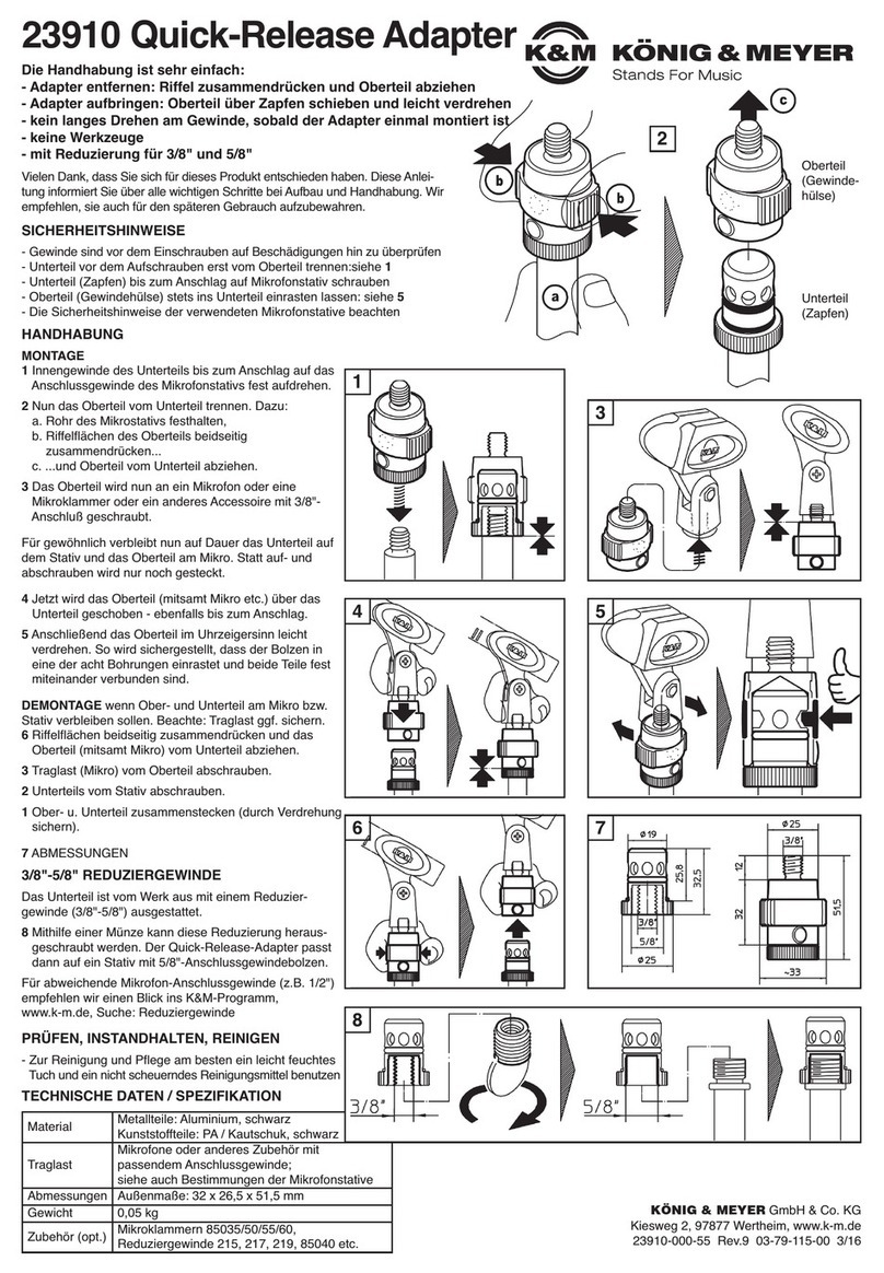
1. BESTANDTEILE
Nach dem Auspacken bitte Sichtprüfung vornehmen, ob alle
Teile vorhanden - und soweit erkennbar - unbeschädigt sind.
SCHWENKGELENK:
aPilz 3/8" (5/8"), bGummischeibe ø 40 mm (2x),
cKnebelmutter M8, dU-Scheibe ø 24 mm, eSchwenkgelenk,
fSchlossschraube M8 x 30 mm, gHebel des Schnellverschlusses
ADAPTERPLATTE:
hHutmutter M5, iU-Scheibe ø 10 mm, jPlattenhalterung,
kAdapterplatte
2. ZUSAMMENBAU des 19685
2.1 Beutel vom Gewinde abziehen; Knebelmutter c
2.1 entnehmen und auf das Gewinde schrauben.
2.2 Obenliegenden Hebel gdes Schnellverschlusses
2.2 betätigen. Dadurch fährt der Dorn zurück.
2.3 Nun die Steckplatte des Gelenks ebis zum
2.3 Anschlag in die Plattenhalterung jschieben.
2.4 Hebel gloslassen, wodurch der Dorn in die
2.4 Freimachung der Plattenhalterung jeintaucht und
2.4 die Verbindung sichert.
2.4 HINWEIS:
2.4 Erst durch erneutes Betätigen des Hebels gkann
2.4 die Adapterplatte kwieder entfernt werden.
3. MONTAGE am HALTER/STATIV
3.1 Rändelscheibe am Stativ bis zum Anschlag auf den
3.1 Gewindebolzen drehen.
3.2 Gelenk nun ebenfalls aufschrauben: ca. 3 Umdrehungen.
3.3 Rändelscheibe wieder zurückdrehen, so dass diese mit
3.3 dem Gelenk spielfrei verspannt ist.
4. BILDSCHIRM an ADAPTERPLATTE BEFESTIGEN
Dazu bieten sich zwei Vorgehensweisen an:
4.A Adapterplatte am Gelenk belassen…
4.a.1 …und mit Bildschirm verschrauben.*
4.B Adapterplatte vom Gelenk entfernen;
4.b.1 dazu Hebel gdes Schnellverschlusses drücken,
4.b.2 Adapterplatte kabziehen…
4.b.3 …und diese mit dem Bildschirm verschrauben*
4.b.4 Anschließend Adapterplatte k(mitsamt Bildschirm)
wieder mit dem Gelenk everbinden - siehe Kapitel 2.2 - 2.4.
* Die Befestigung erfolgt mittels vier Schrauben M4 x …, welche
*jedoch nicht im Lieferumfang enthalten sind, da deren Länge
*von den Abmessungen des jeweiligen Bildschirmes abhängen.
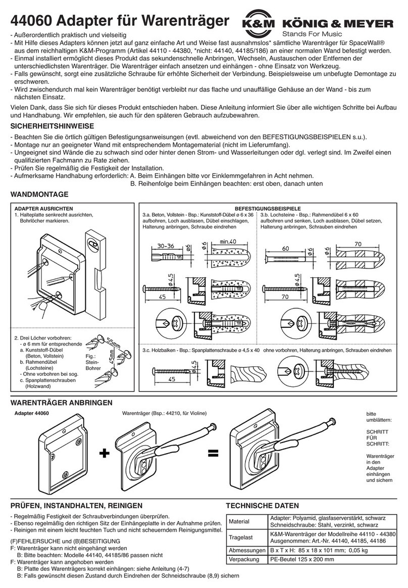
Vielen Dank, dass Sie sich für dieses Produkt entschieden haben. Bitte lesen und
beachten Sie vor Aufbau und Betrieb dieses Produkts sorgfältig diese Anleitung.
Sie informiert Sie über alle wichtigen Schritte bei Aufbau und Handhabung. Wir
empfehlen, sie auch für den späteren Gebrauch aufzubewahren.
AUFSTELLANLEITUNG
- Bitte beachten Sie die Angaben dieser Aufstellanleitung
- Beachten Sie ebenfalls die Sicherheitsanweisungen und
-Anleitungen beteiligter Produkte (Stativ, Bildschirm)
- Max. Tragfähigkeit: 5 kg
- Das verwendete Stativ muss in der Lage sein, die Last des
-Adapters und des Bildschirmes sicher zu tragen; dies gilt
-sowohl für die Tragkraft als auch die Standfestigkeit des
-Stativs (ausreichend großer Fußkreis)
- Der Stativuntergrund muss tragfähig und eben sein
- Auf feste Schraubverbindungen achten und diese in
-regelmäßigen Abständen überprüfen
- Schwenken Sie den Bildschirm nicht in eine Über-Kopf-
-Position, da sich die Prismenverbindung selbständig lösen
-kann, sobald der Rasthebel gelöst wird. Siehe Abb.: 6.3.4.1
- Vor Nässe schützen
- Beschädigte Teile müssen ersetzt werden
1. BESTANDTEILE
2. ZUSAMMENBAU
3. MONTAGE am HALTER/STATIV
4. BILDSCHIRM an ADAPTERPLATTE BEFESTIGEN
19685 Adapter für Bildschirme
- Adapter zur Befestigung kleiner LCD/LED Bildschirme an einem Stativ, z.B.:
-Keyboardständer:
-- 18810/20 »Omega« (via Universalhalter 18807, 18817)
-- 18840/60 »Spider Pro« (direkt oder via 18872, 18873),
-- 18930/33/90/97 X-Ständer (via Universalhalter 18944)
-- 18950/53 Klapptische (via Universalhalter 18807, 18817)
-Geräteständer:
-- 18826 (via Universalhalter 18944)
-Mikrofonstative (nicht am Schwenkarm):
-- kommt auf Standfestigkeit an (am besten Tests durchführen)
-- mit Stativ-Anschlussgewinde:
--3/8" (Art.-Nr.19685-300-55) sowie
--5/8" (Art.-Nr.19685-500-55)
- VESA-Adapterplatte: Bohrungsabstand 75 x 75 mm und 100 x 100 mm
- Tragfähigkeit max. 5 kg
- stufenlos verstellbar in Richtung (360°) und Neigung
- Adapterplatte kann über Prismenverbindung schnell und
sicher aufgebracht bzw. wieder abgenommen werden

WARTUNG
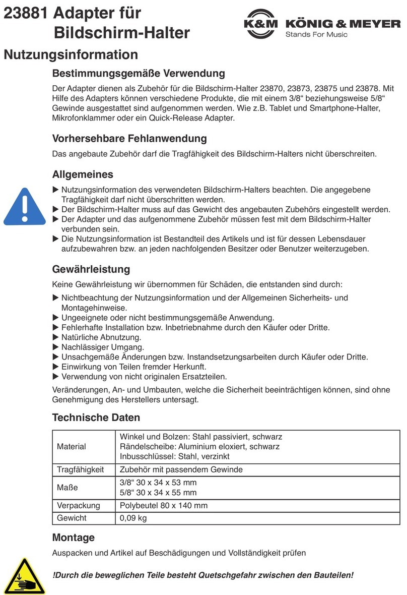
BENUTZERHINWEISE / FUNKTIONEN 5. NEIGUNG
6. RICHTUNG
9. ABMESSUNGEN
5. / 6. / 7. / 8. EINSTELLUNGEN
Im Zusammenspiel mit dem jeweiligen Basisstativ:
- Keyboardständern plus Universalhalterungen
- Geräteständern
- Mikrofonstativen,
kann der 19685 in RICHTUNG, NEIGUNG, HÖHE,
ABSTAND (18817) höchst flexibel eingestellt werden.
HINWEIS:
Achten Sie darauf, dass bei dieser Tätigkeit weder
der Adapter, der Bildschirm noch Beteiligte Schaden
nehmen. Gegebenenfalls empfehlen wir, zuvor die
Adapterplatte (+ Bildschirm) vom Gelenk zu nehmen.
5. NEIGUNG
5.1 Adapterplatte/Bildschirm festhalten
5.2 Knebelmutter lösen und…
5.3 …Adapterplatte stufenlos neigen:
5.3.1 - vertikal 90°,
5.3.2 - nach vorn (ca. 15-40°),
5.3.2.1 HINWEIS: Irgendwann schlägt der
5.3.2.1 Bildschirm am Stativrohr an.
5.3.3 - nach hinten bis in die Horizontale (0°)
5.3.4 - Einstellungen nach hinten über die
5.3.4 - 0°-Horizontale hinaus in den negativen Bereich
5.3.4 - sind möglich, jedoch nicht empfehlenswert.
5.3.4.1 HINWEIS: Die Sicherheit der Verbindung ist
5.3.4.1 durch den Zapfen Zdes Hebels zwar gegeben
5.3.4.1 - es entfällt jedoch die zusätzliche Sicherung
5.3.4.1 -durch die konische Prismenverbindung ST.
5.4 Knebelmutter wieder festziehen.
6. RICHTUNG um 360° stufenlos verdrehbar
6.1 Rändelscheibe aus der Konterung mit dem
6.1 Gelenk lösen und nach unten drehen.
6.2 Adapter nun in die gewünschte Richtung drehen.
6.3 Abschließend Rändelscheibe wieder nach oben
6.3 drehen um die eingestellte Richtung zu fixieren
6.3 und das Gewindespiel zu beseitigen.
HINWEIS:
Wiederholtes Verdrehen des Adapters (nach oben)
könnte ungewollt die Sicherheit der Schraubverbindung
gefährden. Achten Sie auf eine ausreichend tiefe
Verschraubung (mind. 2-3 Umdrehungen).
7. HÖHE (siehe Anleitungen der Stative und Halter)
8. ABSTAND (siehe Anleitung 18817 Universalhalter)
9. ABMESSUNGEN
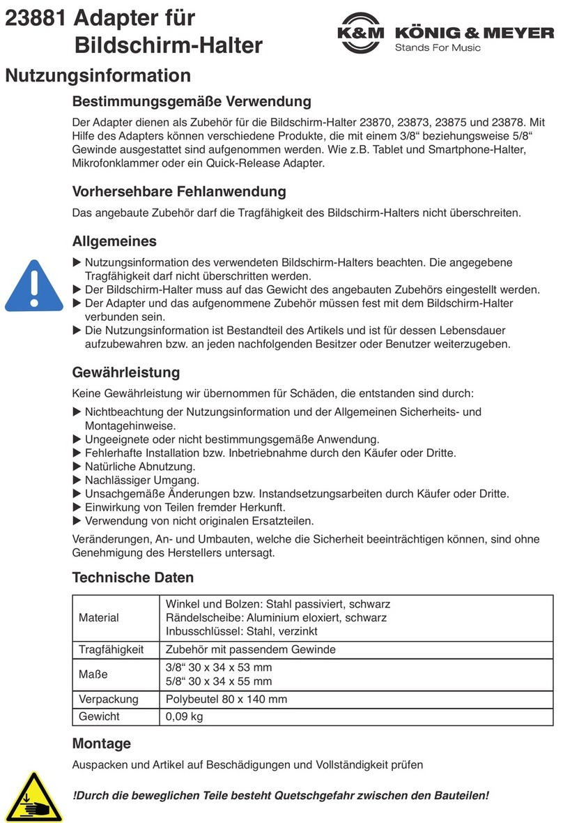
9.1 LOCHBILDER: VESA MIS-D 100 x 100 mm
VESA MIS-D 75 x 75 mm
9.2 ABMESSUNGEN: B x H x T: 115 x 150 x 81 mm
9.3 VERPACKUNG: Karton 150 x 140 x 55 mm
10. AUFBEWAHRUNG
Wenn es der Bildschirmkoffer erlaubt, empfiehlt es
sich, die Adapterplatte am Bildschirm zu belassen.
VORTEIL:
Die Steck-/Zapfenverbindung ermöglicht eine schnelle
und sichere Montage/Demontage des Bildschirmes
und schont seine feinen M4-Gewindebohrungen.
- Schonender Umgang erhält die Funktion, die Tragkraft
-und Langlebigkeit des Adapters.
- Beschädigte Teile dürfen nicht weiterverwendet werden.
-Sie müssen entweder ersetzt bzw. repariert werden.
- Bei Wartungsarbeiten Traglast entfernen und auf
-Gefährdungen (Kippen, Stoßen, Klemmen) achten.
- Zur Reinigung ein leicht feuchtes Tuch und ein nicht
-scheuerndes Mittel benutzen.
KÖNIG & MEYER GmbH & Co. KG
Kiesweg 2, 97877 Wertheim, www.k-m.de
19685-300-55/19685-500-55 Rev.25/24 03-80-125-00 7/23
FEHLERSUCHE (F) und BESEITIGUNG (B)
F: Gewindebolzen des Statives passt nicht zum Adapter
F: B: Passende Gewinde sind: BSW-3/8" bzw. UNS-5/8"-27G
F: B: HINWEIS: M10 könnte mit BSW-3/8" verwechselt werden
F: Verschraubung zwischen Adapter und Stativ wackelt
F: B: Adapter mind. 2-3 Gänge auf das Stativ drehen 3.2
F: B: Rändelscheibe mit Adapter kontern 3.3
F: Bildschirm verändert ungewollt die Neigung
F: B: Traglast zu hoch? Max. 5 kg
F: B: Knebelmutter nachziehen; Zustand der beiden
F: B: Gummischeiben büberprüfen
F: Bildschirm wackelt am Halter
F: B: Festsitz der Prismenverbindung sicherstellen
F: B: Eingriff des Zapfens in die Freimachung sicherstellen
F: B: M4 Befestigungsschrauben am Schirm überprüfen
Material
Adapterplatte, Schwenkgelenk: Stahl, gepulvert
Verschraubung: Stahl, verzinkt
Knebelmutter: Stahl/Kunststoff (PP)
Plattenhalterung, Pilz: Zinklegierung, gepulvert
Klemmscheiben: Gummi mit Gewebeeinlage
Varianten 19685-300-55 (3/8")
19685-500-55 (5/8")
Traglast LCD/LED-Bildschirme, max. 5 kg
Abmessungen Lochbild VESA 75/100
Verpackung Karton: 150 x 140 x 55 mm
vertikal
horizontal
Neigung
nach vorn
(Neigung nach hinten)
- nicht empfohlen -
negativ
SAFETY INSTRUCTIONS
1. COMPONENTS
After unpacking the item, please perform a visual inspection in
order to determine whether all parts are present and, as far as
can be seen, undamaged .
SWIVEL JOINT:
aswivel head 3/8" (5/8"), brubber washer diameter 40 mm (2x),
cT-bar locking screw M8, dwasher diameter 24 mm, eswivel joint,
fcarriage bolt M8 x 30 mm, gquick release lever
ADAPTER PLATE:
hcap nut M5, iwasher diameter 10 mm, jconnecting plate,
kadapter plate
2. ASSEMBLY of the 19685
2.1 Pull the bag off the thread; remove the T-bar locking screw c
2.1 and screw it onto the thread.
2.2 Operate the upper lever gof the quick-release fastener.
2.2 This causes the mandrel to retract.
2.3 Now push the plug-in plate of the swivel joint einto
2.3 the connecting plate jas far as it will go.
2.4 Release lever g, thereby causing the mandrel to enter
2.4 the connecting plate clearance jand secure the connection.
2.4 NOTE:
2.4 The adapter plate kcan be removed only
2.4 by operating the lever gagain.
3. MOUNTING on the HOLDER/STAND
3.1 Turn the knurled washer on the stand as far as it will go
3.1 on the threaded bolt.
3.2 Now also screw the swivel joint on: approx. 3 turns.
3.3 Turn the knurled washer back again so that it is clamped
3.3 to the swivel joint is free from play.
4. ATTACH SCREEN to ADAPTER PLATE
There are two possible approaches to this:
4.A Leave the adapter plate on the swivel joint…
4.a.1 …and screw them together with the screen.*
4.B Remove the adapter plate from the swivel joint;
4.b.1 press the lever gof the quick-release fastener to do this
4.b.2 pull off the adapter plate k…
4.b.3 …and screw them to the screen*
4.b.4 Then reconnect the adapter plate k(together with the screen)
to the swivel joint e- see Chapters 2.2 - 2.4.
* The mounting is done by means of four M4 × … screws. However,
*these are not included in the scope of delivery because their
*length depends on the dimensions of the respective screen.
Thank you for choosing this product. Please read and follow these instructions
carefully before setting up and operating this product. They inform you about all
the important steps involved in setting up and handling. We recommend that you
also keep them for future use.
ASSEMBLY INSTRUCTIONS
- Please observe the information in these installation instructions
- Also observe the safety instructions and instructions of products
-involved (stand, screen)
- Max. load-bearing capacity: 5 kg
- The stand used must be able to safely support the load of
-the adapter and the screen; this applies to both the load-
-bearing capacity and the stability of the stand (sufficiently
-large base diameter)
- The stand base must be load-bearing and level
- Ensure that the screw connections are tight, and check
-them at regular intervals
- Do not swivel the screen into an overhead position because
-the plug-in connection may loosen independently as soon as
-the latching lever is released. See Figure: 6.3.4.1
- Protect from moisture
- Damaged parts must be replaced
1. COMPONENTS
2. ASSEMBLY
3. MOUNTING on the HOLDER/STAND
4. ATTACH SCREEN to ADAPTER PLATE
19685 Adapter for screens
- Adapter for attaching a small LCD/LED LCD/LED screens on a stand e.g.:
-Keyboard stands:
-- 18810/20 »Omega« (via Universal holder 18807, 18817)
-- 18840/60 »Spider Pro« (directly or via 18872, 18873),
-- 18930/33/90/97 X-Ständer (via Universal holder 18944)
-- 18950/53 folding tables (via Universal holder 18807, 18817)
-Equipment stand:
-- 18826 (via Universal holder 18944)
-Microphone stands (not on the boom arm):
-- depends on stability (best to carry out tests)
-- with stand connection thread:
--3/8" (Item no.19685-300-55) as well as
--5/8" (Item no.19685-500-55)
- VESA adapter plate: Hole spacing 75 x 75 mm and 100 x 100 mm
- Load-bearing capacity max. 5 kg
- Continuously adjustable in direction (360°) and inclination
- Adapter plate can be attached and removed quickly and easily
via prismatic connection

MAINTENANCE
USER INSTRUCTIONS / FUNCTIONS 5. TILT
6. DIRECTION
9. DIMENSIONS
5. / 6. / 7. / 8. SETTINGS
In conjunction with the respective base stand:
- Keyboard stands plus universal mounts
- Equipment stands
- Microphone stands,
the 19685 can be adjusted in DIRECTION, TILT,
HEIGHT, and DISTANCE (18817) in a highly flexible way.
NOTE:
Make sure that neither the adapter, the screen, nor
any involved parties are damaged during this activity.
If necessary, we recommend removing the adapter
plate (+ screen) from the joint beforehand.
5. TILT
5.1 Hold adapter plate/screen
5.2 Loosen the T-bar locking screw and…
5.3 …tilt adapter plate steplessly:
5.3.1 - vertically 90°,
5.3.2 - forward (approx. 15-40°),
5.3.2.1 NOTE: At some point the screen
5.3.2.1 will strike the stand tube.
5.3.3 - backward to the horizontal (0°)
5.3.4 - adjustments backwards beyond the
5.3.4 - 0° horizontal into the negative range
5.3.4 - are possible but not recommended.
5.3.4.1 NOTE: The safety of the connection is provided
5.3.4.1 by the pin Zof the lever - however, the
5.3.4.1 additional safety provided by the conical
5.3.4.1 prismatic connection ST is omitted.
5.4 Tighten T-bar locking screw again.
6. DIRECTION steplessly rotatable 360°
6.1 Loosen the knurled washer from the retainer
6.1 with the swivel joint and turn it downward.
6.2 Now turn the adapter in the desired direction.
6.3 Finally, turn the knurled washer up again to fix
6.3 the set direction and eliminate the thread tolerance.
NOTE:
Repeated twisting of the adapter (upwards) could
unintentionally compromise the integrity of the screwed
connection. Make sure that the screw connection is
sufficiently deep (at least 2-3 turns).
7. HEIGHT (see instructions of the stands and holders)
8. DISTANCE
8. (see instructions 18817 Universal holder)
9. DIMENSIONS
9.1 HOLE PATTERNS: VESA MIS-D 100 x 100 mm
VESA MIS-D 75 x 75 mm
9.2 DIMENSIONS: W x H x D: 115 x 150 x 81 mm
9.3 PACKAGING: Carton 150 x 140 x 55 mm
10. STORAGE
If the screen case allows it, it is recommended to
leave the adapter plate on the screen.
ADVANTAGE:
The plug/pin connection enables quick and safe
mounting/disassembly of the screen and protects
its fine M4 threaded holes.
- Gentle handling maintains the function, load-bearing
-capacity, and longevity of the adapter.
- Damaged parts should not be reused.
-They must either be replaced or repaired.
- During maintenance work, remove the load, and check
-for hazards (tipping, bumping, jamming).
- For cleaning, use a slightly damp cloth and a non-
-abrasive agent.
KÖNIG & MEYER GmbH & Co. KG
Kiesweg 2, 97877 Wertheim, www.k-m.de
19685-300-55/19685-500-55 Rev.25/24 03-80-125-00 7/23
FAULT-FINDING (F) and REPAIR (R)
F: Threaded bolt of the stand does not fit the adapter
F: R: Suitable threads are: BSW-3/8" or UNS-5/8"-27G
F: R: NOTE: M10 could be confused with BSW-3/8"
F: Screw connection between adapter and stand wobbles
F: R: Turn adapter at least 2-3 rotations onto the stand 3.2
F: R: Lock knurled washer with adapter 3.3
F: Screen changes tilt unintentionally
F: R: Load capacity too high? Max. 5 kg
F: R: Re-tighten T-bar locking screw; check condition
F: R: of both rubber washers b
F: Screen wobbles on the holder
F: R: Ensure that the prismatic connection is firmly seated
F: R: Ensure engagement of the pin in the clearance
F: R: Check M4 fixing screws on screen
Material
Adapter plate, swivel joint: steel, powder-coated
Screw connection: steel, galvanized
T-bar locking screw: steel/plastic (PP)
Connecting plate, swivel head:
zinc alloy, powdered
Clamping discs: rubber with fabric insert
Variants 19685-300-55 (3/8")
19685-500-55 (5/8")
Load capacity LCD/LED screens, max. 5 kg
Dimensions Hole pattern VESA 75/100
Packaging Carton: 150 x 140 x 55 mm
vertically
horizontal
Inclination
forward
(inclination to the rear)
- not recommended -
negativ
Table of contents
Languages:
Other Konig & Meyer Adapter manuals

Konig & Meyer
Konig & Meyer Quick-Release Adapter 23910 User manual

Konig & Meyer
Konig & Meyer 23881B Specification sheet

Konig & Meyer
Konig & Meyer 19610 User manual

Konig & Meyer
Konig & Meyer 44060 User manual

Konig & Meyer
Konig & Meyer 23900 User manual

Konig & Meyer
Konig & Meyer 19780 User manual

Konig & Meyer
Konig & Meyer 23881 Specification sheet

Konig & Meyer
Konig & Meyer 23900 Specification sheet

Konig & Meyer
Konig & Meyer 19780 User manual