Konig & Meyer 19780 User manual

SICHERHEITSHINWEISE
AUFSTELLANLEITUNG
Vielen Dank, dass Sie sich für dieses Produkt entschieden haben. Bitte lesen und
beachten Sie sorgfältig diese Anleitung. Sie informiert Sie über alle wichtigen Schritte
bei Aufbau und Handhabung. Wir empfehlen, sie auch für den späteren Gebrauch
aufzubewahren.
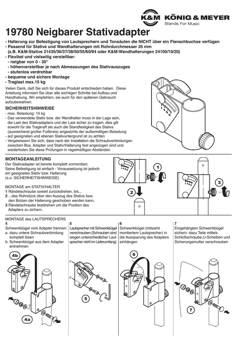
Der Stativadapter ist bereits komplett vormontiert.
Seine Befestigung ist einfach - Voraussetzung ist jedoch
ein geeignetes Stativ bzw. Halterung
(s.o. SICHERHEITSHINWEISE)
1. MONTAGE am STATIV/WANDHALTER
1.a Rändelschraube M8 x 15 mm soweit zurückdrehen, bis...
1.b ...das Rohrstück über den Auszug des Stativs bzw.
1.b den Bolzen der Halterung geschoben werden kann.
1.c Rändelschraube festdrehen um die Position des
1.c Adapters zu sichern.
- Traglast: Lautsprecher bis max.15 kg Gewicht
- Das verwendete Stativ bzw. der Wandhalter muss in der Lage sein, den
-Neigbaren Stativadapter 19780 + Lautsprecher sicher zu tragen. Dies gilt:
-a. für die TRAGKRAFT des Stativs bzw. der Wandhalterung sowie
-b. für die STANDFESTIGKEIT des Stativs.
-b. Ein Maß für die Standfestigkeit ist der Widerstand gegen Seitenkräfte, wie sie
-b. z.B. durch -Wind, -Stöße oder schiefen Untergrund entstehen. Hinzu kommt
-b. beim 19780 bauartbedingt der außermittige Schwerpunkt der Traglast.
-b. Zur Prüfung der Standfestigkeit empfehlen wir die Durchführung des in der
-b. DIN 56950 beschriebenen Kipptestes auf einer um 5° geneigten Ebene.
-b. HINWEIS: Dessen ungeachtet muss das Stativ stets auf einen geeigneten,
-b. HINWEIS: d.h. tragfähigen und ebenen Untergrund aufgestellt werden.
- Vor und nach Gebrauch ist eine Sichtprüfung der Installation
-(19780 + Stativ/Wandhalterung + Lautsprecher) vorzunehmen;
-schadhafte Teile dürfen nicht mehr verwendet werden, d.h. sie müssen
-unverzüglich ersetzt oder repariert werden.
- Vergewissern Sie sich, dass nach der Installation die Schraubverbindungen
-zwischen Box, Adapter und Stativ/Halterung fest angezogen sind und
-wiederholen Sie diese Prüfungen in regelmäßigen Abständen.
- Nur im Innenbereich
2.a Schwenkbügel vom Adapter trennen:
2.a.1 untere Schraubverbindung lösen
2.a.2 Schwenkbügel aus dem Adapter
2.a.2 entnehmen
2.c Schwenkbügel (mitsamt mon-
2.c tiertem Lautsprecher) in die
2.c Aussparung des Adapters
2.c einhängen
2.d Eingehängten Schwenkbügel
2.d sichern: dazu Teile mittels Schloß-
2.d schraube, U-Scheiben und
2.d Sicherungsmutter verschrauben
2.b Lautsprecher mit Schwenk-
2.b bügel verschrauben
2.b.1 Schrauben sind wegen
2.b.1 unterschiedlicher Laut-
2.b.1 sprecher nicht im Liefer-
2.b.1 umfang
MASSNAHMEN
zur Steigerung
der Standsicherheit:
1. AUSTRICHTUNG
1. des Lautsprechers
1. direkt über einem
1. der Standrohre
2. ABSENKUNG
2. der Traglast
2. MONTAGE des LAUTSPRECHERS - DIREKT, ohne Adapterplatte (bei passendem Anschlußmaß: 70-76,2 mm)
19780 Neigbarer Stativadapter
- Halterung zur Befestigung von Lautsprechern und Tonsäulen,
-die NICHT über ein Flanschbuchse verfügen. Passend für:
-- Stative mit Auszügen ø35 mm
--(z.B. K&M-Stative 21435/36/37/38/50/55/60/94)
-- Wandhalterungen mit Bolzen ø35 mm (K&M 24100/40/50)
- Flexibel einstellbar: Neigung von 0 - 30° / Richtung: stufenlos 360°
- bequeme und sichere Montage
- Traglast max.15 kg
F: Produkt lässt sich nicht auf das Stativ/Halter schieben
F: B: Stativrohr/Wandhalter-Bolzen zu groß (ø36, ø38 mm) oder deformiert: Austausch oder
F: B: Reparatur erforderlich
F: B: Rohrstutzen vom 19780 deformiert: Austausch oder Reparatur erforderlich
F: Lautsprecher verändert ungewollt die Neigung
F: B: Flügelmutter nachziehen oder Traglast überschritten
F: Lautsprecher wackelt B: Schraubverbindung Lautsprecher-Schwenkbügel überprüfen
F: B: Schraubverbindung Schwenkbügel-Rohrhalter prüfen
BENUTZERHINWEISE / FUNKTIONEN
FEHLERSUCHE (F) und BESEITIGUNG (B)
- Bei Wartungsarbeiten bestehen evtl. aufgrund von: Kanten, gelösten Verbindungen und
-beweglichen Teilen, Gefährdungen durch Quetschen und Stoßen; zur Vermeidung ist mit
-gebotener Vorsicht und ggf. Handschuhen zu arbeiten
- Prüfen Sie regelmäßig den: a. Festsitz der Schraubverbindungen
- Prüfen Sie regelmäßig den: b. ordnungsgemäßen Zustand der Bauteile sowie der kompletten
- Prüfen Sie regelmäßig den: b. Installation (19780, Stativ/Halterung, Box)
- Zur Reinigung ein leicht feuchtes Tuch und ein nicht scheuerndes Reinigungsmittel benutzen
WARTUNG, PFLEGE
TECHNISCHE DATEN
KÖNIG & MEYER GmbH & Co. KG
Kiesweg 2a, 97877 Wertheim, www.k-m.de
19780-018-55/76 Rev.01 03-80-133-00 7/19
Material
Bügel, Rohre: Stahl, gepulvert schwarz
Verschraubung: Stahl, verzinkt
Griffe, Kappe, Scheiben: Kunststoff (PA)
Traglast Lautsprecher, Tonsäulen: max. 15 kg
Karton 160 x 150 x 60 mm
Maße 59 x 87 x 131 mm - 0,54 kg
Neigung: 0° bis -30° stufenlos
3.a Adapterplatten werden benötigt um abweichende Anschlußmaße am Lautsprecher
3.a zu überbrücken. KÖNIG & MEYER bietet eine große Auswahl an Adapterplatten an:
4. & 5. EINSTELLUNGEN
4. NEIGUNG:
4. 0º bis -30°
4.a Lautsprecher halten
4.b Flügelmutter lösen
4.c Lautsprecher neigen
4.d Sichern durch
4.d Festdrehen der
4.d Flügelmutter
5. RICHTUNG:
5. 360° rundum
5.a Lautsprecher festhalten
5.b Rändelschraube lösen
5.c Lautsprecher drehen
5.d Sichern durch
5.d Festdrehen der
5.d Rändelschraube
(Schrauben M6 x 14 nur bei
AP 6 im Lieferumfang; jedoch
nicht bei AP 1-5, da je nach
Lautsprecher unterschiedliche
Schrauben erforderlich sind.)
3.b Die passende Adapterplatte mit
3.b beiden Sicherungsmuttern fest an
3.b den Schwenkbügel schrauben.
Dazu die
zuvor gelöste
Verschraubung
2.a.1 verwenden
Bsp.:
24359
AP 6
3.c Lautsprecher mit der Adapterplatte
3.c verschrauben.
3.d Schwenkbügel (mit montiertem
3.d Lautsprecher) in die Aufnahme
3.d einhängen.
3.d Eingehängten Schwenkbügel sichern mittels
3.d Schloßschraube, U-Scheiben und
3.d Sicherungsmutter; Kappe wieder auf-
3.d drücken.
ZUBEHÖR:
2x Sicherungsmutter M6 (bei AP 1-6) siehe 3.b
2x Schrauben M6 x 14 mm + U-Scheiben (nur bei AP 6 - passend zu GENELEC Ser.8000) siehe 3.c
3. MONTAGE des LAUTSPRECHERS
3. - INDIREKT, mit optional erhältlicher Adapterplatte (AP 1 - AP 6)
Art. 24352
(Adapterplatte 1)
Art. 24354
(AP 2)
Art. 24356
(AP 3)
Art. 24357
(AP 4)
Art. 24358
(AP 5)
Art. 24359
(AP 6)
6. ABMESSUNGEN
B x H x T: 59 x 87 x 131 mm
LOCHBILD:
Der mit dem Lautsprecher
verbundene Schwenkbügel
weist folgendes Lochbild auf:
- Stichmaß 70 - 76,2 mm (= 3")
- Lochdurchmesser 6,2 mm

SAFETY NOTES
MOUNTING INSTRUCTION
Thank you for choosing this product. Please read and follow carefully the instructions.
They inform you about all the important steps regarding set-up and handling. We
recommend to keep the instruction for future reference.
The stand adapter is already completely pre-assembled.
Its mounting is simple - however, the prerequisite is,
that a suitable stand or bracket is used
(see above SAFETY NOTES)
1. MOUNTING to the STAND/WALL BRACKET
1.a Loosen knurled screw M8 x 15 mm until...
1.b ...the tube section can be pushed over the extension
1.b of the stand or the bolt of the bracket.
1.c Tighten the knurled screw to secure the
1.c position of the adapter.
- Load capacity: Loudspeaker up to max. 15 kg weight
- The used stand or wall bracket must be able to carry the Inclinable
-stand adapter 19780 + loudspeaker safely. This applies:
-a. for the LOAD CAPACITY of the stand or the wall bracket as well as
-b. for the STABILITY of the stand.
-b. A measure of stability is resistance to lateral forces such as wind,
-b. impact or inclined surfaces. In addition, the off-centre load gravity
-b. is due to the construction design of the 19780.
-b. In order to test the stability, we recommend carrying out the tilting test
-b. described in DIN 56950 on a level inclined by 5°.
-b. NOTE: Nevertheless, the stand must always be placed on a suitable,
-b. NOTE: i.e. stable and level surface.
- Before and after use, a visual inspection of the installation
-(19780 + stand/wall bracket + loudspeaker) must be carried out;
-defective parts should no longer be used, i.e. they must be replaced
-or repaired immediately.
- Make sure that the screw connections between speaker, adapter
-and stand/bracket are tight after installation and periodically repeat
-these checks.
- Only for indoor use
2.a Disconnect swivel bracket from
2.a adapter:
2.a.1 Loosen lower screw connection
2.a.2 Remove the swivel bracket from
2.a.2 the adapter
2.c Hook the swivel bracket
2.c (including mounted loud-
2.c speaker) into the recess
2.c of the adapter
2.d Secure the hooked-in swivel
2.d bracket: screw the parts together
2.d by using carriage bolt, washers
2.d and locking nut
2.b Screw loudspeaker to
2.b swivel bracket
2.b.1 Because of different loud-
2.b.1 speakers the screws are
2.b.1 not included
MEASURES
to increase stability:
1. APPLICATION of
1. the loudspeaker
1. directly above one
1. of the standpipes
2. DECREASE
2. in load
2. MOUNTING of the LOUDSPEAKER - DIRECTLY, without adapter plate (with suitable connection dimension: 70-76.2 mm)
19780 Inclinable stand adapter
- Holder for the mounting of loudspeakers and column speakers
-that are NOT equipped with a flange adapter. Suitable for:
-- Stands with pull-outs ø35 mm
--(e.g. K&M-Stands 21435/36/37/38/50/55/60/94)
-- Wall brackets with bolts ø35 mm (K&M 24100/40/50)
- Flexible adjustment: Inclination from 0 - 30° / Direction: 360° stepless
- Easy and safe assembly
- Max. load 15 kg

F: Product cannot be slid onto the stand/bracket
F: B: Stand tube/wall bracket bolt too large (ø36, ø38 mm) or deformed: Replacement or
F: B: repair required
F: B: Pipe socket from 19780 deformed: Replacement or repair required
F: Loudspeaker unintentionally changes inclination
F: B: Tighten wing nut or load has been exceeded
F: Loudspeaker wobbles B: Check screw connection between loudspeaker and swivel bracket
F: B: Check screw connection between swivel bracket and pipe holder
USAGE NOTES / FUNCTION
FAULT-FINDING (F) and REPAIR (R)
- Maintenance work may be necessary due to: Edges, detached connections and moving parts,
-danger of crushing and impact; to avoid this, work with due care and gloves if necessary.
- Regularly check the: a. Tight fit of the screw connections
- Regularly check the: b. proper condition of the components and the complete installation
- Regularly check the: b. (19780, stand/bracket, speaker)
- For cleaning, use a slightly damp cloth and a non-abrasive cleaning agent
MAINTENANCE, CARE
TECHNICAL DATA
KÖNIG & MEYER GmbH & Co. KG
Kiesweg 2a, 97877 Wertheim, www.k-m.de
19780-018-55/76 Rev.01 03-80-133-00 7/19
Material
Support arms, tubes: Steel, powder
coating black
Screws: Steel, galvanized
Handles, caps, disks: Plastic (PA)
Load Loudspeakers, sound columns:
max. 15 kg
Box 160 x 150 x 60 mm
Dimensions 59 x 87 x 131 mm - 0.54 kg
Inclination: 0° to -30° stepless
3.a Adapter plates are required in order to allow different connection dimensions on
3.a the loudspeakers. KÖNIG & MEYER offers a large selection of adapter plates:
4. & 5. SETTINGS
4. INCLINATION:
4. 0º to -30°
4.a Hold the loudspeaker
4.b Loosen the wing nut
4.c Tilt loudspeaker
4.d Secure by
4.d tightening
4.d the wing nut
5. DIRECTION:
5. 360° all-round
5.a Hold the loudspeaker,
5.b Loosen the knurled screw
5.c Turning the loudspeaker
5.d Secure by
5.d tightening the
5.d knurled screw
(Screws M6 x 14 only included
with AP 6; but not with AP 1-5,
as different screws are
required depending on the
loudspeaker).
3.b Screw the matching adapter plate
3.b with both locking nuts firmly to the
3.b swivel bracket.
For this purpose
use the previously
loosened screw
connection 2.a.1
e.g.:
24359
AP 6
3.c Screw the loudspeaker to the
3.c adapter plate.
3.d Hook the swivel bracket (with
3.d mounted loudspeaker) into the
3.d receiver.
3.d Secure the hooked-in swivel bracket with
3.d carriage bolt, washers and locking nut;
3.d replace the cap.
ACCESSORIES:
2x locking nuts M6 (for AP 1-6) see 3.b
2x screws M6 x 14 mm + washers (only for AP 6 - suitable for GENELEC Ser.8000) see 3.c
3. MOUNTING of the LOUDSPEAKER
3. - INDIRECT, with optionally available adapter plates (AP 1 - AP 6)
Art. 24352
(Adapter plate 1)
Art. 24354
(AP 2)
Art. 24356
(AP 3)
Art. 24357
(AP 4)
Art. 24358
(AP 5)
Art. 24359
(AP 6)
6. DIMENSIONS
W x H x D: 59 x 87 x 131 mm
HOLE PATTERN:
The with the loudspeaker
connected swivel bracket has
the following hole pattern:
- Spacing 70 - 76,2 mm (= 3")
- Hole diameter 6,2 mm
Table of contents
Languages:
Other Konig & Meyer Adapter manuals

Konig & Meyer
Konig & Meyer 19780 User manual

Konig & Meyer
Konig & Meyer Quick-Release Adapter 23910 User manual

Konig & Meyer
Konig & Meyer 23900 User manual

Konig & Meyer
Konig & Meyer 19685 User manual

Konig & Meyer
Konig & Meyer 19610 User manual

Konig & Meyer
Konig & Meyer 23881 Specification sheet

Konig & Meyer
Konig & Meyer 23900 Specification sheet

Konig & Meyer
Konig & Meyer 44060 User manual

Konig & Meyer
Konig & Meyer 23881B Specification sheet