Konig & Meyer 19780 User manual

19780 Neigbarer Stativadapter
- Halterung zur Befestigung von Lautsprechern und Tonsäulen die NICHT über ein Flanschbuchse verfügen
- Passend für Stative und Wandhalterungen mit Rohrdurchmesser 35 mm
-(z.B. K&M-Stative 21435/36/37/38/50/55/60/94 oder K&M-Wandhalterungen 24100/10/20)
- Flexibel und vielseitig verstellbar:
-- neigbar von 0 - 30°
-- höhenverstellbar je nach Abmessungen des Stativauszuges
-- stufenlos verdrehbar
- bequeme und sichere Montage
- Traglast max.15 kg
SICHERHEITSHINWEISE
MONTAGEANLEITUNG
Vielen Dank, daß Sie sich für dieses Produkt entschieden haben. Diese
Anleitung informiert Sie über alle wichtigen Schritte bei Aufbau und
Handhabung. Wir empfehlen, sie auch für den späteren Gebrauch
aufzubewahren.
Der Stativadapter ist bereits komplett vormontiert.
Seine Befestigung ist einfach - Voraussetzung ist jedoch
ein geeignetes Stativ bzw. Halterung
(s.o. SICHERHEITSHINWEISE)
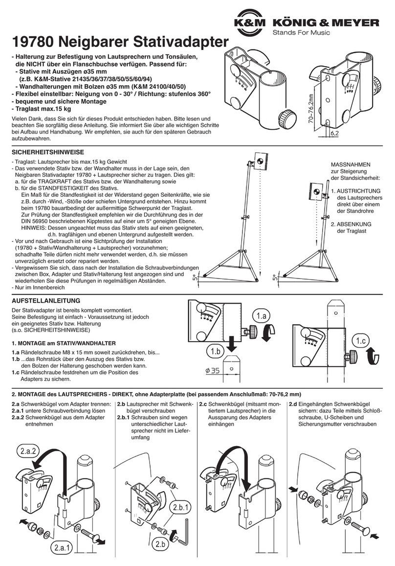
MONTAGE am STATIV/HALTER
1Rändelschraube soweit zurückdrehen, bis...
2...das Rohrstück über den Auszug des Stativs bzw.
2den Bolzen der Halterung geschoben werden kann.
3Rändelschraube festdrehen um die Position des
3Adapters zu sichern.
- max. Belastung: 15 kg
- Das verwendete Stativ bzw. der Wandhalter muss in der Lage sein,
-die Last des Stativadapters und der Last sicher zu tragen; dies gilt
-sowohl für die Tragkraft als auch die Standfestigkeit des Stativs
-(ausreichend großer Fußkreis) angesichts der außermittigen Belastung
- auf geeigneten und ebenen Stativuntergrund ist zu achten
- Vergewissern Sie sich, dass nach der Installation die Schraubverbindungen
-zwischen Box, Adapter und Stativ/Halterung fest angezogen sind und
-wiederholen Sie diese Prüfungen in regelmäßigen Abständen
MONTAGE des LAUTSPRECHERS
4
Schwenkbügel vom Adapter trennen:
a. dazu untere Schraubverbindung
a. komplett lösen
b. Schwenkbügel aus dem Adapter
b. entnehmen
6
Schwenkbügel (mitsamt
montiertem Lautsprecher) in
die Aussparung des Adapters
einhängen
7
Eingehängten Schwenkbügel
sichern: dazu Teile mittels
Schloßschraube,U-Scheiben und
Sicherungsmutter verschrauben
5
Lautsprecher mit Schwenkbügel
verschrauben (Schrauben sind
wegen unterschiedlicher Laut-
sprecher nicht im Lieferumfang)

- Bei Wartungsarbeiten auf evtl. Gefährdungen achten
- Zur Reinigung am besten ein leicht feuchtes Tuch und ein nicht scheuerndes Reinigungsmittel benutzen.
FEHLERSUCHE (F) und BESEITIGUNG (B)
F: Produkt lässt sich nicht auf das Stativ/Halter schieben B: Stativrohr/Haltebolzen haben das falsche Maß oder sind verballert
F: Lautsprecher verändert ungewollt die Neigung B: Flügelmutter nachziehen oder Traglast überschritten
F: Lautsprecher wackelt B: Schraubverbindung zwischen Lautsprecher und Schwenkbügel überprüfen
B: Schraubverbindung zwischen Schwenkbügel und Adapter überprüfen
BENUTZERHINWEISE / FUNKTIONEN
Abmessungen
LOCHBILD:
10 Der mit dem Lautsprecher
10 verbundene Schwenkbügel
10 weist folgendes Lochbild auf:
10 - Stichmaß 70 - 76,2 mm (= 3")
10 - Lochdurchmesser 10,5 mm
ABMESSUNGEN:
11 B x H x T: 59 x 87 x 131 mm
VERPACKUNG
12 PE-Beutel: 200 x 270 mm
PRÜFEN, INSTANDHALTEN, REINIGEN
Kriterien für die Wahl des Stativs bzw. der Halterung ist:
a. deren Rohr- oder Bolzendurchmesser muss 35 mm betragen
b. Bauart und Standsicherheit müssen geeignet sein, die Last des Adapters und des Lautsprechers zu tragen
Geeignete K&M-Stative: 21435/36/37/38/50/55/60/94 Geeignete K&M-Boxenhalterungen: 24100/10/20
STATIVE / HALTERUNGEN
TECHNISCHE DATEN / SPEZIFIKATIONEN
KÖNIG & MEYER GmbH & Co. KG
Kiesweg 2a, 97877 Wertheim, www.k-m.de
19780-000-55 Rev.04 03-80-133-00 11/14
M6 x 40 mm (4x)
Material Bügel, Rohre: Stahl, gepulvert schwarz / Verschraubung: Stahl, verzinkt
Griffe, Kappe, Scheiben: Kunststoff (PA)
Traglast Lautsprecher, Tonsäulen: max. 15 kg
Abmessungen, Gewicht 59 x 87 x 131 mm - 0,54 kg
PE-Beutel; Bruttogewicht 200 x 270 mm - 0,56 kg
Einstellungen
RICHTUNG UM 360° STUFENLOS VERDREHBAR
8a. Lautsprecher festhalten,
8b. Rändelschraube lösen
8c. Lautsprecher in gewünschte Richtung drehen.
8d. Sichern durch Festdrehen der Rändelschraube.
NEIGUNG bis zu 30° STUFENLOS EINSTELLBAR
9a. Lautsprecher festhalten,
9b. Flügelmutter lösen,
9c. Lautsprecher neigen,
9d. Sichern durch Festdrehen der Flügelmutter.
19780 Adjustable stand adapter
- holder for the mounting of loudspeakers and column speakers that are NOT equipped with a flange adapter
- suitable for stand and wall mounts with tube diameters of 35 mm
-(e.g. K&M-Stands 21435/36/37/38/50/55/60/94 or K&M-Wall Mounts 24100/10/20)
- flexible and easily adjustable:
-- angles from 0 - 30°
-- hight adjustable depending on the dimensions of the stand extension
-- variable adjustment
- fast and easy assembly
- load bearing weight max. 15 kg
SAFETY NOTES
MOUNTING INSTRUCTIONS
Thank you for choosing this product.
The instructions provide directions to all of the important set up and handling
steps. We recommend you keep these instructions for future reference.
The holder comes completely pre-assembled.
Attaching the part is easy - the prerequisite is, however, that
a suitable stand or mount is used
(see above SAFETY NOTES)
MOUNTING to the STAND/HOLDER
1Loosen the finger screw to the point that...
2...the tube can be placed over the stand extension or the
2mount bolt.
3Tighten the finger screw to secure the position of the
3adapter.
- max weight 15 kg
- the stand or wall mount must be able to carry the weight of the stand
-adapter, this applies to the load bearing weight and the sturdiness of the
-stand (large enough area for the legs) considering the weight is centered
- be sure that the surface is suitable and level
- after assembly/mounting ensure that the screw connections between the
-box, adapter and stand/mount are properly tightened and repeat this step
-regularly
MOUNTING THE LOUDSPEAKER
4
Separate the swivel support arm
from the adapter:
a. loosen the lower screw completely
b. remove the swivel support arm
b. from the adapter
6
Swivel support arm (with the
mounted loudspeaker) are
placed into the adapter
7
Secure the swivel support arm
with the carriage bolt, U disks and
nuts
5
Screw the loudspeaker to
the swivel support arm
(screws are not included
due to the different sizes)

- During maintenance work, be aware of potential hazards (pinching, pain).
- It is recommended to use a slightly damp cloth and non-abrasive cleaner for cleaning.
FAULT-FINDING (F) and REPAIR (R)
F: The product cannot be placed on the stand/mount R: Stand tube / mount bolt are the wrong size or are stuck
F: Loudspeaker angle changes inadvertently R: Tighten the wing nut or the load bearing weight has been exceeded
F: Loudspeaker is not stable R: Check the screw connection between the loudspeaker and the swivel support arm
R: Check the screw connection between swivel support arm and the adapter
USAGE NOTES / FUNCTION
Dimensions
TEMPLATE:
10 The swivel support arm that is
10 connected to the loud speaker
10 has the following template
10 - Micrometer 70 - 76.2 mm (= 3")
10 - Hole diameter 10.5 mm
DIMENSIONS:
11 W x H x D: 59 x 87 x 131 mm
Packaging
12 PE-Bag: 200 x 270 mm
CHECK, MAINTENANCE, CLEANING
Criteria for the selection of stands i.e. mounts are:
a. the tube or bolt diameter must be 35mm
b. construction and stand sturdiness must be suitable to carry the weight of the adapter and loudspeaker.
Suitable K&M Stands: 21435/36/37/38/50/55/60/94 Suitable K&M-Speaker Mounts: 24100/10/20
STANDS / MOUNTS
TECHNICAL DATA / SPECIFICATIONS
KÖNIG & MEYER GmbH & Co. KG
Kiesweg 2a, 97877 Wertheim, www.k-m.de
19780-000-55 Rev.04 03-80-133-00 11/14
M6 x 40 mm (4x)
Material Support arms, tubes: Steel, powder coating black / screws steel, galvanized
Handles, caps, disks: Plastic (PA)
max weight Loudspeakers, column speakers: max. 15 kg
Dimensions, weight 59 x 87 x 131 mm - 0.54 kg
PE-Bag; gross weight 200 x 270 mm - 0.56 kg
Adjustments
DIRECTION 360° VARIABLE ADJUSTMENT
8a. Hold the loudspeaker,
8b. loosen the finger screw
8c. Place the loudspeaker in the desired direction.
8d. Secure by tightening the finger screw.
ANGLE VARIABLE ADJUSTMENT UP TO 30°
9a. Hold the loudspeaker,
9b. loosen the wing nut.
9c. Place the loudspeaker at the desired angle,
9d. Secure by tightening the wing nut.
Table of contents
Languages:
Other Konig & Meyer Adapter manuals

Konig & Meyer
Konig & Meyer 19780 User manual

Konig & Meyer
Konig & Meyer Quick-Release Adapter 23910 User manual

Konig & Meyer
Konig & Meyer 23881B Specification sheet

Konig & Meyer
Konig & Meyer 23881 Specification sheet

Konig & Meyer
Konig & Meyer 19610 User manual

Konig & Meyer
Konig & Meyer 19685 User manual

Konig & Meyer
Konig & Meyer 44060 User manual

Konig & Meyer
Konig & Meyer 23900 User manual

Konig & Meyer
Konig & Meyer 23900 Specification sheet