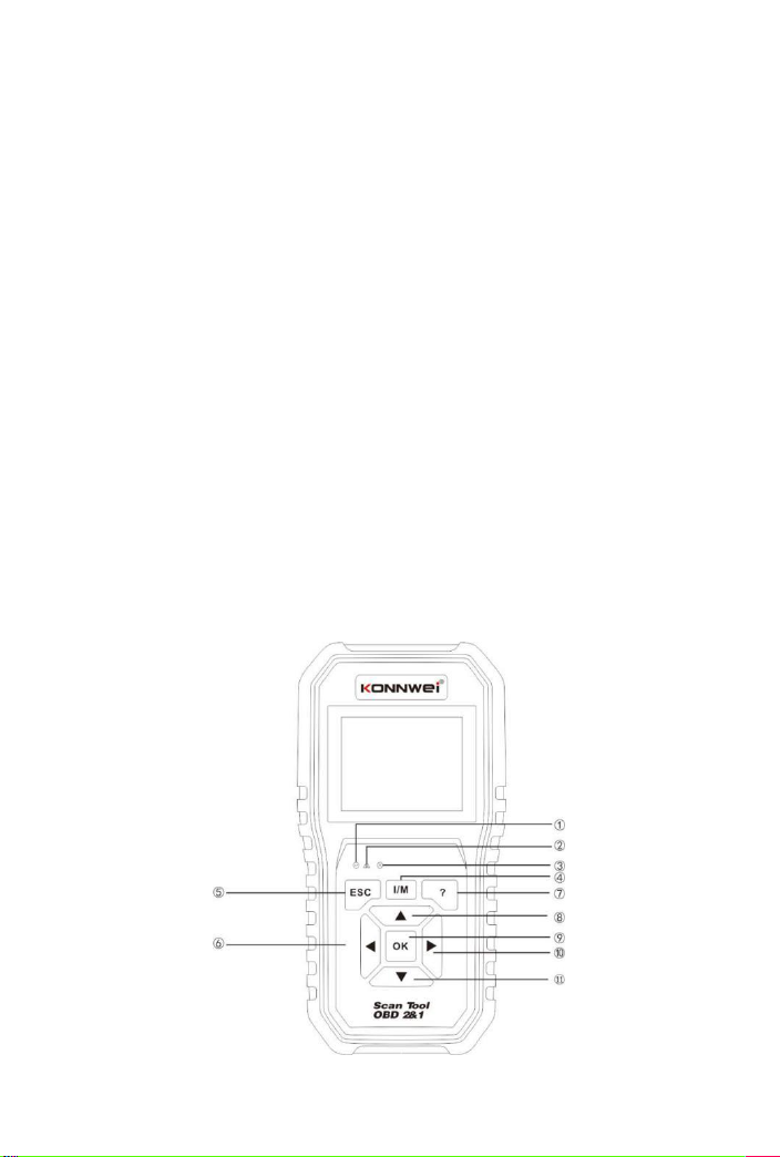
Konnwei KW450 User manual

VW Audi Seat Skoda Full System

1
1.Safety Precautions and Warnings
To prevent personal injury or damage to vehicles and/or the scan tool,
read this instruction manual first and observe the following safety
precautions at a minimum whenever working on a vehicle:
1) Always perform automotive testing in a safe environment.
2) Wear safety eye protection that meets ANSI standards.
3) Keep clothing, hair, hands, tools, test equipment, etc. away from all moving or
hot engine parts.
4) Operate the vehicle in a well-ventilated work area: Exhaust gases are
poisonous.
5) Put blocks in front of the drive wheels and never leave the vehicle unattended
while running tests.
6) Use extreme caution when working around the ignition coil, distributor cap,
ignition wires, and spark plugs. These components create hazardous voltages
when the engine is running.
7) Put the transmission in PARK (for automatic transmission) or NEUTRAL (for
manual transmission) and make sure the parking brake is engaged.
8) Keep a fire extinguisher any test equipment while the ignition is on or the
engine is running.
9)Keep the scan tool dry, clean, free from oil/water or grease. Use a mild
detergent on a clean cloth to clean the outside of the scan tool when necessary.
2.Description

2
1)
OBD II CONNECTOR - Connects the scan tool to the vehicle’s
Data Link Connector(DLC).
2)
LCD DISPLAY - Displays menus and test results.
①GREEN LED - Indicates that engine systems are running normally (The
number of monitors on the vehicle which are active and performing their
diagnostic testing is in the allowed limit, and no DTCs are present).
②YELLOW LED - Indicates there is a possible problem.A “pending” DTC is
present and/or some of the vehicle’s emission monitors have not run their
diagnostic testing.
③RED LED -Indicates there is a problem in one or more of the vehicle’s
systems. The red LED is also used to show that DTCs are present. DTCs are
shown on the Scan Tool’s emission monitors have not run their diagnostic
testing.
④One - Click I/M Readiness Key - Quick-checks State Emissions
readiness and drive cycle verification.
⑤ESC BUTTON - Returns to previous menu.
⑥LEFT SCROLL BUTTON - Move cursor left for selection, or turn page up
when more than one page is displayed.
⑦HELP BUTTON - Provides help information and Code Breaker function.
⑧UP SCROLL BUTTON-Move cursor up for selection.
⑨OK BUTTON - Confirm a selection(or action)from a menu list.
⑩RIGHT SCROLL BUTTON-Move cursor right for selection, or turn page
down when more than one page is displayed.
⑪DOWN SCROLL BUTTON - Move cursor down for selection.
USB CONNECTOR - Connects the scan tool to the PC for printing and
upgrading.
3. Specifications
1)Display: TFT color display (320 x 240 dpi)
2)Operating Temperature: 0 to 60°C (32 to 140 F° )
3) Storage Temperature: -20 to 70°C (-4 to 158 F° )
4)External Power : 8.0 to 18.0V power provided via vehicle battery
5)Dimensions:
Length Width Height
199mm (7.83〃) 104. 5mm(4. 11" ) 37. 5mm(1. 48")
6) weight: 0. 28kg(without wire) 0.484kg(with wire)

3
4. Connection and Settings
4.1 Location of the Data Link Connector(DLC)
The DLC (Data Link Connector or Diagnostic Link Connector) is typically a
16-pin connector where diagnostic code readers interface with the vehicle's
on-board computer. The DLC is usually located 12 inches from the center of the
instrument panel(dash), under or around the driver's side for most of the vehicle.
If Data Link Connector is not located under the dashboard, a label should be
there to tell it's the location. For some Asian and European vehicles, the DLC is
located behind the ashtray and the ashtray must be removed to access the
connector. If the DLC cannot be found, refer to the vehicle's service manual for
the location.
4.2 Setting
1)
Tum the ignition off.
2)
Locate the vehicle's 16-pin Data Link Connector(DLC)
3)
Plug the OBD 11 cable into the vehicle'sDLC.
4)
Turn on the ignition and engine fully
5)
After finishing, press
ESC
button enter Main Menu as
following
CAUTION: Don't connect or disconnect any test equipment with ignition on
or engine running 。

4
5.VW Diagnose
This function is specially designed to diagnose the 101 electronic control
systems of a single vehicle Model
In Figure, select [for VW] or [for AUDI], and press [OK] , the system will display
following screen:
5.1 Common control unit

5
This function is a common control system fault code , data stream and version
reading, and clear fault code.
5.2 All control unit
This function is all control system fault code , data stream and version reading,
and clear fault code.
5.3 System control unit
This function is to scan the common system one by one and read if there is a
fault and display
5.4 Gateway scan
This gateway can quickly scan the ECU of the vehicle (some vehicles have their
own gateway system, tool can get the ECU information of the vehicle by talking
with the gateway which ECU is supported and whether there are a fault)
5.5 Special function
1) Oil Reset
This function allows you to perform reset for the engine oil life system, which
calculates an optimal oil life change interval depending on the vehicle driving
conditions and climate.
This function can be performed in the following cases:
1. If the service lamp is on, you must provide service for the car. After
service, you need to reset the driving mileage or driving time so that the
service lamp turns off and the system enables the new service cycle.
2. After changing engine oil or electric appliances that monitor oil life.
You need to reset the service lamp.
2 ) EPB Reset
1.
If the brake pad wears the brake pad sense line, the brake pad
sense line sends a signal sense line to the on-board computer to replace
the brake pad. After replacing the brake pad, you must reset the brake pad.
Otherwise, the car alarms.
2.
Reset must be performed in the following cases:
a)
The brake pad and brake pad wear sensor are replaced.
b)
The brake pad indicator lamp is on.
c)
The brake pad sensor circuit is short, which is recovered.
d)
The servo motor is replaced.

6
3 ) DPF
DPF regeneration is used to clear PM (Particulate Matter) from the DPF filter
through continuous combustion oxidation mode (such as high temperature
heating combustion, fuel additive or catalyst reduce PM ignition combustion) to
stabilize the performance.
DPF regeneration may be performed in the following cases:
a)
The exhaust back pressure sensor is replaced.
b)
The PM trap is removed or replaced.
c)
The fuel additive nozzle is removed or replaced.
d)
The catalytic oxidizer is removed or replaced.
e)
The DPF regeneration MIL is on and maintenance is performed.
f)
The DPF regeneration control module is replaced.
4 ) BAT Match
This function enables you to perform a resetting operation on the monitoring unit
of vehicle battery, in which the original low battery fault information will be
cleared and battery matching will be done.
Battery matching must be performed in the following cases:
a)The main battery is replaced. Battery matching must be performed to clear
original low battery information and prevent the related control module from
detecting false information. If the related control module detects false
information, it will invalidate some electric auxiliary functions, such as automatic
start & stop function, sunroof without one-key trigger function, power window
without automatic function. b)Battery monitoring sensor. Battery matching is
performed to re-match the control module and motoring sensor to detect battery
power usage more accurately, which can avoid an error message displaying on
the instrument panel.
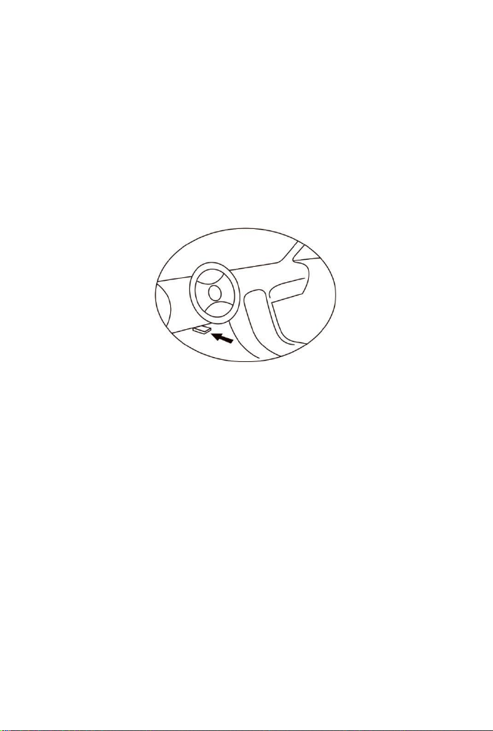
5 ) SAS
To reset the steering angle, firstly find the relative zero point position for the car
to drive in straight line. Taking this position as reference, the Ecu can calculate
the accurate angle for left and right steering.
After replacing the steering angle position sensor, replacing steering mechanical
parts(such as steering gearbox, steering column, end tie rod,steering
knuckle),performing four-wheel alignment, or recovering car body, you must
reset the steering angle;
6 ) Injector Coding
Functions performed after replacing the fuel injector;
generating a new code for a reconditioned injector.

7
Injector is replaced;a
7 ) Throttle Match
Adjust the throttle angle;
(1) After replacing the electronic control unit
(2) After the electric control unit is powered off;
(3) After replacing the throttle body;
(4) After replacing or disassembling the air inlet;
(5) After cleaning the throttle body
8) Suspension
Adjust the height of the air suspension. This function is only applicable to the
models with the air suspension system and the chassis type (VIN seven or eight
digits) as follows:
Volkswagen Touareg (7L), Audi A6 (4F), Audi A8 (4E), Audi Q7 (4L), Audi A6 (C5,
4B) station wagons are not applicable.
9 ) Lamp adjust
The Headlamp Must Be Adjusted Under Following conditions:
1.The Headlamp Range Adjustment Controlunit-J431/-J745Has Been
Reinstalled Or Recorded.
2.One headlamp has been installed after removed one.
3.One headlamp range adjustment servo motor - V48/-V49 has been replaced.
4.The left rear vehicle height sensor - G76 has been replaced.
5.The left front vehicle height sensor - G78has been replaced.
6.One new vehicle height sensor support has been installed.
7.The vehicle subframe or suspension arm (With vehicle height sensor)has
been replaced.
6 OBDII/EOBD Engine System Diagnostics
6.1 Vehicle Coverage
The scan tool is specially designed to work with all OBD II compliant vehicles,
including control area network (CAN), it is required by EPA that all 1996 and
newer vehicles (Cars and light trucks) sold in the united states must be OBD II
compliant and this includes all american, asian and European vehicles.
A small number of 1994 and 1995 model year gasoline vehicles are OBD and
compliant.
To verify if a 1994 or 1995 vehicle is OBD II compliant,check the vehicle

8
emissions control information(VECI) Label, which is located under the hood or
by the radiator of most vehicles. If the vehicle is OBD II compliant, the label will
designate “OBD II Certified’’。Additionally,Government regulations mandate that
all OBD II compliant vehicles must have a “common” sixteen-pin Data Link
Connector (DLC)
For the vehicle to be OBD II compliant is must have a 16-pin DLC (Data Link
Connector) under the dash and the vehicle emission control information label
must state that the vehicle is OBD II compliant .
6.2 OBDII Diagnostic Menu
This option presents a quick way to check for DTCs, isolate the cause of the
illuminated Malfunction Indicator Lamp(MIL), check monitor status prior to
emissions certification testing, verify repairs, and perform a number of other
services that are emission-related.
Select [Diagnostics] and then press [OK], the system will enter the following
screen:
When connected to the car ECU communication, the system will enter the
following screen:

9
6.3 Function:
It mainly includes the following functions:
1) Read Codes
This option is used to identify which section of the emission control system has
malfunctioned.
2) Erase Codes
After reading the retrieved codes from the vehicle and certain repairs have been
carried out, you can use this function to erase the codes from the vehicle. Before
performing this function, please be sure the vehicle's ignition key is in the ON
position with the engine off.
NOTES:
A. Before performing this function, make sure to retrieve and record the trouble
codes.
B. After clearing, you should retrieve trouble codes once more or turn the
ignition on and retrieve codes again. If there are still some trouble codes in the
system, please troubleshoot the code using a factory diagnosis guide, then clear
the code and recheck.
3) Live Data
This option retrieves and displays live data and parameters from the vehicle's
ECU.
4) View Freeze Frame
When an emission-related fault occurs, certain vehicle conditions are recorded
by the on-board computer. This information is referred to as freeze frame data.
Freeze Data is a snapshot of the operating conditions at the time of an
emission-related fault.
Note: If DTCs were erased, Freeze Data may not be stored in vehicle memory
depending on the vehicle.
5) I/M Readiness
I/M refers to Inspection and Maintenance that is legislated by the Government to
meet federal clean-air standards. I/M Readiness indicates whether or not the
various emissions-related systems on the vehicle are operating properly and are
ready for Inspection and Maintenance testing.
The purpose of the I/M Readiness Monitor Status is to indicate which one of the
vehicle's Monitors have run and completed their diagnosis and testing, and
which ones have not yet run and completed testing and diagnosis of their
designated sections of the vehicle's emissions system.
I/M Readiness Monitor Status function also can be used(after repair of a fault
has been performed) to confirm that the repair has been performed correctly,
and/or to check for Monitor Run Status.
6) O2 Monitor Test

10
The results of the O2 sensor test are not live values but instead the results of the
ECU's last O2 sensor test, for live O2 sensor readings.
Not all test values are applicable to all vehicles. Therefore, the list generated will
vary depending on vehicle. In addition, not all the vehicles support the Oxygen
Sensors screen.
7) On-Board Monitor Test
This function can be utilized to read the results of on-board diagnostic
monitoring tests for specific components/systems.
8) Component Test
The Component Test function lets you initiate a leak test for the vehicle's
Component system. The tool does not perform the leak test, but signals to
vehicle's on-board computer are to initiate the test, Before using the system test
function, refer to the vehicle's service repair manual to determine the procedures
necessary to stop the test.
9) Vehicle Info
This option displays the vehicle information, such as VIN(Vehicle Identification
Number), CID(Calibration ID) and CVN(Calibration Verification Number).
10 ) BAT Check
11 ) Modules Present
This option displays the vehicle communication protocol type.
12 ) DTC Lookup
This option you can enter the fault code and view the detailed description.
13 ) Review Data
This option can replay failures that store records.
14 ) Print Data
This option can upload the stored fault code to the computer.
7. Update & Upgrade

11
7.1 This function allows you to update the tool software.
To update your tool, you need the following items.
1. scan tool
2. A PC or laptop with USB ports
3. USB cable
1) Download the application UPlink.exe from our website: www.konnwei.com
2) Run UPlink.exe in your computer(Mac iOS and Linux does not compatible)
3) Press any button until the USB cable is connected with computer and release
it after the tool display a message“Update mode"
4) Open the UPlink software, click "Check Update" button, will download the
upgrade file from the internet then update to tester tool
5) Wait for few minutes until update succeed
6) After the update is completed, restart tester tool finish the whole update See
bellow:
NOTE: when you made a wrong choice and the tool is unable to work properly,
you may need to update the programs. Keep holding any key on the tool for a
long time, and then Connect the tool to the computer via a USB at the same time,
USB cable will force the tool into update mode to refresh the program.
7.2 Service Procedures

Table of contents
Other Konnwei Scanner manuals