KONRAD KT-RFCT 2400A User manual

Copyright © 02.01.2019
Konrad GmbH
D-78315 Radolfzell
KT-RFCT 2400A
User Manual

KT-RFCT 2400A
User Manual – KT-RFCT 2400A Version: 2.0 2/29
This publication contains internal information protected by copyright. All rights reserved.
Photocopying, duplication or translation of this publication, either in full or in part, only with
prior consent from Konrad GmbH. Copyright 2018 Konrad GmbH
Masthead
Konrad GmbH
Fritz-Reichle-Ring 12
D-78315 Radolfzell
Tel. +49 (0) 7732 / 9815-0
Fax +49 (0) 7732 / 9815-104
http://www.konrad-technologies.com
mailto:info@konrad-technologies.com

KT-RFCT 2400A
User Manual – KT-RFCT 2400A Version: 2.0 3/29
Table of Contents
MASTHEAD .................................................................................................. 2
1 WELCOME .............................................................................................. 4
2 UNPACKING THE KT-RFCT 2400A .......................................................... 5
3 DOCUMENTATION.................................................................................. 5
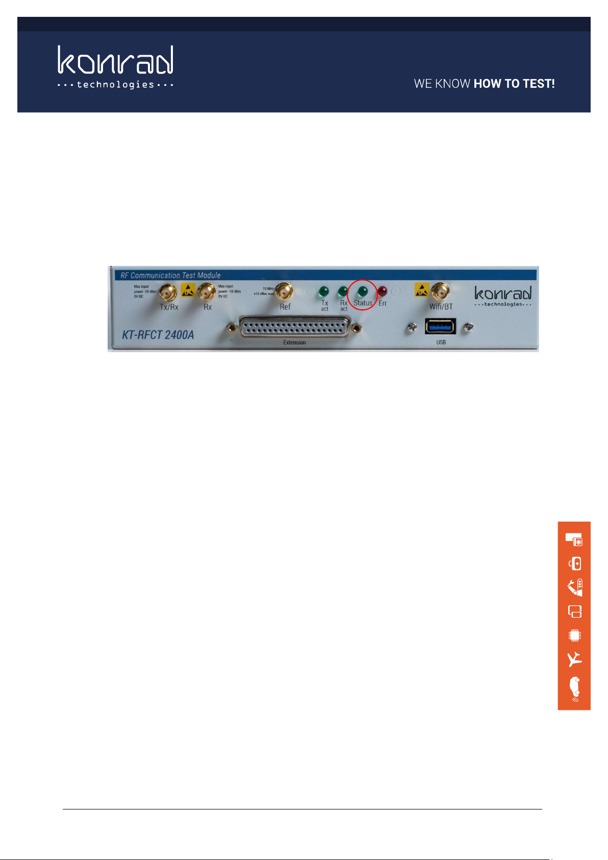
4 FRONT AND REAR PANELS ..................................................................... 7
4.1 Front Panel ............................................................................................ 7
4.2 Rear Panel ............................................................................................. 9
5 HARDWARE SET-UP ............................................................................... 9
5.1 DC power connection .............................................................................. 9
5.2 Power On and Confirmation of Bootup ..................................................... 10
6 SOFTWARE INSTALLATION (FOR WINDOWS) ..................................... 11
6.1 Additional Software Components ............................................................ 12
6.2 Using the Finder APP............................................................................. 13
6.3 Changing the Tester IP Address – (if required) ......................................... 14
7 OPERATION USING THE KT-RFCT 2400A SOFT FRONT PANEL ............. 15
8 CHANGING THE KT-RFCT 2400 FIRMWARE USING THE UPDATER APP. 21
9 ADDITIONAL INFORMATION ............................................................... 26
9.1 Extension Port ..................................................................................... 26
9.2 Rack mount Installation (optional) .......................................................... 27
10 REGULATORY ....................................................................................... 28
11 SUPPORT ............................................................................................. 29
11.1 Calibration ......................................................................................... 29
11.2 Warranty ........................................................................................... 29

KT-RFCT 2400A
User Manual – KT-RFCT 2400A Version: 2.0 4/29
1 Welcome
Welcome to the KT-RFCT 2400A User Manual. The purpose of this document is to provide
information to users to verify device operation and to quickly get up and running with the
device.
Figure 1 –KT-RFCT 2400A
The Konrad-Technologies Radio Frequencies Communication Tester (KT-RFCT 2400A)
provides a low-cost test solution for test of wireless devices. Both RF parametric test and
network throughput performance testing are possible within the same instrument covering
key communication standards such as Bluetooth and Wi-Fi.
Figure 2 – Block Diagram of the KT-RFCT 2400A
The KT-RFCT 2400A Tester has connectors and status indicators on the front panel, but no
actual user controls. The device is controlled remotely over the Ethernet Interface accessed
on the rear of the device. You can use the supplied Konrad KT-RFCT 2400A Tools Software to
configure and control via a Soft Front Panel application. Alternatively, you can control the
test set remotely via software APIs provided by Konrad.

KT-RFCT 2400A
User Manual – KT-RFCT 2400A Version: 2.0 5/29
The User Manual is divided into the following sections:
Unpacking the KT-RFCT 2400A tester
Documentation
Front and Rear panels
Hardware Setup
Software Installation (for Windows users)
Finding the KT-RFCT 2400A on the Ethernet using the Finder APP
Operation using the KT-RFCT 2400A Soft Front Panel
Changing the firmware using the KT-RFCT 2400A Updater
Further Information
Compliance and CE Marking
Regulatory
Konrad Support and Service Information
2 Unpacking the KT-RFCT 2400A
Initial Inspection
Please inspect the shipping container for damage. If the shipping container or packaging
material is damaged it should be kept until the contents have been checked mechanically
and electrically. If there is mechanical damage, notify Konrad Technologies (see page 28 for
further information).
Keep the damaged shipping materials (if any) for inspection by the carrier and a Konrad
representative.
What ships in the Box?
KT-RFCT-2400A when ordered using part number G170125 is supplied inclusive of AC/DC
power converter, CAT6 1m data cable and a Quick Start Guide.
License keys for any purchased options can be obtained by emailing support@konrad-
technologies.de
3 Documentation
KT-RFCT 2400A documentation includes:
The KT-RFCT 2400A User Manual (this guide) – Leads you through unpacking,
checking the tester, powering on the tester and communicating with the device using
the supplied KT Software Application.
The KT-RFCT 2400A Product Datasheet – This contains the detail on the
Specifications and the interfaces available for you to use.
The KT-RFCT 2400A Quick Start Guide – This is supplied in the box and provided a
sub-set of this document.

KT-RFCT 2400A
User Manual – KT-RFCT 2400A Version: 2.0 6/29
The KT-RFCT 2400A Application and Programming Guide – a document providing
detail on how to control and use the device under control from a user developed
software application. (Under Development)
Abbreviations Used in this Guide
APP Software Application
AC Alternating Current
BT Bluetooth
DC Direct Current
DUT Device under test, unit under test, test specimen
IP Internet Protocol
KT Konrad Technologies
PC Personal Computer
RF Radio Frequency
RFCT KT-RFCT 2400A
SMA Sub-Miniature type A – RF connector type
SN Serial Number
USB Universal Serial Bus
Wi-fi Wireless Technology based on IEEE802.11 Standards

KT-RFCT 2400A
User Manual – KT-RFCT 2400A Version: 2.0 7/29
4 Front and Rear Panels
4.1 Front Panel
Figure 3 –KT-RFCT 2400A Front Panel Layout
Description Connector Warning
1 RF input to the non
signaling transceiver
SMA (f) (50
ohms)
Do not exceed -10dBm Max RF power
or 0V DC
Ensure static precautions are taken to
avoid damage through static discharge
2 RF input/output to the non
signaling transceiver
SMA (f) (50
ohms)
Do not exceed -10dBm Max RF power
or 0V DC
Ensure static precautions are taken to
avoid damage through static discharge
3 RF input/output to the Wi-fi
/ Bluetooth radio
SMA (f) (50
ohms)
Do not exceed -10dBm Max RF power
or 0V DC
Ensure static precautions are taken to
avoid damage through static discharge
4 Input for an External
10MHz Reference
SMA (f) (50
ohms)
Do not exceed +15dBm
5
USB 3.0 (for future use but
can be used to provide DC
power)
Type A
6 I/O Extension (see table) D-Sub 37 way
7 Status Indicators
Table 1 – Front Panel Inputs and Output

KT-RFCT 2400A
User Manual – KT-RFCT 2400A Version: 2.0 8/29
4.1.1 Status Indication LEDs
LED
Description
Tx act
Off
–
RF output is in
-
active (Tx/Rx port)
On – RF output is active (Tx/Rx port)
Rx act
Off
–
Signal acquisition is idle (Tx/Rx or Rx port as configured)
On – Signal acquisition in progress (Tx/Rx or Rx port as configured)
Status
Off
–
No DC input power
Flashing – Booting up in progress
On – Ready
Err
Off
–
No error
On –Error Present
Table 2 – Status Indication LED

KT-RFCT 2400A
User Manual – KT-RFCT 2400A Version: 2.0 9/29
4.2 Rear Panel
Figure 4 –KT-RFCT 2400A Rear panel inputs and outputs
D
escription
Connector
Warning
1 12 VDC input
Jack type RAPC722X
2.0 mm center pin
diameter with positive (+)
polarity
Do not exceed +12V DC
Do not apply DC power to
both DC power inputs
simultaneously.
2 12 VDC input Phoenix
Do not exceed +12V DC
Do not apply DC power to
both DC power inputs
simultaneously.
3
Ethernet (1GB)
RJ45 Cat 6
4
Serial Number
Table 3 – Rear panel inputs and outputs
5 Hardware Set-Up
This section will step you through:
Connection of a suitable power supply
Confirmation of boot up
5.1 DC power connection
DC power can be applied to either the Jack input or the Pheonix input from a 12V/3A DC
PSU.
The Pheonix input is best suited to permanent installation in a rack.
DC should not be applied to both simultaneously.

KT-RFCT 2400A
User Manual – KT-RFCT 2400A Version: 2.0 10/29
5.2 Power On and Confirmation of Bootup
When the DC input is connected and tester will power on and all front panel LED’s will
illuminate briefly.
During bootup, the green Status LED will initially flash and then remain on once bootup is
complete.
The KT-RFCT 2400A is then ready for use.
Figure 5 – Bootup Status LED

KT-RFCT 2400A
User Manual – KT-RFCT 2400A Version: 2.0 11/29
6 Software Installation (for Windows)
This section will step you through:
Installation of the KT-RFCT software to your Windows PC
Finding the Tester on the Ethernet using the KT Finder Application
Changing the Tester IP Address – (if required)
The KT RFCT companion software containing instrument drivers, firmware and tools can be
downloaded from:
Link: ftp://195.95.146.157/RFCT/Releases/
Username: read Password: Access2Files
Run the KT-RFCT 2400A software installer and follow on screen prompts.
On completion you may launch the applications from within the start menu or from icons on
the Windows desktop.
A Windows installer installs Windows C/C++ drivers, all optional plugins and a number of
tools: The installer also copies LabVIEW drivers into the correct location for installation.
C/C++ drivers are distributed as 32 bit (x86) and 64 bit (x64) DLLs and have been compiled
using Microsoft Visual Studio 2017.
The DLL import libraries can be found in the “Lib\x86” and “Lib\x64” subfolders.
If you do not have Microsoft Visual Studio 2017, its redistributable package needs to be
installed. This can be downloaded from here:
https://visualstudio.microsoft.com/downloads/
The LabVIEW drivers are copied into the LabVIEW subfolder as VIP files. These files need to
be installed before use using the “VI Package Manager” from JKI. This can be downloaded
from here:
https://jki.net/vipm
KT-RFCT-2400A Tools include:
KT-RFCT 2400A Soft Front Panel for manual instrument control
KT-RFCT-2400A Updater for updating instrument firmware
KT-RFCT 2400 Finder.
Their use has a dependency on National Instruments LabVIEW 2015 runtime. This can be
downloaded from the NI Website http://www.ni.com/downloadllabview-run-time-
engine_2015/5507/en/

KT-RFCT 2400A
User Manual – KT-RFCT 2400A Version: 2.0 12/29
6.1 Additional Software Components
All firmware is pre-installed on the instrument when shipped however, firmware images are
supplied separately for the basic instrument and each optional plugin.
C/C++ drivers are also supplied for Linux OS users. These should be copied/unzipped to
your chosen location.
Drivers
Firmware Tools
C/C++ LabVIEW Python
Windows Linux
RFCT
Installer
.zip
Installer
.zip
.zip
Installer
Optional
Plugins
LE Central
.zip
NA
.zip
NA DTM
.zip
.zip
iPerf
.zip
.zip
Table 4 – Software Package

KT-RFCT 2400A
User Manual – KT-RFCT 2400A Version: 2.0 13/29
6.2 Using the Finder APP
Initially to find and set the IP Address of the KT-RFCT 2400A please follow these steps:
On the Host PC disconnect from all other networks
Connect the Ethernet cable from the KT-RFCT 2400A rear panel LAN port to the Host
PC Ethernet port (for optimal performance use Gigabit LAN and a CAT6 cable)
On the Host PC change the IP Address to static IP address 192.168.0.1
If you wish to add the KT-RFCT 2400A to an existing network please contact your
own IT/Network administrator for advice. The KT-RFCT 2400A can be configured to
use a static IP address or a dynamically allocated IP address via DHCP.
Power on the Tester, then wait until the Status LED stops flashing.
Run the KT-RFCT 2400A Finder application
You press Search to cause the application to search the Subnet for the Tester, the default IP
address is 192.168.0.023

KT-RFCT 2400A
User Manual – KT-RFCT 2400A Version: 2.0 14/29
6.3 Changing the Tester IP Address – (if required)
Using the KT Finder application, you can change IP Address if you require it to be different
from the default value or if you prefer the unit to use a DHCP server to allocate an IP
address.
Power cycle the Tester.
Note: The that by default the tester has three IP addresses; a primary one that can be
changed, and two backup addresses which cannot be changed.
Eth0 (main) 192.168.1.X (where X is related to the device serial number e.g. for
SN2023, X would be 23)
Eth0:0(backup) 192.168.0.23 - Fixed
Eth0:1(backup) 10.102.4.203 - Fixed
Table 6 – Default IP Addresses
If the main IP address is changed to be in the 192.168.0.X or 10.102.4.X subnets, the fixed
backup IP address on the same subnet will be disabled because the tester cannot have two
IP address on the same subnet.

KT-RFCT 2400A
User Manual – KT-RFCT 2400A Version: 2.0 15/29
7 Operation using the KT-RFCT 2400A Soft Front Panel
The Soft Panel Loads and you can prepare to run some basic Non-signaling, Wifi or Bluetooth
tests.
Connect to the KT-RFCT 2400A by entering it’s IP Address
Once connected, the Measurement Tabs are enabled

KT-RFCT 2400A
User Manual – KT-RFCT 2400A Version: 2.0 16/29
7.1.1 Run a loopback test using the supplied Soft Front Panel Application.
Run loopback test on the non-signalling radio (SDR)
Press Generate Waveform Button
Select CW signal. Click Use Selected, then close the popup.

KT-RFCT 2400A
User Manual – KT-RFCT 2400A Version: 2.0 17/29
Now Configure Tx and RX Settings
Tx Configuration Rx Configuration
Frequency = 1.5 GHz Frequency = 1.50005 GHz (note offset value)
Output Power = -20 dBm Reference Level = -10 dBm
Trigger = None Other settings leave as default
Press in the Run window Tx ON and Rx ON
7.1.2 Run a WiFi Scan on the WiFi Tab
Select the WiFi Tab on the Soft Front Panel
In the Client Mode Block select press Enable, then press Scan.

KT-RFCT 2400A
User Manual – KT-RFCT 2400A Version: 2.0 18/29
Note the list of Access Points, select one to connect to, then press Connect.
Press the RSSI to obtain measurements.

KT-RFCT 2400A
User Manual – KT-RFCT 2400A Version: 2.0 19/29
7.1.3 Run a BT Scan on the BT Tab.
Select the BT Tab, Press the Enable button on the Measurement block
Press Scan button, a list of available BT devices will be listed. On a suitable BT device
attempt to pair with the 00_0E_8E_69_69_DC_bluetooth device.

KT-RFCT 2400A
User Manual – KT-RFCT 2400A Version: 2.0 20/29
Once a device is connected as a Client you will see the status change.
Press the RSSI button to obtain measurements when the BT Device is paired with the KT-
RFCT 2400A BT.
Table of contents
Popular Test Equipment manuals by other brands

Fluke
Fluke FiberInspector Pro FI-7000 Getting started guide

Keysight Technologies
Keysight Technologies U3020AD01 User's and service guide

Agilent Technologies
Agilent Technologies 1153A User and service manual

Teledyne Lecroy
Teledyne Lecroy CP030A Operator's manual

Renkforce
Renkforce 6895N operating instructions

NDT
NDT DHT- 200Plus instruction manual