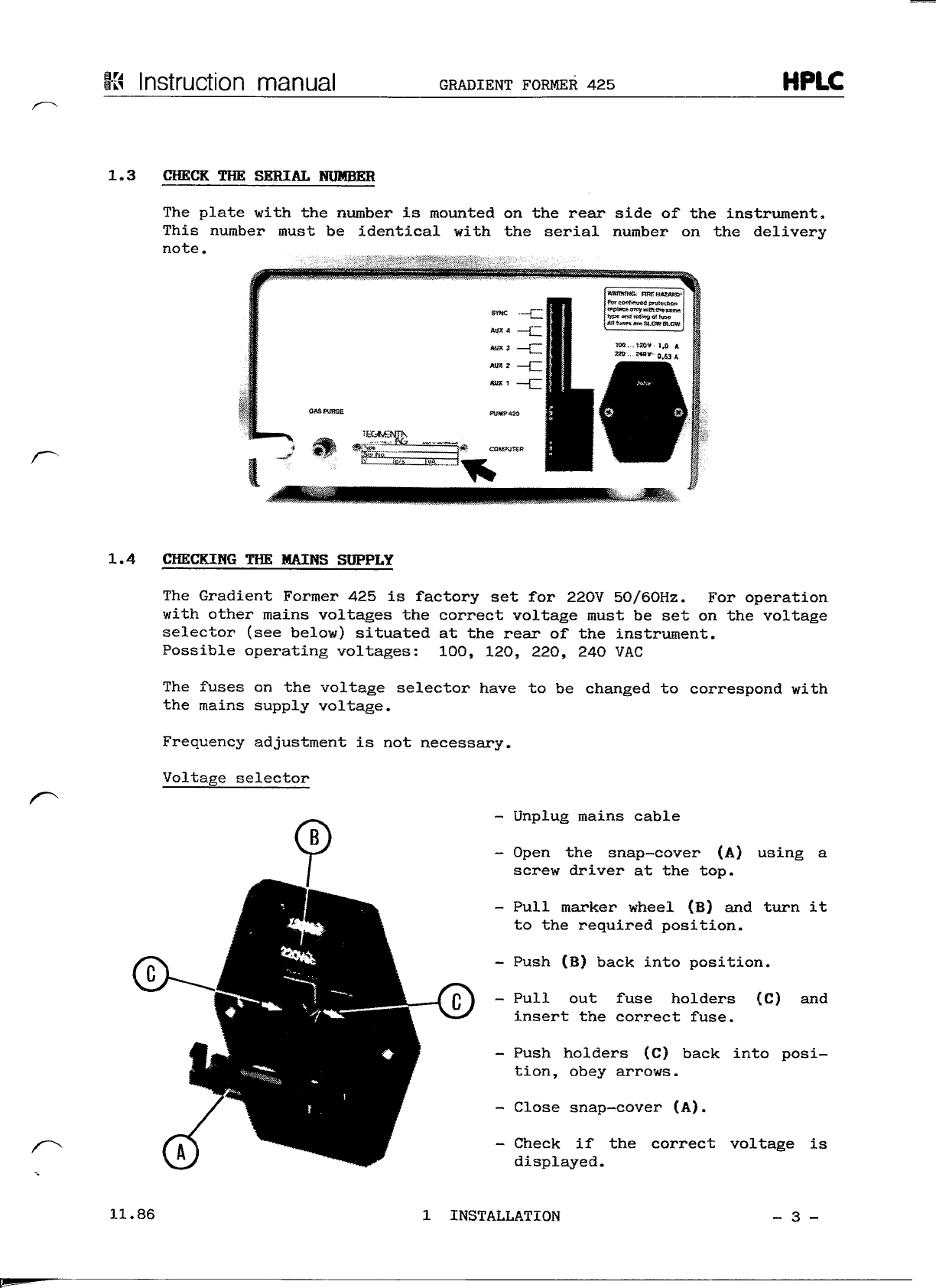
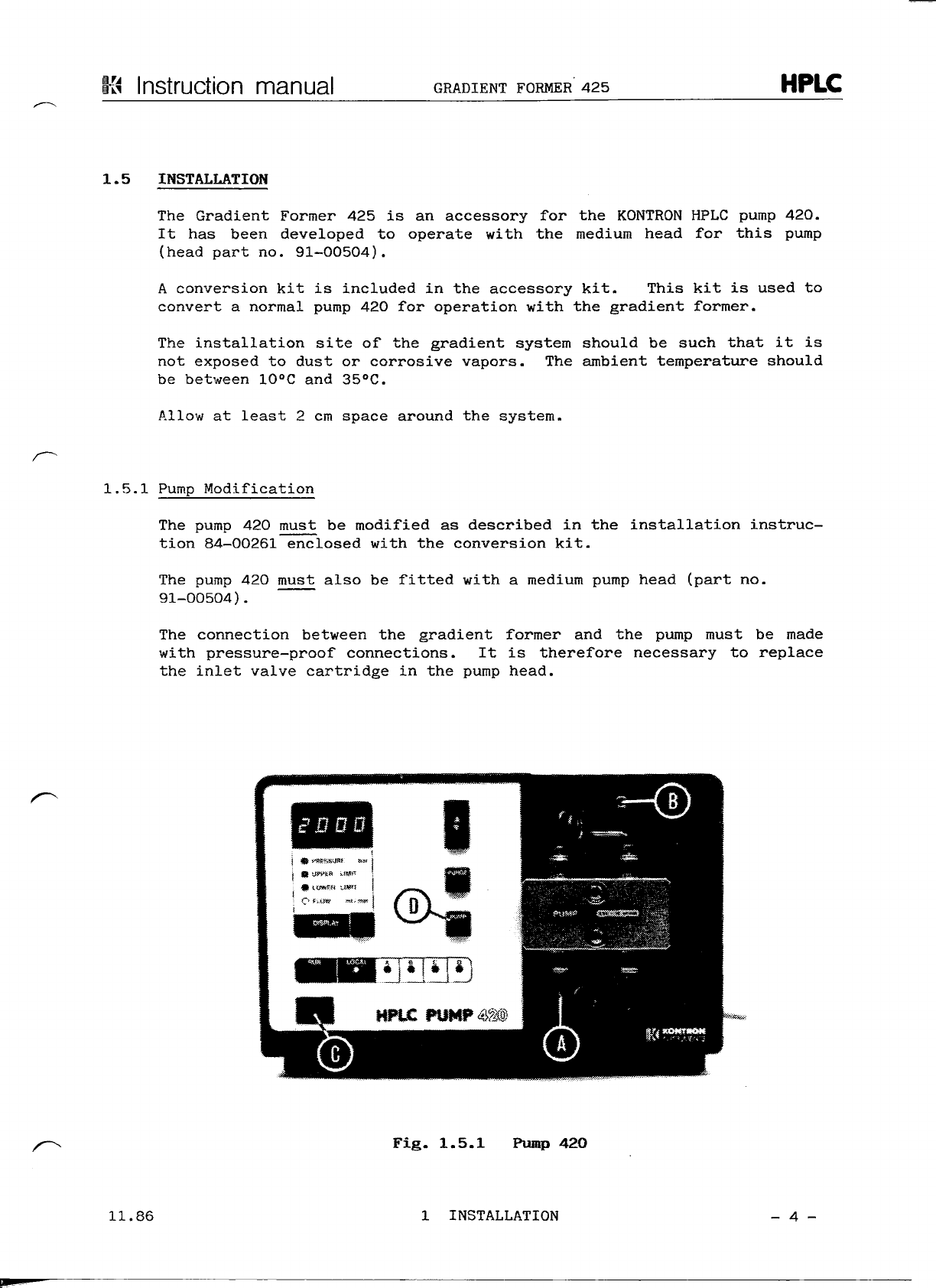
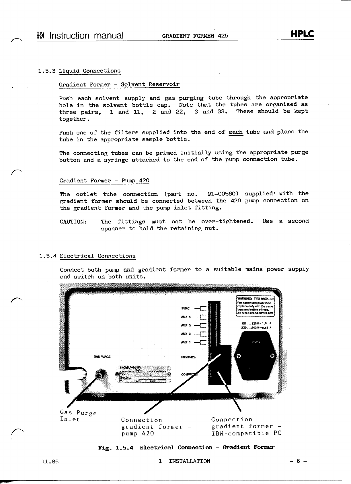
Kontron Instruments HPLC GRADIENT FORMER 425 User manual

IA
KONTRON
INSTRUMENTS
HPLC
GRADIENT
FORMER
Instruction
manual

-K
Instructionmanual
GRADIENT
FORMER
425
HPLC
TABLE
OF
CONTENTS
page
INSTALLATION
1.l
Unpacking
2
1.2
Shipping
list
2
1.3
Checking
the
serial
number
3
*-~\4
Checking
the
mains
supply
3
l.5
Installation
4
1.5.1Pump
modification
4
1.5.2
Installing
the
gradientformer
5
1.5.3
Liquid
connections
6
1.5.4
Electrical
connection
6
1.5.5
Gas
purge
7
1.5.6
Control
Computer
7
2.
INSTRUMENT
DESCRIPTION
Generaldescription
2
2.1
Specifications
2
2.2
Front
panel
3
2.2.1Controls
3
2.2.2Statusdisplay
3
11.86
0
GENERALINFORMATION
- l -

Instruction
manual
GRADIENT
FORMER
425
HPLC
TABLE
OF
CONTENTS
(cont.)
page
OPERATION
3.0
Programmable
parameters
2
3.1
System
start-up
2
3.2
Configuration
3
3.3
Main
command
modes
5
3.4
Manual
mode
6
3.5
File
programming
9
3.5.1Time
9
3.5.2
Flow
9
3.5.3
%A
Step;
%B
Step;
%C
Step
10
3.5.4Sync
10
3.5.5
Auxiliary
11
3.5.6
A
programmingexample
11
3.5.7
General
points
13
3.5.8
Leaving
edit
mode
14
3.6
Saving
and
loading
files
14
3.7
Running
files
14
3.8
SystemStatus
in
file
running
mode
15
4.
TROUBLE
SHOOTING
4.1
Operationerrors
2
4.2
Softwareerror
messages
3
5.
MAINTENANCE
5.1
Routine
maintenance
2
5.2
Spare
parts
3
11.86
0
GENERALINFORMATION
- 2 -

13
Instruction
manual
GRADIENT
FORMER
425
HPLC
TABLE
OF
CONTENTS
page
l.
INSTALLATION
1.l
ünpacking
2
1.2
Shipping
list
2
1.3
Checking
the
serial
number
3
1.4
Checking
the
mainssupply
3
1.5
Installation
4
1.5.1Pump
modification
4
1.5.2
Installing
the
gradientformer
5
1.5.3
Liquidconnections
6
1.5.4
Electrical
connection
6
1.5.5
Gas
purge
7
1.5.6
Control
Computer
7
11.86
l
INSTALLATION
- l -

Ki
Instruction
manual
GRADIENT
FORMER
425
HPLC
TL.
INSTALLATION
1.1
UNPACKING
Compare
the
consignment
with
the
delivery
note.
Both
accessories
and
main
unit
are
packed
ina
singlebox.Check
the
contents
against
the
following
shipping
l
istand
inform
your
local
KONTRON
representative
immediately
should
any
parts
be
missing.
1.2
SHIPPING
LIST
The
following
items
are
included
äs
Standard
accessories:
1
91-00553
GradientFormer
425
2m
07-89023
Gas
supply
tube
1
55-65601
Mains
cable
2
62-13001
Fuse
1.0A
(110V)
2
62-13002
Fuse0.63
A
(220V)
3
66-00452
Solventbottle
l
91-00560
Outlettube
connection
6
92-00910
Inlet
filter
l
92-00904
Inlet
valve
cartridge
(titanium)
l
93-00667
Computercable
l
93-00668
Pump
420
cable
l
95-00196
InstructionmanualincludingSoftware
l
91-00568
Conversion
kit,
pump
420
l
52-69103
Connector,
4way
l
52-69104
Connector,
6 way
03.87
l
INSTALLATION
- 2 -

Instruction
manual
GRADIENT
FORMER
425
HPLC
1.3
CHECK
THE
SERIAL
HUMBER
The
plate
with
the
number
is
mounted
onthe
rear
side
ofthe
Instrument.
This
number
must
be
identicalwith
the
serialnumber
onthe
delivery
note.
1.4
CHECKING
THE
MAINS
SUPPLY
The
GradientFormer
425is
factory
setfor
220V
50/60Hz.
For
Operation
with
other
mains
voltages
the
correctvoltagemust
besetonthe
voltage
selector(see
below)
situated
atthe
rear
ofthe
Instrument.
Possible
operating
voltages:
100,120,220,
240
VAG
The
fuses
onthe
voltageselectorhave
tobe
changed
to
correspondwith
the
mainssupplyvoltage.
Frequency
adjustment
isnot
necessary.
Voltage
selector
-
Unplugmains
cable
-
Open
the
snap-cover
(A)
using
a
screwdriver
atthe
top.
-
Pullmarker
wheel
(B)and
turn
it
to
the
requiredposition.
-
Push
(B)
backintoposition.
-
Pull
out
fuse
holders
(G)
and
insert
the
correctfuse.
-
Pushholders
(C)
backintoposi-
tion,
obeyarrows.
-
Close
snap-cover(A).
-
Check
ifthe
correctvoltage
is
displayed.
11.86
l
INSTALLATION
-3 -

Instruction
manualGRADIENTFORMER
425
HPLC
1.5
INSTALLATION
The
GradientFormer
425isan
accessory
forthe
KONTRONHPLCpump
420.
It
has
beendeveloped
to
operate
with
the
medium
head
for
thispump
(head
part
no.
91-00504).
A
conversion
kitis
included
inthe
accessory
kit.
This
kitis
used
to
convert
a
normalpump
420for
Operationwith
the
gradientformer.
The
Installation
site
ofthe
gradient
system
should
be
suchthat
itis
not
exposed
to
dust
or
corrosivevapors.
The
ambient
temperatureshould
be
between
10°C
and
35°C.
Allow
at
least
2 cm
space
around
the
System.
1.5.1Pump
Modification
The
pump
420
must
be
modified
äs
described
inthe
Installation
instruc-
tion
84-00261
enclosedwith
the
conversion
kit.
The
pump
420
mustalso
be
fitted
with
a
mediumpumphead(part
no.
91-00504).
The
connectionbetween
the
gradientformer
andthe
pumpmust
be
made
with
pressure-proof
connections.
Itis
thereforenecessary
to
replace
the
inlet
valve
cartridge
inthe
pumphead.
Fig.
1.5.1
Pump
42O
11.86
l
INSTALLATION
-
4 -

Ki
Instruction
manual
GRADIENTFORMER
425
HPLC
1.5.1
Pump
Modification
(cont.)
The
cartridge
is
replaced
äs
follows:
NOTE:
pump
420
fitted
with
the
inertpump
kit
Optionarticle
no.
91-00554,
havealreadybeenfittedwith
the
correct
inlet
valve
cartridge.
Remove
the
originalfitting
by
unscrewing
the
retaining
nut
shown
at
(A)in
fig.
1.5.1.
Remove
the
originalcartridge.
Insert
the
cartridgesuppliedwith
the
gradient
former
into
the
retainingnut.
IMPORTANT:
The
black
plastic
sealing
surface
must
faceinto
the
pump
head.
Screw
the
retaining
nut
backinto
the
pumphead,finger
tight.
Using
a
Spannertighten
one
füll
turn
(approx.
80
cmkp).
1.5.2Installing
the
Gradient
Former
Prior
tothe
initial
Installation
the
following
Instrument
checks
must
be
made.
-
Remove
thetop
cover(remove
the
fourfixing
screws
onthe
base
of
the
unit).
-
Check
all
connections
tothe
3-waysolenoidvalvemanifold
for
tightness.
-
Check
allgas
connections,
ensure
that
the
supply
tubes
are
pushed
äs
far
äs
possibleinto
the
fitting.
—
Replace
thetop
cover.
The
GradientFormer
425
should
be
installed
below
the420
HPLCpump.
The
solventbottlesshould
be
placed
ontopofthe
pump.
NOTE:
It
is
recommended
that
the
solventbottles
are
placed
inthe420
System
organiseraccessory
for
safer
storage(notsupplied,part
no.
91-00530).
11.86
l
INSTALLATION
- 5 -
l»

InstructionmanualGRADIENTFORMER
425
HPLC
1.5.3Liquid
Gonnections
GradientFormer
-
SolventReservoir
Pusheachsolventsupply
andgas
purging
tube
through
the
appropriate
hole
inthe
solventbottlecap.Note
that
the
tubes
are
organised
äs
three
pairs,
l and11,2 and22,3 and33.
These
should
be
kept
together.
Push
oneofthe
filterssuppliedinto
theendofeach
tube
and
place
the
tube
inthe
appropriatesamplebottle.
The
connectingtubes
can
be
primed
initiallyusing
the
appropriate
purge
button
anda
syringe
attached
totheendofthe
pump
connection
tube.
Gradient
Former
-
Pump
420
The
outlettube
connection
(part
no.
91-00560)
supplied1
with
the
gradient
formershould
be
connected
between
the420
pumpconnection
on
the
gradientformer
andthe
pump
inlet
fitting.
CAUTION:
The
fittings
must
notbe
over-tightened.
Usea
second
Spanner
to
hold
the
retainingnut.
1.5.4Electrical
Connections
Connect
both
pump
and
gradientformer
toa
suitable
mains
power
supply
and
switch
on
both
units.
Gas
Purge
Inlet
Connect
ion
gradient
former
pump
420
Connection
gradient
former
-
IBM-compatible
PC
11.86
Fig.
1.5.4
ElectricalConnection
-
Gradient
Former
l
INSTALLATION
-
6 -

Instruction
manual
GRADIENT
FORMER
425
HPLC
1.5.4
Electrical
Connections
(cont.)
Connect
the
pump
420
connection
on
the
gradient
former
with
theRS232
connection
onthe
pump
420.Connect
the
Computerconnection
onthe
gradientformerwith
the
COM-1
onthe
IBM-compatible
personal
Computer.
Connect
the
SYNCinput
onthe
gradientformerwith
the
remote/continue
signal
onthe460
autosampler
if
required.
A
detaileddescription
ofthe
"sync"
function
is
given
in
section
3 of
this
manual.
Connect
the
requiredauxiliaries
for
eontrol
ofthe
autosampler
or
other
HPLC
Systemcomponents
if
required.
A
detaileddescription
of
auxiliary
connections
and
Programming
is
given
is
section
3 of
thismanual.
1.5.5
Gas
Purge
The
gradientformeroperates
onthe
low
pressure
inlet
tothe
pump
420.
The
solvent
mixing
occurs
inthe
inlettube
and
pump
head
itself.
Degas-
sing
during
mixing
can
therefore
occur
and
interfere
with
correct
Opera-
tion
ofthe
System.This
can
generally
be
avoided
by
purging
the
sol-
vents
withinert
gas
prior
to
starting.
The
gradientformer
is
fittedwith
three
independent
regulating
valves
for
controlling
gas
flow
tothe
differentsolvent
reservoirs.
A
suitableinert
gas
connection
must
therefore
be
made
tothe
gradient
former.Push
the
supplytubesuppliedwith
the
gradientformer
firmly
into
thegas
purgeinletconnection(seefig.
1.5.4).
Connectthistube
to
an
inert
gas
supply
ata
pressure
not
exceeding
0.5
bar.
W
A R N I N G : The
System
isnot
designed
to
operatewith
pressurized
solvent
storagebottles.
The
bottlesmust
always
be
installed
such
that
no
pressure
build-up
can
occur.
The
maximum
inletpressure
forthe
purge
gas
must
not
exceed
O.5
bar.
1.5.6
Control
Computer
The
gradientSystem
is
controlled
viaanIBM(or
compatible)
personal
Computer.
ThisComputermust
be
installed
äs
described
inthe
handbook
supplied
with
the
Computer.
The
gradientformerSystemrequires
a
singlefloppydisk
drive
andone
RS
232C
interface
slot.
No
further
hardware
is
required,auxiliary
swit-
ching
etcis
carried
out
within
the
gradientformer.
03.87
l
INSTALLATION
- 7
-
m-
—

S
Instruction
manual
GRADIENT
FORMER
425
HPLC
TABLE
OF
CONTENTS
page
2.
INSTRUMENTDESCRIPTION
General
description
2
2.1
Specifications
2
2.2
Front
panel
3
2.2.1
Controls
3
2.2.2Status
display
3
11.86
2
INSTRUMENT
DESCRIPTION
- l -

Instruction
manual
GRADIENT
FORMER
425
HPLC
2.
GENERAL
DESCRIPTIQN
The
GradientFormer
425isan
accessory
tothe
KONTRON
HPLC
pump420.
It
allows
formation
of
binary
and
ternary
gradients
onthe
low
pressure
side
ofthe
pump
and
thus
requires
only
a
singlehighpressureHPLC
pump
in
the
gradientSystem.
The
unit
is
designed
to
operate
with
a
personalComputer
äs
SystemCon-
troller
andis
supplied
complete
with
connection
cables,
a gas
purging
System
and
solventreservoirs.
/~\1
SPECIFICATIONS
Solvent
storage:
Gas
purge:
Gradient
capability:
Gradient
increment:
Compositional
accuracy:
Compositional
precision:
3x11
glass
bottles
3
independentregulatingvalves
for
control
of
inert
gas
purge,
max.
inlet
pressure
0.5,bar.
Linear
or
stepgradientsfromeither
2or3
solvents.
Typically
H-
1.5%
measured
with
water/water
+
0.5%
acetone
mixtures
and
10%B
stepgradients
at1.5
ml/min.
Typically
HH
0.4%measuredover
10
runs
fora
stepgradientfrom
0%to
50%B,
conditions
and
flow
äs
above.
11.86
2
INSTRUMENTDESCRIPTION
-
2-

K<
Instruction
manual
GRADIENTFORMER
425
HPLC
2.2
FRONT
PANEL
Power
ON/OFF
to
pump
420
Purgebutton
Valve
Status
LED
Fig.
2.2
Gradient
Former425,Front
panel
Gas
purge
regulating
valve
2.2.1Controls
Gradientcontrol
and
parameter
input
is
carried
outbythe
controlling
Computer.
The
gradient
former
therefore
contains
only
two
control
ele-
ments
äs
described
below:
PurgeButton
Pressing
oneofthe
threepurgebuttons
causes
the
corresponding
sole-
noid
valve
tobe
switched
to
its
open
position.
It
remains
openonly
äs
long
äs
the
purgebutton
is
keptpressed.
Gas
PurgeRegulation
The
three
gas
purgeregulatingvalvescontrol
the
rate
of
flow
of
pur-
ging
gas
into
the
correspondingsolventreservoir.
2.2.2StatusDisplay
Three
LEDsindicate
the
currentStatus
of
each
ofthe
threesolenoid
valves.
A
valve
is
switched
to
open
when
the
corresponding
LEDis
lit.
11.86
2
INSTRUMENTDESCRIPTION
-3-

-S
Instruction
manual
GRADIENTFORMER
425
HPLC
TABLE
OF
CONTENTS
page
3.0
Programmable
parameters
2
3.1
System
start-up
2
3.2
Configuration
3
3.3
Main
command
modes
5
3.4
Manual
mode
6
3.5
File
programming
9
3.5.1Time
, 9
3.5.2
Flow
9
3.5.3
%A
Step;
%B
Step;
%C
Step
10
3.5.4Sync
10
3.5.5
Auxiliary
11
3.5.6
A
programmingexample
11
3.5.7
Generalpoints
13
3.5.8
Leaving
edit
mode
14
3.6
Saving
and
loading
files
14
3.7
Runningfiles
14
3.8
Systemstatus
in
file
runningmode
15
11.86
3
OPERATION
- l -

K4
Instruction
manual
GRADIENT
FORMER
425
HPLC
3.0
PROGRAMMÄßIG
PARAMETERS
The
GradientFormer
425
Software
allows
Computercontrol
ofthe
fol-
lowing
functions:
-
Total
flow.
-
Percentagecomposition
of
mixtures
containing
upto3
different
solvents.
-
Synchron!zation
of
gradient
start
with
an
autosampler
(e.g.
KONTRON
HPLC
Autosampler
460).
-
Switching
ofupto
four
potential-free
relay
contactclosures
inthe
Gradient
Former425.
Control
of
these
functions
is
exercised
viaa
program
file
of
type.PRG
which
contains
a setof
instructionswith
a
correspondingexecution
time
for
eachinstruction.
3.1
SYSTEM
START-UP
The
gradient
former
and
pump
420
should
be
installed
äs
described
in
section
l of
this
manual.
The
Signal
cable
betweengradientformer
and
pump
should
be
connected
andthe
controlcable
tothe
gradientformer
connected
betweengradientformer
and
COM1
onanIBMor
IBM-compatible
PC.
CAUTION:
Beforeusing
the
Software
supplied
with
the
gradientformer
you
must
make
at
least
one
back-upcopy
for
your
own
use.
"
Never
workwith
the
masterdisksuppliedwith
the
unit.
Make
copies
of
yourcontrolSoftwareusing
the
diskcopy
command
äs
des-
cribed
in
yourComputerhandbook.
Using
the
format/s
command
in
MS-DOS
youcan
format
yourduplicatedisk
such
that
an
autoexecbatchfile
canbe
createdwhichwillautomatically
load
the
GF425
Software
at
system
start-up.
Thisprocedure
is
described
in
the
operatinginstructions
for
yourComputer.
11.86
3
OPERATION
- 2 -

Instruction
manual
GRADIENT
FORMER
425
HPLC
3.2
CONFIGURATION
Insert
the
copy
of
your
master
disk
inthe
appropriate
drive
and
type
GF425
followed
by
(CR)
or
enter.
The
control
Software
will
be
loaded
and
the
following
maskwill
be
displayed.
KONTRON
HPLC
TERNARY
GRADIENTCONTROLLER
425
Vers.
1.11
File
name:
l
ime
[min]
Repeats
l ofl l
Pressure.
Upper-.
300
Lower:
Flow
[ml]
A
Step
mm
B
Step
C
m
i%]
[*)
INFORMATION
Step
Syn
Auxiliary
[sec]
1234
Configuration
cannot
be
read,
please
re-configure
Continue,
Fig.
3.2.1
Start
menu
without
Configuration
The
configuration
cannot
be
readbecause
no
CONFHPLC
file
exists
onthe
workingdisk.Thiswill
be
automaticallycreated
atthe
firstconfigu-
ration.
Press
"C"to
continue.
The
screenwillthenchange
to
display
the
normal
startingmask
shown
below:
KONTRON
HPLC
TERNARYGRADIENTCONTROLLER
425
Vers.
1.11
File
name:
Repeats
l ofl
Pressure,
Upper:
200
Lower:
Time
[min]
Flow
[ml]
A
Step
W
(%]
B
Step
(*]
(%]
Step
Syn
Auxiliary
[sec]
1234
SELECTED
MODE:
MAIN
OPTION
MENU
MODES:
Run.
Manual.
Edit.
Load.
Save.
Dir,
Config.
Quit.
3.2.2NormalStartingMenu
11.86
3
OPERATION
-3 -

Instruction
manual
GRADIENT
FORMER
425
HPLC
3.2
CONFIGURATIQN
(cont.)
The
system
must
be
configured
before
proceeding.
Forthe
gradient
former
the
configuration
file
is
used
to
define
the
upper
and
lowerpressure
limits
for
the
pump
420,
whether
the
pump
should
be
switched
offatthe
end
ofa
file
batch
andthecam
correction
factor.
Select
"C"
to
obtain
the
configuration
menu
shown
below.
KONTRON
HPLC
TERNARY
GRADIENT
CONTROLLER
425
Vers.
1.11
File
name:
PUMP
TYPE
HE
AD
PRESSURE
LIMITS
Upper:
Lower:
PUMP
OFFATENDOF
BATCH
(Y/N)?
CAM
CORRECTIONFactor:
420
Medium
200
0
Y
5
SELECTED
MODE:
CONFIGURATION
MODES:
ESC
Set
pressure
limit
(0- 400
bar):
200
Fig.
3.2.3ConfigurationMenu
The
cam
correctionfactor
issettoa
default
value
of5 andis
used
to
make
small
corrections
tothe
linearity
ofthe
gradientprofile
obtai-
ned.
It
is
strongly
recommended
that
this
factor
isnot
changed.
It
has
no
effect
on
reproducibility
andis
primarily
intended
äs
a
correction
factor
for
serviceuse.
NOTE:
You
should
only
therefore
usethe
configuration
module
for
definition
of
systempressurelimits.
Set
the
requiredpressurelimits
by
moving
the
cursor
into
the
corres-
ponding
field
and
entering
the
valuerequired.
The
valueentered
together
with
the
ränge
of
permitted
entries
is
shown
onthe
last
line
in
all
cases.
The
entry
canbe
completed
by
eitherpressingRETURN
or
leaving
the
entryfieldusing
the
Cursor
keys.
e.g.
to
enter
an
upper
limit
of250bar
proceed
äs
follows:
-
Move
the
cursor
to
upperlimit.
-
Enter
250and
pressRETURN.
-The
value
of250
will
be
displayed
äs
the
upperlimit.
"Pump
offatendof
batch
(Y/N)"
is
used
to
definewhether
the
pump
should
be
switched
offattheendofa
batch
of
program
files
or
not.
Enter
Y ifthe
pump
should
be
switched
offandN ifthe
pump
should
continue
atthe
last
set
flowrate.
Once
you
have
setthe
requiredpressurelimitspressESCape
to
leave
the
configurationmenu.
The
CONFHPLC.DAT
filewill
be
automatically
created
on
yourworkingcopy.
11.86
3
OPERATION
-
4-

K
Instructionmanual
GRADIENT
FORMER
425
HPLC
3.3
MAIN
COMMAND
MQDES
A
brief
description
ofthe
main
command
modes
availablefrom
the
main
starting
menu
is
given
below.
RUN:
is
used
to
start
a
program
file
ora
batch
ofthe
same
file.
MANUAL:
allows
execution
of
manually
entered
instructions.
EDIT:
is
used
to
create
or
modify
program
files.
LOAD:
is
used
to
load
a
previouslycreatedprogramfilefromdisk.
SAVE:
is
used
to
störe
a
previouslycreated
or
modifiedfile
on
disk.
DIR:
gives
a
directorylisting
ofall
program(PRG)typefiles
stored
onthe
working
disk.
CONFIG:selects
the
configuration
menu.
QUIT:
returns
youto
MS-DOS
Selection
ofany
command
is
made
by
entering
the
firstletter
ofits
name,
e.g.
R for
RUN.
11.86
3
OPERATION
-5 -

Instruction
manualGRADIENTFORMER
425
HPLC
3.4
MANUAL
MODE
Select
"M"
from
the
Starter
menu
to
entermanual
mode
Operation,
following
menuwill
be
offered:
The
KONTRON
HPLC
TERNARY
GRADIENT
CONTROLLER
425
Vers.
1.11
File
neune:
Repeats
l ofl
Pressure.
Upper:
200
Lower;
Time
[min]
0,0
Flow
[ml]
0.0
A
Step
0
B
Step
0
Step
Syn
Auxiliary
[sec]
1234
Duration
[min]
0.0
0.0
Flow
ABC
[ml
]
[%]
[%] [%]
0.0
1000 0
0.0
1000 0
Auxiliary
[sec]
1
0
0
2
0
0
3
0
0
4
0
0
SELECTED
MODE:
MANUAL
COMMANDS:
ESC.
Execute.
Aux
only.
Stop
flow,
Interrupt,
Duration
(0..9999
min):
0.0
Fig.
3.4.1
ManualOperationMenu
All
entries
made
in
manualOperation
are
entered
onthe
bottom
line
of
the
window.
The
top
line
of
this
window
isthe
status
line
and
displays
the
current
values
forthe
various
parameter.
e.g.
the
duration
field
always
shows
the
elapsed
time
since
the
last
instruction
orthe
last
set
value
of
duration
ifthe
gradient
has
been
completed.
It
is
updatedevery
0.1
minutes.
CAUTION:
The
statusline
issetto
1009SA
äs
default
when
manual
mode
is
first
selected.Before
starting
your
pump
ensure
that
the
correctsolventcomposition
for
your
column
has
been
selec—
ted
äs
described
inthe
following
example.
03.87
3
OPERATION
-
6-

Instruction
manual
GRADIENT
FORMER
425
HPLC
3.4
MANUAL
MODE
(cont.)
Example
l,
ManualModeOperation
Assuming
you
wish
toset
your
starting
conditions
to
80%A
and
20%B
ata
flow
ofl
ml/min.
-
Move
the
Cursor
(if
necessary)
to
duration.
-
Enter
a
time
of0,
pressRETURN
(or
move
Cursor
right).
-
Enter
a
flow
of
l,
pressRETURN.
-
Enter
80for
%A,
pressRETURN.
-
Enter
20for
%B,
pressRETURN.
-
Press
"E"to
executethis
instruction.
The
Status
line
will
change
to
display
a
flow
of
1.0,
80%A
and
20%B.
Example
2,
ManualModeOperation
Using
example
l
äs
startingconditions
and
assuming
you
wish
toruna
linear
gradient
from
0%C
to
80%C
with
a
constant
20%B
component
ina
time
of10
minutes.
-
Move
the
Cursor
(if
necessary)
to
duration.
-
Enter
a
time
of10
minutes,pressRETURN.
~
PressRETURN
to
enter
the
default
value
ofl forthe
flow.
-
Enter
0 for
%A,
pressRETURN.
-
PressRETURN
to
enter
the
defaultvalue
of20for
%B.
-
Enter
80for
%C,
pressRETURN.
-
Enter
"E"to
executethisinstruction
and
start
the
gradient.
11.86
3
OPERATION
- 7 -
Table of contents