manuals.online logo
Brands
  1. Home
  2. •
  3. Brands
  4. •
  5. Kontron
  6. •
  7. Wireless Access Point
  8. •
  9. Kontron Cab-n-Connect CWAP User manual

Kontron Cab-n-Connect CWAP User manual

Popular Wireless Access Point manuals by other brands

TRENDnet TPL-410AP user guide

TRENDnet

TRENDnet TPL-410AP user guide

EnGenius EWS377-FIT quick start guide

EnGenius

EnGenius EWS377-FIT quick start guide

D-Link DWL-6700AP Quick installation guide

D-Link

D-Link DWL-6700AP Quick installation guide

Aerohive Networks Aerohive AP121 Hardware reference guide

Aerohive Networks

Aerohive Networks Aerohive AP121 Hardware reference guide

Vonets VAP11G Step-by-step guide

Vonets

Vonets VAP11G Step-by-step guide

Ubiquiti UniFi AP AC Outdoor quick start guide

Ubiquiti

Ubiquiti UniFi AP AC Outdoor quick start guide

Monoprice MW301A user guide

Monoprice

Monoprice MW301A user guide

D-Link DWL-2700AP - AirPremier Outdoor Wireless Access... user manual

D-Link

D-Link DWL-2700AP - AirPremier Outdoor Wireless Access... user manual

D-Link DWL-2100AP - AirPlus Xtreme G Quick installation guide

D-Link

D-Link DWL-2100AP - AirPlus Xtreme G Quick installation guide

TP-Link Auranet EAP225 Quick installation guide

TP-Link

TP-Link Auranet EAP225 Quick installation guide

D-Link DWL-2100AP - AirPlus Xtreme G Quick installation guide

D-Link

D-Link DWL-2100AP - AirPlus Xtreme G Quick installation guide

Ubiquiti NanoStation NSM2 quick start guide

Ubiquiti

Ubiquiti NanoStation NSM2 quick start guide

Aruba IAP-335 user guide

Aruba

Aruba IAP-335 user guide

Advantek Networks AWN-AP-54MR user manual

Advantek Networks

Advantek Networks AWN-AP-54MR user manual

IP-COM AP355 user guide

IP-COM

IP-COM AP355 user guide

Buffalo AirStation WLA-L11G user manual

Buffalo

Buffalo AirStation WLA-L11G user manual

EnGenius EnStationACv2 user manual

EnGenius

EnGenius EnStationACv2 user manual

D-Link DAP-3662 Quick installation guide

D-Link

D-Link DAP-3662 Quick installation guide

manuals.online logo
manuals.online logoBrands
  • About & Mission
  • Contact us
  • Privacy Policy
  • Terms and Conditions

Copyright 2025 Manuals.Online. All Rights Reserved.

CWAP –Quick Start Guide
Document Revision: Release 1.0
i
» Table of Contents «
1User Information................................................................................ 1
1.1 About This Document ...................................................................................................................... 1
1.2 Copyright Notice .............................................................................................................................. 1
1.3 Trademark Notice ............................................................................................................................ 1
1.4 Standards......................................................................................................................................... 1
1.5 Warranty........................................................................................................................................... 2
1.6 Referenced Documents ................................................................................................................... 2
1.7 Technical Support ............................................................................................................................ 2
1.8 Important Instructions ...................................................................................................................... 2
1.9 Exclusion of liability notice ............................................................................................................... 3
2Safety instructions............................................................................. 4
2.1 Electrostatic Discharge (ESD) ......................................................................................................... 4
2.2 Precautions for Installing the System .............................................................................................. 4
3Introduction ....................................................................................... 5
3.1 Product Description.......................................................................................................................... 5
3.2 Functional Block Diagram ................................................................................................................ 5
3.3 Equipment Definition........................................................................................................................ 6
3.4 Major Hardware Components .......................................................................................................... 6
3.5 CWAP Orderable Part Numbers...................................................................................................... 6
4Starting Up ........................................................................................ 7
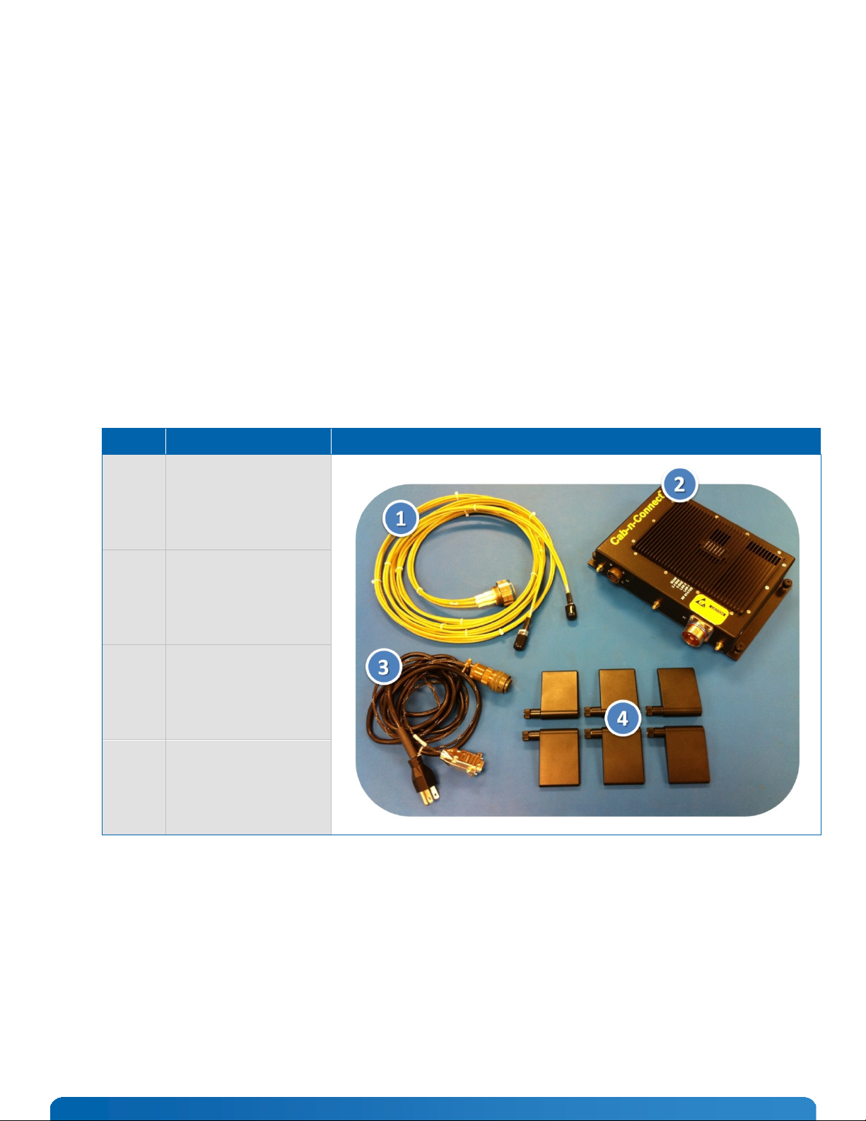
4.1 CWAP Equipment ............................................................................................................................ 7
4.2 Power Up and Log In ....................................................................................................................... 8
4.3 Connecting using the Console Port ................................................................................................. 8
4.3.1 Reset CWAP to factory default settings............................................................................... 9
4.4 Web-based GUI ............................................................................................................................. 10
4.4.1 Connecting using the WAN Port ........................................................................................ 10
ii
4.4.2 Connecting using the LAN Port ......................................................................................... 10
4.5 GUI Login Screen .......................................................................................................................... 10
4.6 GUI Quick Setup Configuration ..................................................................................................... 11
4.6.1 System Configuration......................................................................................................... 11
4.7 Flag Antennas and Bracket Assembly Installation ........................................................................ 13
5Support and Service........................................................................ 14
5.1 Technical Support .......................................................................................................................... 14
5.2 Returning Defective Merchandise.................................................................................................. 14
6Appendix A: List of Figures ............................................................. 15
7Appendix B: List of Tables............................................................... 16
8Appendix C: Document Revision History......................................... 17
1
1 User Information
1.1 About This Document
This document provides information about products from Kontron and/or its subsidiaries. No warranty of suitability,
purpose, or fitness is implied. While every attempt has been made to ensure that the information in this document is
accurate, the information contained within is supplied “as-is” and is subject to change without notice.
1.2 Copyright Notice
Copyright © 2012 Kontron. All rights reserved. No part of this document may be reproduced, transmitted, transcribed,
stored in a retrieval system, or translated into any language or computer language, in any form or by any means
(electronic, mechanical, photocopying, recording, or otherwise), without the express written permission of Kontron.
1.3 Trademark Notice
This document many include names, company logos and trademarks, which are registered trademarks and, therefore,
proprietary to their respective owners.
1.4 Standards
Standard
Description
ARINC 763-3
Network Server System
D6-36440
Boeing Standard Cabin Systems Requirement Document FED-STD-595 Colors Used in
Federal Procurement
IEEE 802.11a
Wireless LAN Media Access Control (MAC) and Physical Layer (PHY) Specifications –
High-speed Physical Layer in the 5 GHz Band.
IEEE 802.11b
Physical and Media Access Control (MAC) layer definition for ISO 7 stack
communications devices.
IEEE 802.11g
IEEE Standard for Information Technology - Telecommunications and Information
Exchange Between Systems - Local and Metropolitan Area Networks - Specific
Requirements - Part 11: Wireless LAN Media Access Control (MAC) and Physical Layer
(PHY) Specifications: Further Higher Data Rate Extension in the 2.4 GHz Band.
IEEE 802.11n
IEEE Standard for Information Technology - Telecommunications and information
exchange between systems-Local and metropolitan area networks-Specific requirements-
Part 11: Wireless LAN Medium Access Control (MAC) and Physical Layer (PHY)
specifications. IEEE 802.1x Port-Based Network Access Control
IEEE 802.3
Information Exchange Between Systems—Local and Metropolitan Area Networks—
Specific Requirements—Part 3: Carrier Sense Multiple Access With Collision Detection
(CSMA/CD) Access Method and Physical Layer Specifications. RTCA/DO-254 Design
Assurance Guidance For Airborne Electronic Hardware
RTCA/DO-160F
Environmental Conditions and Test Procedures For Airborne Equipment RTCA/DO-178B
Software Considerations in Airborne Systems and Equipment
FAR-25.853a Cert
Federal Aviation Regulations for Flammability ISO 9001/2008 International Organization
for Standardization, Quality Management ANSI/IPC-A-620 Acceptability of Electronic
Assemblies ANSI/J-STD-002 Solderability Tests for Component Leads MIL-C-5542
Chemical Conversion Coatings on Aluminum and Aluminum Alloys
2
1.5 Warranty
This Kontron product is warranted against defects in material and workmanship for the warranty period from the date
of shipment. During the warranty period, Kontron will at its discretion decide to repair or replace defective products.
Within the warranty period, the repair of products is free of charge as long as warranty conditions are observed.
The warranty does not apply to defects resulting from improper or inadequate maintenance or handling by the buyer,
unauthorized modification or misuse, operation outside of the product’s environmental specifications or improper
installation or maintenance.
Kontron will not be responsible for any defects or damages to other products not supplied by Kontron that are caused
by a faulty Kontron product.
1.6 Referenced Documents
Kontron Document # 73001000-FAT, Factory Acceptance Test Procedure, CWAP
Kontron Document # 73001000-CMM Component Maintenance Manual (CMM), CWAP
Kontron Document # 73001000-ESS Environmental Stress Screen Procedure, CWAP
Kontron Document # 730010000-FMEA, Rev A, CWAP
Motorola AP-7131 Series Access Point Product Reference Guide
1.7 Technical Support
Technicians and engineers from Kontron and/or its subsidiaries are available for technical support. We are committed
to making our product easy to use and will help you use our products in your systems.
Please consult our Web site at http://www.kontron.com/support for the latest product documentation, utilities, drivers
and support contacts.
1.8 Important Instructions
The following general instructions should always be followed in order to assure the proper operation of the COBALT
unit, the safety of operators and the preservation of warranty coverage.
Warning!
All precautions, procedures, and safeguards to prevent damage due to ESD,
and promote the safe handling of electronic components must be followed.
It is assumed that a competent technician familiar with electro-mechanical assemblies will be performing any testing
or troubleshooting of the unit. For detailed interconnection of power and signal wiring refer to the sections on
Physical I/O and Starting Up.
3
IMPORTANT: Avoid removing any identification plates, serial numbers or warning labels unless specifically
authorized by the manufacturer.
1.9 Exclusion of liability notice
Exemption from Liability for Accidents
Should the user disregard the instructions (specifically the safety instructions) in this manual and possibly on the
device, Kontron will be exempt from legal liability for accidents.
Limitation of Liability / Warranty Obligations
In the event of damage to the device, which is caused by a failure to observe the instructions (specifically the safety
instructions) in this manual and possibly on the device, Kontron will not be required to honor the warranty, including
during the warranty period, and will be exempt from legal liability for accidents.
4
2 Safety instructions
2.1 Electrostatic Discharge (ESD)
Electronic boards and their components are sensitive to static electricity. Therefore, care must be taken
during all handling operations and inspections of this product, in order to ensure product integrity at all
times. Do not handle this product out of its protective enclosure while it is not used for operational
purposes unless it is otherwise protected.
A sudden electrostatic discharge can destroy sensitive components. Proper packaging and grounding
rules must be observed. Always take the following precautions.
1. Transport boards and cards in electrostatically secure containers or bags.
2. Keep electrostatically sensitive components in their containers, until they arrive at an electrostatically
protected workplace.
3. Only touch electrostatically sensitive components when you are properly earthed.
4. Store electrostatically sensitive components in protective packaging or on anti-static mats.
2.2 Precautions for Installing the System
Important Instructions!
Please follow the corresponding instructions in this manual when installing/mounting the CWAP platform.
Please observe all specified dimensions required for mounting included in the drawing with outline
dimensions
When installing the CWAP, there must be at least 40 mm (approximately 1.575") free space around the
cooling fins to prevent the system overheating.
Leave approximately 4.0” (100 mm) of free space to the front and rear of the unit in order to have access
to the connector interfaces to properly connect the peripherals.
The cooling fins of the chassis must not be obstructed.
The platform must be firmly attached to a clean flat and solid mounting surface. Use proper fastening
materials suitable for the mounting surface. Ensure that the mounting surface type and the used mounting
solution safely support the load of the cobalt and the attached components.
Follow the local/national regulations for grounding. A ground bonding measurement (between CWAP
chassis ground and the mounting surface) should be conducted to ensure proper safety and EMI
characteristics are maintained.
The voltage feeds must not be overloaded. Adjust the cabling and the external overcharge protection to
correspond with the electrical data indicated on the type label.
5
3 Introduction
3.1 Product Description
The Cabin Wireless Access Point (CWAP) is a network distribution system designed specifically for
commercial airborne applications. The CWAP complies with IEEE 802.11a/b/g/n wireless standards
utilizing a Commercial-Off-The-Shelf (COTS) wireless access point in the appropriately assigned radio
frequency spectrum to facilitate wireless communications to other personal and aircraft devices. The
CWAP provides a bridge between IEEE 802.3 wired Ethernet LANs and IEEE 802.11a/b/g/n compliant
wireless networks.
The CWAP is provided with aircraft level discrete inputs and outputs to facilitate event notification and
equipment status to and from other aircraft systems, including remote control ON/OFF. The product is
equipped with an avionics wide frequency (360-800Hz) power supply unit with a 200msec holdup
capability for power interruptions. The CWAP requires no active cooling system, and has capabilities for
built-in diagnostics reporting. The CWAP is designed to comply with the general requirements identified
in Section 8 (Cabin Wireless LAN Unit) of the ARINC 763-3 Specification. The unit communicates to a
host server by physical connection over wired 10/100/1000Base-T interfaces.
3.2 Functional Block Diagram
Figure 1 contains an overview of the CWAP functional structure and interfaces
Figure 1 - Functional Block Diagram
Block ID
Functional Block
Description
1
Signal Interface Board
(SIB)
Provides the interface for the four discrete external I/O signals; 115Vac, and
RS232 signals. Also includes under temperature turn-off circuitry.
2
Power Supply (PSU)
Converts 115Vac input power to the proper DC voltages required by the I/O
and Radio Boards. Provides power supply and radio power status to the I/O
Board.
3
Radio Board
Provides the access point interface between the 2.4 and 5 GHz antenna
interfaces,
Table 1 - Functional Block Diagram Table
6
3.3 Equipment Definition
The CWAP leverages state-of-the-art COTS hardware to establish a rugged, versatile, high performance
wireless network access product. The minimal overall size and weight facilitates a variety of installation
options. Figure 1 depicts the general block diagram of the unit.
The standard features of the CWAP include:
COTS architecture based on 802.11a/b/g/n standards for wireless communications
Discrete inputs to control remote On/Off and RF Enable/Disable
Discrete Outputs for RF Status and Power Supply Status
Internal (AC/DC) power with interruption holdup capability
Dual Ethernet 10/100/1000BaseT ports interface to Airborne Network Server Unit and/or
additional CWAP
Lightweight and compact electro-mechanical packaging
Mil Circular connector for signal/power interfaces
Mil Circular connector with Quadrax inserts for Ethernet interfaces
Six (6) RF SMA-RP coaxial connectors for remote antenna attachment
3.4 Major Hardware Components
The CWAP major hardware assemblies are:
COTS Wireless Access Point Assembly
Power Supply Unit (PSU) with build-in hold-up (200msec)
Signal Interface Board (SIB) circuit card assembly for aircraft discrete input/output
Status Indicators, LEDs
External connection points for power and I/O, Ethernet, and external antenna
3.5 CWAP Orderable Part Numbers
Model Number
Description
73001000-001
LRU, CWAP ASSY, (INTL VERSION)
73001000-002
LRU, CWAP ASSY, (US VERSION)
73001001-001
LRU, KIT, FLAG ANTENNAS, CWAP
5007120-1
KIT, EXTERNAL CWAP CABLES
Table 2 - CWAP Orderable Part Numbers
7
4 Starting Up
The CWAP system is ready to use out-of-the-box. Evaluation units come with a complete interface cable
set as shown in the following table. For production units, cable harness assemblies can be ordered
separately. If you are building your own cable harness, see Section 5 for signal pin out and mating
connector information.
The CWAP is a conduction cooled system and requires no additional fan assist if operated in the defined
environmental conditions. Note that the unit may get warm and/or hot to the touch and should be handled
with caution during use.
Note, there is a temperature sensor that prevents the CWAP from turning on below -20ºC (+/-2ºC).
4.1 CWAP Equipment
Label
Description
Equipment
1
Cable Assembly with 2x
GbE RJ45 connectors
PN: 5006862-1
2
CWAP
PN: 73001000-00x
3
Cable Assembly with AC
3-prong power plug and
DB-9 console connector.
PN: 5006863-1
4
Flag Antennas (6), bracket
not shown.
PN: 73001001-001
Table 3 - CWAP Equipment