KooIR WineKoolR 250 User manual

ASSEMBLY &OPERATION MANUAL
250 500
WineKoolRTM

LOCATING YOUR WINE CELLAR
Provide 2 1/2
Never locate your wine cellar outdoors or in an area with extremes of temperature and humidity. These units
humid (above 50%R.H.).
Outlet power must be a DEDICATED separately fused, grounded, 15 Amp 110 - 120 V line or 7.5 Amp - for 240 V
models (CHECK BOX OR SERIAL NUMBER LABEL ON UNIT FOR YOUR LINE VOLTAGE REQUIREMENTS).
KoolR Products will not be liable or responsible for incidental or consequential damages. (See Warranty).
Place unit in a clean area and allow access to the exterior surfaces for periodic vacuuming of the condenser coil.
(See troubleshooting for details.)
Clean using a damp cloth and no detergents or polishes under any circumstances.
Always remove all bottles before relocating your wine cellar.
AREA FOR ASSEMBLING YOUR WINE CELLAR
TOOLS
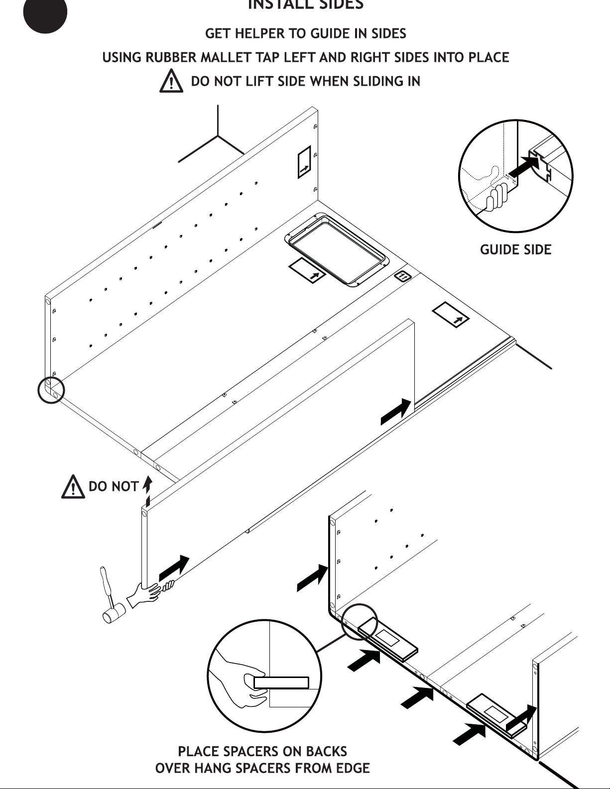
Rubber mallet, hex wrench (included), phillips screwdriver.
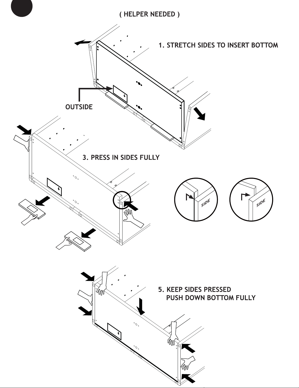
Helper is needed.
TEST THE COOLING UNIT
Plug it in on a table top, to verify that controls and display are functional, and that the unit is producing cool air
after a few minutes of operation.
Note that the electronic controller has a one-minute safety delay between initial plug-in and start-up of the
compressor.
BEFORE YOU START !
of the unit or on the light cord.
READ THE "USE AND CARE GUIDE" BEFORE YOU START
TM

x 1
x 1
B
Legs
x 6
A
Hinge Washer
x 2
Shelves
x 26
TOP
LEFT
REAR
TOP
RIGHT
REAR
x 1
x 1 x 1
x 2
SPACER
Spacer
x 2
CONNECTOR PLATES
x 2 x 2
HINGES VENT
HARDWARE
Brace
x 4
x 2
C
Cooling Unit Bolts
in cooling unit box
D
Allen
in cooling unit box
x 1
E
Hooks
x 2 Wrench
x 1
Handle and Lock
x 2
FG
x 1
Power supply
Wall Ties x 2
J
Anchors x 2
Model 250 only !
G
Screws x 2
HI

INSERT CORNER (LEFT ONLY)
1
BACK
PLACE AGAINST WALL
FLOOR
WALL
BACK
BACK
PLACE AGAINST WALL
BACK
POST 1
FLOOR
WALL
FLOOR
WALL
TIP

2
INSERT
FLOOR
BACK
PLACE AGAINST WALL
BACK
RIGHT
BACK
RIGHT
WALL
BACK
POST 1
RIGHT CORNER
FLOOR
BACK
RIGHT
WALL
BACK
RIGHT

BACK
PLACE AGAINST WALL
LEFT
BACK
RIGHT
LEFT
RIGHT
WALL
SPACER SPACER
LEVEL
PUSH OR TAP
AT BOTTOM
TO TAB
SPACER
LIFT
3

BACK
PLACE AGAINST WALL
BOTTOM
OUTSIDE BACK
4
INSTALL
BOTTOM
2. REST BOTTOM ON SPACERS
OK
NO
SPACER SPACER
BOTTOM
OUTSIDE BACK
BAC
PLACE AGAINST WAL
4. PULL OUT
SPACERS
BOTTOM
BOTTOM
BA
PLACE AGAIN
BOTTOM
OUTSIDE BACK
BOTTOM
PRESS
PRESS
P
RE
PRESS

5
HAND PRESS IN ALL CONNECTOR PLATES IN BOTTOM
TAP IN CONNECTORS TIGHTLY (NO GAP) WITH CLOSED HAND OR RUBBER MALLET
SCREW IN ALL LEGS
INSTALL
BOTTOM
CONNECTOR
PLATES
B
LEAVE 1/4” SPACING ON CORNER LEGS
1/4” SPACING ON 4 CORNERS (Easy access in upright position for final leveling.)
LEAVE 1/2” SPACING ON CENTER LEGS
1/2” SPACING ON CENTERS (Limited access in upright position.)
WARNING! Connector plates can be removed ONLY as described on page 19.
BOTTOM
OUTSIDE BACK
BOTTOM
A
BOTTOM
LEFT
REAR
TAP
GENTLY
BOTTOM
RIGHT
REAR
HINGE 1
HINGE 2
CENTER
REAR
BOTTOM
CENTER
FRONT
B
LEGS
WASHER
A
WASHER
NO GAP!

TOP
INSTALL
TOP
A: INSERT TOP VENT
CHECK ORIENTATION
VENT
OUTSIDE
PRESS FOR
FIRM LOCK
(OPPOSITE SIDE)
6

INSTALL
TOP
BA
PLACE AGAINS
TOP
OUTSIDE
BACK
TOP
REPEAT STEP ON PAGE 7 FOR TOP
4
6
DO NOT INSTALL HINGES YET!
INSTALL TOP CONNECTOR PLATES
TOP
OUTSIDE
BACK
TOP
RIGHT
REAR
TAP
GENTLY
TOP
LEFT
REAR
CENTER
REAR
TOP
PRESS
PRESS
NO HINGE
NO HINGE
PRESS
PRESS
B:
WARNING! HINGES can be removed ONLY as described on page 19.

7INSTALL
CENTER
POSTS
2
4
3
TOP
SLOTS

8
HINGE 2
TOP
ON BOTTOM
HINGES ONLY
HINGE 1
TAP
GENTLY
WASHER A
PLACE WASHERS FIRST
INSTALL TOP HINGES
Door is made of very tough PLEXIGLAS, but it can be scratched. Handle and clean with care!
NOTE: DOOR GASKET WILL RELAX IN A FEW DAYS ASSURING A GOOD SEAL

9
!
!
"
"
CELLAR BOTTOM
INSTALL
BRACES
5
AND
6
(HELPER NEEDED TO HOLD CABINET STEADY)
"
TABS
ALIGN TO TABS, PUSH DOWN BRACES 5 (× 2)
AND 6 RU(× 2)

PRESS
CELLAR BOTTOM
10 INSTALL
SHELVES
TAB REFERENCE
START AT MIDDLE
PRESS IN SIDES
CLICK SHELF
OVER TABS
LONGER
SHORTER
FRONT
SHELF
TAB
PRESS

11 PLACE
COOLING
UNIT
IN
CABINET
C
IN COOLING
UNIT BOX.
CLEAR OPENING
STRAIGHTEN AND
PUSH THROUGH
GET HELPER TO
PULL FROM INSIDE
AND LIFT UNIT
LEVEL DURING
FASTENING
LEVEL TO
OPENING
UP
TIGHT!
CHECK AFTER TIGHTENING !!!
VENT
COOLING UNIT MUST SEAL !

1
12
13
Wine
List
2
3
1. Connect the power to
the power supply(F)
2.
Stick the power supply
to the top panel
3. Connect the low voltage
plug to the voltage
DOWN (Hinge on Left)
UP (Hinge on Right)
Door latch:

14 LEVEL
CELLAR
LEVEL DOORS
ADJUST OUTER LEGS TO LEVEL DOORS
D
UP
G
HINGES ARE PRE-SET
ADJUSTMENTS SHOULD NOT BE REQUIRED

WALL
GG
H
I
DRILL USING 1/4” (6 - 6.5 mm) DRILL BIT AND TAP IN ANCHORS
PRESS IN FULLY WALL TIES INTO REAR CONNECTOR PLATES AND SCREW IN SCREWS
H
I
BRACE TO WALL - for 250 models ONLY
WALL MATERIALS VARY, USE APPROPRIATE ANCHORS FOR YOUR APPLICATION.
15
TO AVOID INJURY OR DAMAGE ALWAYS BRACE TO WALL !
RISK OF INJURY !
IF CABINET IS NOT FULLY LOADED IN THE BOTTOM IT CAN BE TOP HEAVY.
DO NOT
PRESS IN FULLY !
NEVER MOVE LOADED CABINET!
EMPTY FIRST!

TIGHTEN LEGS
FULLY
PRY OFF
CONNECTOR PLATE
REUSE LEG
FOR
TOP HINGE
REMOVE COOLING UNIT AND SHELVES
LAY CELLAR DOWN
FULLY TIGHTEN LEGS
PRY OFF ALL CONNECTOR PLATES WITH FLAT SCREWDRIVER
!"##"$
"%#&'()
!*+,
AND CENTER REAR

Calibration option of the temperature sensor.
Display of actual temperature by request.
Digital temperature sensor.
Settings are stored in memory for power failures.
delay of 1 minute the fan will start, followed by the
compressor within the next minute.
The unit will cycle ON/OFF based on the temperature reading. Fan speeds are automatically set by the controller to achieve optimum
performance.
Minimum ON and OFF cycle times are imposed by software, to prevent "short cycling".
alternating with the temperature reading.
- Unplug and re plug the unit after 10 minutes.
57 56
70 57
57 57
57 58
57 56
57 14
57 57
57 F0
F0 F1
F0 -1
Actual temperature: PRESS
SET temperature: PRESS
PRESS and RELEASE
To increase: PRESS once per degree
To decrease: PRESS once per degree
The new value will be memorized and the controller will reset automatically.
Wait 5 seconds
USE for each degree of positive offset
for each degree of negative offset
BEFORE AFTER
TEMPERATURE
(range is 53-64
TO CHANGE FROM
CONTROLLER
OPERATION ACTION
A negative offset will result in a warmer cabinet and a positive offset will result in a cooler cabinet.
The new value will be memorized and the controller will reset automatically.
(wait
one
minute)
KEYS
+
-
This manual suits for next models
1
Table of contents
Popular Kitchen Appliance manuals by other brands

TEFAL
TEFAL P6060432 user guide

Fisher & Paykel
Fisher & Paykel Elba OR61 Series Installation instructions & user guide

PowerXL
PowerXL TO6030-1SP Use & care manual

Brentwood Appliances
Brentwood Appliances GA-301BK Operating and safety instructions

Brentwood Appliances
Brentwood Appliances PC-482 SOCCER Operating and safety instructions

Uncanny Brands
Uncanny Brands MILWAUKEE BUCKS MW1-NBA-BUK-MAS Operating and safety instructions