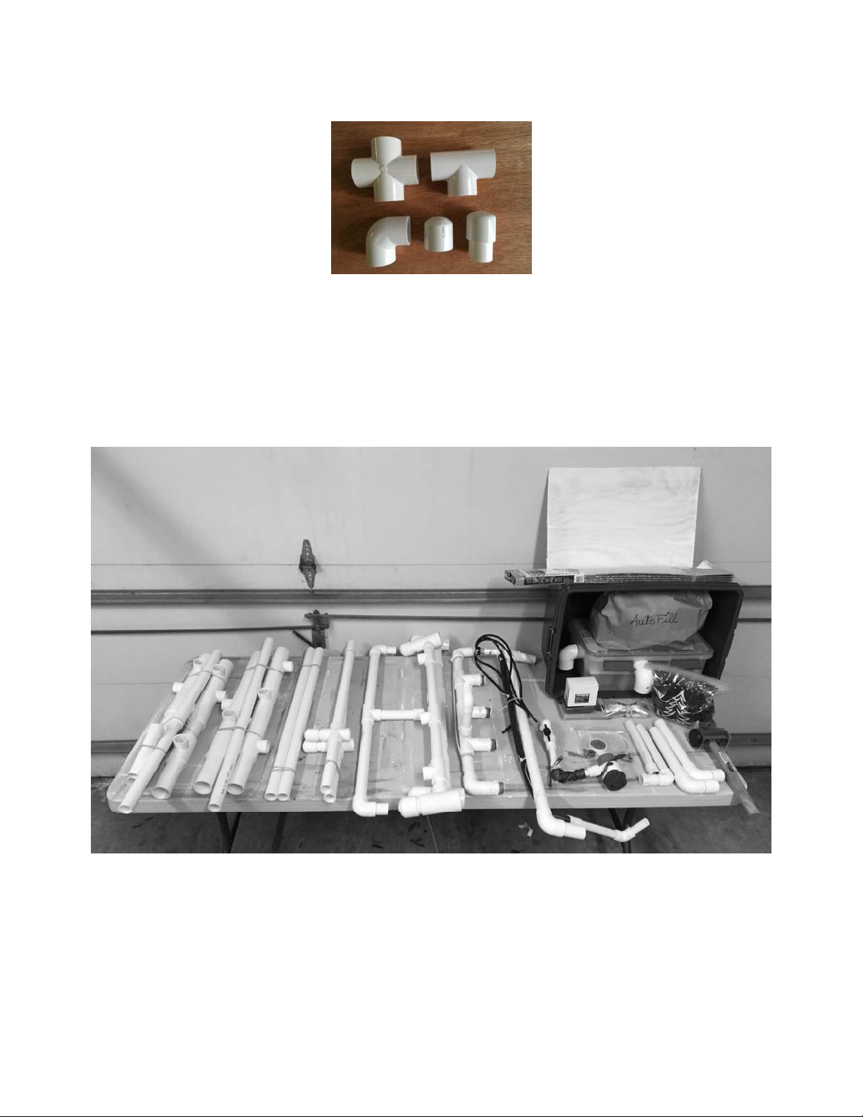
Kool Sci My Garden User manual

1
ASSEMBLY
OUTDOOR SOLAR GARDEN
IMPORTANT
• Legs now include solar anel su orts on 3 sides (E, S, & W)
• DO NOT ROTATE LEG TEES OR YOU MAY NEVER REPOSITION THEM AGAIN!
• With 2 exce tions gluing i es and fittings is neither recommended nor needed. Not gluing
allows for adjustments during assembly and for easy disassembly for moving and storage.
Loose connections can often be tightened using Teflon ta e (included)
• The Garden is described with ends (N&S) and sides (E&W). This is im ortant from a
horticultural stand oint because the N end receives no direct sun, the E side receives the
excellent morning sun, and the S end and W side receive the hot direct afternoon and
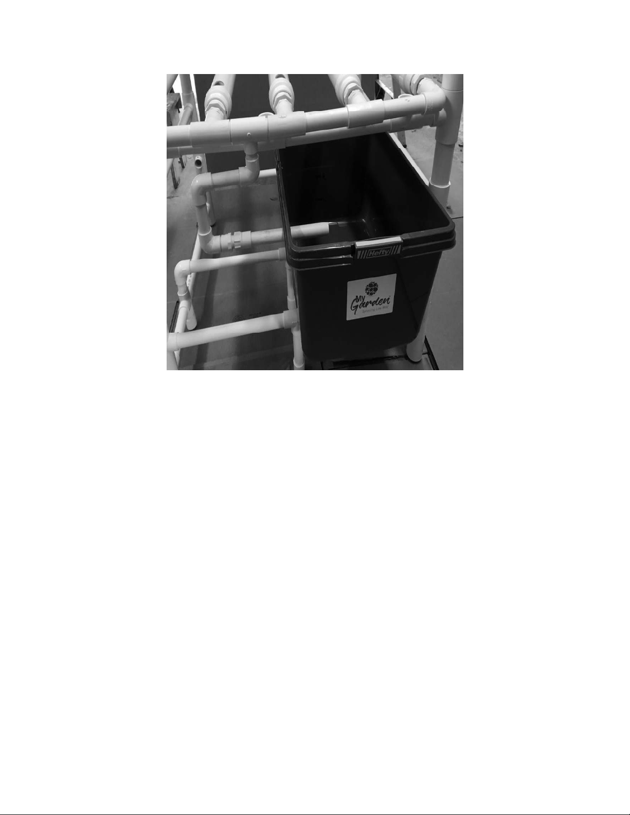
evening sun. The Garden’s functional com onents – reservoir and electrical box – are
located at the N end and Garden ex ansion occurs linearly to the S end.
• Use QPlugs only, NEVER use soil or loose growing media with the Garden. The small-bore
s aghetti tubing will clog.
• Kee the Electrical box closed and sealed. There’s lots of water around the Garden that’s
incom atible with electrical equi ment and connections
• Flat surfaces e.g. atios, decks, driveways make life easier but with shims, a level, and
atience the Garden can be situated almost anywhere. Proximity to a hose bib is a lus,
see Autofill below
• Solar means for sun required for both lants and PV anels. Both need almost full sun to
exceed ex ectations. Morning sun is most im ortant. MyGarden will disa oint in shady
locations.

2
Figure 1. Clockwise from the cross: tee, lug, ca , and elbow
Lift out the i es and i e bundles and se arate them carefully on a large table or clean floor
Figure 2. Left to right: N end bundle, S end bundle, to side bars, bottom side bars (note crosses), Reservoir su ort bar, (2) To
Bars, Manifold, and Irrigation system attached to its su ort bar. Outside and in front of the reservoir is the um and combination
flow valve control / filter system, small bag of su orting items, the return to reservoir drain i es, solar anel su orts (2 of 6
shown), rubber mallet and GroPlugs (behind mallet). Inside reservoir is the electrical box (bottom), Autofill (above), lant
nutrients and battery charger (immediately in front). Above the reservoir is the reservoir su ort shelf and a solar reflector to
rotect both the electrical box and the reservoir from the sun.

3
STRUCTURE
Begin assembly with the leg bundles (figure 3). Note the ca s at the ends of some of the i es (far
right). They are “feet” that end u on the ground when the Garden is u right. The S end bundle
has a straight bottom bar while the N bottom bar includes a short middle leg that will su ort the
Reservoir.
Figure 3. Leg bundles: S end to , N end bottom of icture
O en the S end bundle and insert the S end bottom bar into the 2
nd
from the bottom tees on both
legs. Note that there are lots of tees making u each leg. Do not twist them! Put aside the S end.
Figure 4. This makes the S end once the straight bar is inserted into the lowest tees on each leg

4
O en the N end bundle and note that the N end bottom bar includes a short central Reservoir
su ort leg. Insert the short su ort leg into its tee and insert the N end bottom bar into the 2
nd
from the bottom tees on the N legs. This makes u the N end.
Figure 5. This makes the N end once the bottom bar and reservoir su ort is inserted into 2
nd
from the bottom tees on each leg
Locate the side bottom bars, the only com onents made with crosses.
Figure 6. side bottom bars. As always, the feet (ca s) go down
Lay the S end flat on the ground. Insert the longer of the 2-side bottom bar i e segments into the
lowermost S end leg tees. The side to bars are straight i es. Insert them into the to tees on the
S end legs. Study figure 7. You Garden should look like this at this oint.

5
figure 7 showing the to and bottom side bars inserted into the S end legs. Looking to down from the N end
Now lay the N end over to and match u the leg tees with i e ends as shown in Figure 8.
Figure 8 showing the N end (to ) overlaid onto the 4 side i es coming from the S end (on the ground)

6
Once all i es are in their fittings ush down gently on all connections. Roll the Garden onto each
of its four sides re eating the rocedure. Then stand the Garden on its feet.
Locate the to bars identified by large 1 ½” tees at each end with 3 small 1” tees along their
horizontal axis’. Identical to bars go ato both the N and S ends and locking down the structure.
To bars have two horizontal i e sections: 12 ½ and 8 ½ inches. When standing in front of the N
end looking towards the S end the longer 12 ½” section goes to your right.
Figure 9. To bars, identical com onents ato both the N and S ends
Figure 10. The Garden structure on its feet with the identical N and S to bars attached. Notice that the longer i e segment on the
to bars goes to the right when looking from N end to S end as shown above.
Next insert the central reservoir su ort bar into the crosses on the side bottom bars.

7
Figure 11. Inserting the central reservoir su ort bar com letes assembly of the main structure
To fully insert i es into fittings firmly ress down on each corner once more re eating the
rocedure while rotating the structure.
Plant su ort bars are o tional and can be re laced with lugs when lants are small. The bars
server two ur oses. They su ort taller, bearing lants that often tend fall over, and they’re
easily substituted for bottle su ort i es if a gardener chooses to grow larger lants in 2-liter
bottles (another o tional method of roduction in MyGarden).
Figure 12 showing lant su ort bars often re laced with the lugs when cro s are small. The small holes in the long horizontal
i es (not shown in the i es above) are for bottle su ort stra s if the o tion for a GroBottle o tion is selected.
Locate the manifold illustrated u side down in Figure 13 below. Make certain the 5 orts are
erfectly lined u , stand the manifold vertically on a concrete surface, and ush down firmly to
make sure all fittings are firmly seated. The manifold sits ato the N end to bar, held in lace by
the five GroPi es that screw into the manifold orts. Hold it in lace now by screwing in one
Reservoir Su ort Bar

8
GroPi e. The return to reservoir section ( ointing u here but down during o eration) is glued
together exce t for its connection with the manifold. That connection is made with Teflon ta e to
allow for fine tuning adjustments during assembly. If it dri s during testing add additional ta e.
PLUMBING
Figure 13 the drain manifold and return to reservoir section (shown here u side down). The 5 manifold orts oint to the S end to
acce t the GroPi es, and the return to reserve sits below underneath ointing towards the reservoir (see Figure 14)
Figure 14 view from N end to S end illustrating how one threaded GroPi e su orts the manifold in lace above the N to bar. Note
return to reservoir section below the to bar

9
Figure 15 is a view from the S end looking towards the N end and the manifold held in lace using one threaded GroPi e. Note
return to reservoir section below the to bar
Figure 16: The 5 GroPi es installed on the manifold

10
Figure 17 illustrating the return to reservoir manifold section connected to the reservoir via a removable return to reserve i e. A
2
nd
90
0
return to bucket i e (not shown) is included to use when draining the reservoir into a bucket during nutrient solution
change out (Hint: fertilize otted lants and flowers with used nutrient solution).
Locate and install the irrigation system (Figure 18). Com onents include the su ort bar
(horizontal PVC), connection system to the um and filter system inside the reservoir (vertical
section), irrigation tube (1/2” rubber tube), nutrient solution manifold, and five s aghetti
distribution tubes, one to each GroPi e. Everything is reassembled. Insert the irrigation su ort
bar’s vertical i es into the middle tees on N and S end’s to bars. The irrigation manifold goes to
the S end. The vertical connection system to the reservoir is flexible and swivels to assure easy
access into the Reservoir through a small 1” hole. The short rubber tube section is glued into the
white lastic connector but is not glued with the grey lastic 90
0
connecting elbow. If you find a
leak here, sim ly tighten the small i e clam .

11
Figure 18 Irrigation system. Note the vertical section that dro s down and enters the reservoir, connecting to the um and filter
system inside the reservoir through a small 1” hole.
Free the s aghetti tubes and stick one down into the small holes at the end of each GroPi e.
CAUTION: Do not loosen the cable ties holding the ½” rubber irrigation tube on its PVC su ort
bar!

12
Figure 19 is how your assembly should look at this oint. Move the s aghetti tubes into the small Gro i e holes. These GroPi es
and the irrigation system are shown ready to cou le with same on an Add On Unit (an o tion not shown). The em ty to bar tees
should hold either the lant su ort bars or lugs to kee rainwater out of the structure (you can install the lant su ort bars
later when your lants require su ort).
THE RESERVOIR & AUTOFILL
Two o tions often ordered with the Outdoor MyGarden are Autofill, which automatically
re lenishes the water in the reservoir either once or twice er day, and Add On Units (AOU),
which set u easily and double and tri le MyGarden roduction for little additional cost.
Autofill is not necessary to start out and when the Garden is used to germinate small seedlings for
trans lanting, when growing miniature vegetables, or under artificial lights. Autofill is almost
essential, however, when growing larger cro s es ecially in hot sunny weather when you’re not
available to add water to the reservoir manually once or twice a day. Because Autofill is so
im ortant all reservoirs for Outdoor Gardens shi with the Autofill Level Control Valve installed.
The Valve is reset to the 8-gallon mark (the to of the float at 6 ¾”). Adding the Autofill o tion
later is very easy. See below for more Autofill information.

13
Put the su ort board on its su ort i es (Figure 20) and lace the reservoir on the board all the
way to the West (right) with sidewall holes to the left (Figure 17 above). Center the Level Control
Valve stem inside the 3” circle cutout in the board. The reservoir extends beyond the N End for
easy access when you need to change out the nutrient solution, clean the filter, re lace the um ,
or adjust the Level Control Valve.
The Level Control Valve can be damaged in shi ing and this is the best time to test it for leaks.
Leaks cannot be tolerated because, although water is easily re laced es ecially with Autofill, lost
nutrients are not re laced until the next nutrient solution change out. Place a a er under the
base of the Valve and ut 4 gallons of water in the reservoir to check for leaks. If you see no dri s,
you’re good, continue with assembly. If the Valve does dri (rare) turn it over and carefully
tighten the large white nut. If dri ing ersists (very rare) you’ll have to unscrew it and add more
ro e utty (included) to its base before re lacing and tightening the nut.
Figure 20. Note the correct ositioning of the reservoir su ort board at the N end of the Garden. The 3” diameter
circle holds the base of the Autofill Level Control Valve.
Download a se arate short document for Autofill installation details

14
ELECTRICAL
Place the electrical box next to the reservoir on the reservoir su ort bars (Figure 21).
Figure 21. Correct Reservoir ositioning. Note the 2 holes in the reservoir wall, the smaller and larger accommodate res ectively
the vertical section of the irrigation system and the return to Reservoir i e. The level control valve (inside Reservoir) shi s
installed in every Reservoir. The silver connector below the Reservoir is art of the o tional AutoFill. Reservoir su ort board not
shown.

15
Figure 22 the electrical box situates adjacent to the reservoir. Note the manifold return to reservoir system above the box.

16
Figure 23 showing the um and filter assembly with wires exiting to the adjacent electrical box. Newer Reservoirs lack the wire
slit in the u er rim and the wires ass through the same hole as the vertical valve / filter irrigation assembly. Pum ositioning
and attachment methods vary.
The most current assembly and o erations instructions and suggestions are always
available at
www.KoolSci.org

17
Figure 24 Electrical box. Contents include battery (12v, 7ahr); Genasun solar charge controller; rogrammable timer (instructions
beneath); battery charger; and battery tester (green). Solar anel in uts enter through the elbow on the left and mate with the
connectors at “solar anels in”. Pum wires enter through the elbow at bottom of icture and attach to the terminals labeled
“ um in”. Pum brown (+) and black (-) wires connect with circuit red (+) and blue (-) wires res ectively. Everything is easy to
reach es ecially the timer for rogramming. Lift the timer to access the single AA battery that we recommend changing between
cro s. The battery charger is for emergency charging only as in o eration the battery stays continually charged by the solar anels.
The battery tester is useful for measuring solar anel in ut as well as battery current.
The electrical box serves to connect the solar anels directly to the um , and to a charge
controller that kee s a small battery fully charged. We find it satisfactory for the timer to run the
um off the battery for 2 minutes at 10a, noon, 2 , 4 , and 6 . On sunny days the battery is
irrelevant as the anels ower the um . On rainy cloudy days, however, lants still trans ire
slowly and eventually wilt. A few minutes of battery charged um o eration throughout the day
is more than adequate to save those lants under those conditions. Don’t run the battery more
than necessary on cloudy days or you risk running it down. A battery tester is rovided. Set it to
12v to see how much juice is left in the battery. A battery charger is also rovided. If you find
your battery discharged remove it to a 120v source and let it charge overnight. Detailed
instructions including for rogramming the timer are included in the O erating Instructions. The
timer can be gently lifted to reach the battery com artment to re lace the 2 AA batteries

18
Each Garden comes with 6 solar anel su orts, 2 each for the E, S, and W sides. Almost always
kee a anel on the E side to catch the morning sun. The 2
nd
anel is usually best ositioned on
the S side but that de ends on time of year and osition of shade on your Garden s ot. Sometimes
an intermediate orientation is required e.g. SW. Panel wires are extra-long so you can osition
them anywhere around the Garden if it becomes necessary. Insert all 6 su orts but when a side is
not in use rotate the su orts in line with the Garden and out of the way. They rotate easily. Run
the anel wires through a hole in the a ro riate elbow on the electrical box and lug them in to
the wire leads connecting to “PV Panels – In” inside the box (see Figure 24). There is no on/off
switch for the anels, sim ly turn them over or cover them with cardboard when you must shut
them off e.g. for a minute during nutrient solution change out.
Although the Rule um is very reliable a breakdown can quickly ruin the garden. It is
recommended to kee a s are handy. The filter is a combination filter/ball valve. Nothing inside
the Reservoir is glued since small leaks there do no harm. Pull the ball valve a art frequently to
check and clean the screen inside. If the Reservoir is ke t closed there is seldom a filter roblem
after the first week of growing. The ball valve rovides some adjustment if/when needed. In most
cases on solar outdoors the valve is left wide o en.
Cut the autoshade reflective cover in half with scissors. Place half ato the closed Reservoir where
it effectively reduces solar heating of the nutrient solution (In Florida summers the solution has
been measured at 110 degrees way too hot for the roots of almost all cro s). Place the other half
on the Electrical Box to rotect the lastic. Without rotection one growing season in the sun can
destroy the lastic. A thorough, overla ing cover is essential to reserve the electrical box.
CONGRATULATIONS
You’ve assembled MyGarden. Add a cou le of gallons of water to the Reservoir and start u the
system to check for leaks and to rinse the system Leaks can occur in transit. Potential leak oints
include the Level Control Valve in the reservoir (tighten the white nut underneath) and the
Manifold Ports (turn the GroPi es another revolution to tighten the threaded connections. Even
tiny leaks can never be tolerated because they lose not only easily re laced water but also
nutrients!
Read the detailed O erating Instructions carefully for much more information
AUTOFILL
Check nutrient solution levels on a regular basis. During germination and early seedling growth
the level will dro very little. If necessary, add a small amount of water to return the level to the
fill line. If growing seedlings for trans lant Autofill won’t be necessary. If growing a full cro in
the Garden, however, one month after lanting you may be adding water daily. Once cro s are
roducing e.g. large tomato lants you may be adding significant quantities of water twice daily
(de ending on tem eratures and sunlight intensity). Large lants trans ire lots of water to kee
cool es ecially on hot, sunny days, making automatic watering a must.
There are 7 arts to AutoFill:
1. No-leak hose bib, the closer to the Garden the better (customer rovides)

19
2. O tional “Y” splitt r that accommodates the timer while leaving a bib ort available for other
uses;
3. Tim r that attaches to, and controls the water on and off at set times on one side of the splitt r;
4. Nutri nt solution l v l control valv already reinstalled in the Reservoir;
5. Solid r s rvoir support board
6. Conn cting ass mbly that connects the above level control valve to a garden hose;
7. Garden hose (customer rovides)
Autofill com onents from a building with a no-leak hose bib (left) to an outdoor MyGarden (right): hose bib (not
shown, customer res onsibility); s litter (allows Autofill to share the hose bib); timer (takes over the on/off function
from the hose bib; garden hose (not shown, customer res onsibility); level control valve (installed inside the
Reservoir)
The hose bib MUST BE leak-free because it will be ermanently o en with water flow controlled
by the Rainbird timer. Small leaks may be sto ed by wra ing Teflon ta e over the bib threads.
As a last resort re lace the bib.
Install batteries into the timer and rogram it er instructions. With medium leaf area setting the
timer to refill the reservoir once daily is adequate. Large leaf areas e.g. several giant tomato lants
growing over the Overhead Rack, you’ll need to re-u the reservoir twice daily. We suggest on for
2 minutes at a roximately noon and again at 4 . This becomes easy with ractice. And you
cannot overfill the reservoir because it’s the Level Control Valve in the reservoir that shuts off the
water even when the timer is on.
Screw the s litter onto the bib hand tighten only. Screw the timer onto one side of the s litter.
Now with the timer controlling on and off o en the bib handle about ¼ turn. Now under ressure
the hose bib / s litter / timer connections must not leak because they’ll stay ressurized
continuously 24/7. Note – leaks beyond the timer for exam le a rare hose burst are not roblems
because 1. The bib is only o ened a quarter turn, and 2. The timer will allow for flow for only
several minutes daily.

20
Thread the female end of the connecting assembly to the level control valve stem under the
Reservoir and the male end to the garden hose. The ends are not interchangeable as the i e
threads are different at each end. Screw the female end of the garden hose to the timer. Turn the
timer to the continuous on osition and adjust the level control valve until the water level is right
at the desired mark. Turn the timer back to the auto osition.
With Autofill installed and adjusted (a few minutes of adjusting the level control valve) sit back
and watch the Garden take care of itself. It’s a beautiful thing! More Autofill information available
in the O erating Instructions.
Check the website frequently for Assembly and O erating Instruction u dates and revisions as
well as for fun roject-based learning ideas!
control
The reservoir (su ort board not shown in this illustration) showing the two Autofill com onents best installed during initial setu
Note the connection between level control valve and connector, which is in turn connected to the customer’s garden hose. The
white nut indicated by the blue arrow must be tight. No leaking from the Reservoir ermitted or nutrients are lost.
Connector
Level control
valve
Level control
valve
White nut
Conn ctor
Popular Lawn And Garden Equipment manuals by other brands

FRAME IT ALL
FRAME IT ALL Stack & Extend VEGGIE WALL Assembly instructions

RioOutdoors
RioOutdoors 6P-WSC installation instructions

Craftsman
Craftsman 610.24600 User instructions

Miracle-Gro
Miracle-Gro AeroGarden Sprout LED Quick setup guide

Harbor Freight Tools
Harbor Freight Tools One Stop Gardens 92151 Assembly & operating instructions

DANA
DANA 4360-20 parts list