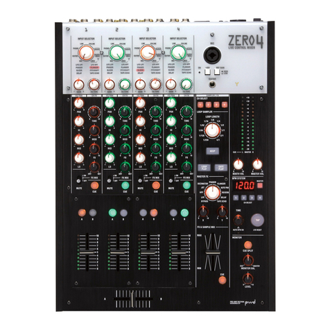
Korg Digital Mixer ZERO8 User manual


*MODE1[A,A]の場合、X-5810パネルエンコーダー用
SLOTはSCANしない


・
A
bout this check
A
fter repairing, you need not do all these checks.
P
lease do the necessary checks corresponding to the repairing.
W
hen you do the checks of Page1/14-Page5/14,
do the checks according to this manual.
P
age6/14-Page14/14 are checks for INPUTs and OUTPUTs.
T
hese do the checks that sound from INPUTs are correctly reproduced
from OUTPUTs.
Y
ou can use different equipments from this manual for these checks.
KORG INC.
No.
Date 1/12007.6.18
QCI-5810 Page
ZERO8 (X-5810) Check before Shipping
Revised

Equipments
:
・AC cord
・MIDI cable×1
・TRS standard (unbalance)--TRS standard (unbalance) cable x2
TRS standard (unbalance)--RCA Pin cable x2
・Headphones (both Standard plug and mini-plug)
・Audio analyzer or oscillator
・D3200 x1
1
.
Start of the Check
Appearance Check
(
Translation omitted.)
C
onnection
・
A
C cord
Connection
・
M
IDI cable(IN-OUT LOOP)
C
onnect the AC cord.
C
onnect MIDI IN and MIDI OUT as a loop.
How to start the Test Mode.
C
onfirm that the ZERO8 is factory setting (see end of this manual).
Pressing the [SEND] of ZERO FX section and the [HOLD],
t
urn the power on.
2. Internal Check
・
At first the Internal check starts in the test mode
.
(Fig1
)
・
SDRAM Check
①
Check of
SDRAM
②
When an error (Address bus or data bus) occurred,
the check stops and the segments (see right) are blinking
③
When the cheek has passed normally, the check proceeds to the next.
・
FlashROM Check
①
Manufacturer ID and Device ID are read from the Flash ROM.
②When an error occurred,
the check stops and the segments (see right) are blinking
③When the cheek has passed normally, the check proceeds to the next.
・
MIDI LOOP Check
①When an error occurred, the check stops and the segments (see right) are blinking
②When the cheek has passed normally, the
system version is displayed.
F
ig
1
Display of version
3
.
Confirmation of the system version
the system version is displayed.
C
onfirm that the system version is 1.04 or after.
*
Confirm that it is the newest version when some version-up has been done.
Press the
[MASTER]
to proceed to the next.
4
.
JACK SW Check
F
ig.2 is displayed in the LCD display.
F
ig
2
JACK SW Check
1.
Connect a cable to CH1 LINE INPUT (TRS) R terminal.
The LCD display changes like following.
JACK IN
'
LINE
2
CH
-
R
'
JACK SW
.
2
:
ON
2
.After confirmed the display, pull out the cable and connect
to the CH2 LINE INPUT(TRS) R.
The LCD display changes like following.
JACK IN
'
LINE
3
CH
-
R
'
F
ig
3
Until CH
8
,
try
JACK SW
.
3
:
ON
A
fter this, same as above, repeat to pull out the cable and connect it regarding following.
CH3-R, CH4-R, CH5-R, CH6-R, CH7-R, CH8-R
Fig.3 is displayed when the cable is connected to the CH8-R.
When the check passed normally, all LEDs of the ZERO8 are turned on.
P
ull out the cable from the
CH8-R
.
KORG INC.
*right photo
ZERO8 (X-5810) Check before Shipping
Revised
No.
Date 1/142007.4.25
QCI-5810 Page

5. SW & LED Check
All LED light 1
Fig 4
5-1. All LED light and individually light
F
ig.4 is displayed.
C
onfirm that each LED light by the color of "all LED light 1" in the Table1.
Press the
[
MASTER
]
.
F
ig.5 is displayed.
C
onfirm that each LED light by the color of "all LED light 2" in the Table1.
All LED light 2
Fig 5
Table1 LED light Check
LEDs which are checked. All LEDs light 1 All LEDs light 2
1-8CH GAIN Orange Red
1-8CH INPUT SELECTOR - EQ SELECTOR-HI-FREQ-MID-LO each volume Orange Blue
1-8CH PAN-EXT1-EXT2-ZERO FX SEND each volume Orange Blue
1-8CH [CUE][A][B] each switch Orange Blue
1-8CH FADER meter LED 0-8:Blue,9:Orange10:Red 0-8:Blue,9:Orange10:Red
Meter Back light L&R White White
Meter Peak LED L&R Red Red
FIREWIRE LED Yellow Yellow
EXT1 [CUE] EXT2 [CUE] ZERO FX [CUE] each switch Orange Orange
EXT1-EXT2-ZERO FX each volume Orange Orange
BOOTH-MASTER-(MONITOR section)BAL-LEVEL each volume Orange Orange
[SET UP]-[BPM]-[AUTO]-[TAP] each switch Blue Blue
(CONTROLLER BANK section)[A]-[B]-[C]-[D] each switch Blue Blue
1-8 each ROTARY ENCODER Blue Blue
[HOLD]-(ZERO FX section) CHANNEL]-[SEND]-[MASTER] each switch Orange Orange
A
fter the confirmation,
Individually light
p
ress the [MASTER]
Fig 6
F
ig.6 is displayed.
B
y each group "all LED light 1" and "all LED light 2" mutually light.
・
Ch
1
GAIN
・
CH
1
INPUT SELECTOR
,
EQ SELECTOR
,
HI
、
FREQ
,
MID
,
LO
each volume
・
CH
1
PAN
,
EXT1
,
EXT2
,
ZERO FX SEND
each volume
S
ame as above proceed the check , CH2, CH3,,,until CH8 by pressing the [MASTER].
After confirmed
CH8 PAN
,
EXT1
,
EXT2
,
ZERO
FX SEND
each volume, press the
[MASTER]
t
he meter LED beside the
CH FADER
begins to light.
C
onfirm that the meter LED lit from 0 to 10, and turned off from 10 to 0.
P
ress the
[MASTER]
.
T
he meter LED of CH2 begins to light.
S
ame as above, confirm CH3,,,CH8.
P
ress the
[MASTER]
to proceed to the next.
KORG INC.
2/142007.4.25
QCI-5810 Page
ZERO8 (X-5810) Check before Shipping
Revised
No.
Date

5-2. SW Check
Fig 7 SW Check
F
ig.7 is displayed in the LCD.
O
perate the switches like Table 2.
B:
Blue
R
:Red
Table2 SW Check
O:Orange
Switches which are checked. LED which lights. Color Notice
1-8chトtoggle switch"SOLO"→"OFF"→"CUT" - - "CUT"side is momentary.
1-8ch [CUE]x2 [CUE] O→B Press twice each.
1-8ch [A][B] each switchx2 [A] or [B] O→B Press[A]twice,Press[B] twice
EXT1 [CUE] [CUE] O
EXT1 [CUE] Meter L Peak LED R
EXT1 [CUE] Meter R Peak LED R
EXT1 [CUE] FireWire LED O
EXT2 [CUE] [CUE] O
ZERO FX [CUE] [CUE] B
[SET UP] [SET UP] B
[BPM] [BPM] B
[AUTO] [AUTO] B
[TAP] [TAP] B
[A] [A] B
[B] [B] B
[C] [C] B
[D] [D] B
1-8ROTARY ENCODER Push Switch - - Press the knob.
[HOLD] [HOLD] O
[CHANNEL] [CHANNEL] O
[SEND] [SEND] O
[MASTER] [MASTER] O
6. LCD Check
Fig 8 LCD Contrast Check
1
. Confirm that all dots of LCD are lighting white.
2
. Press the [MASTER].
Confirm that there is not uneven or lack of a dot.
3
Confirm that all dots of LCD are black.
Confirm that there is not
a white dot
or
an alien substance, a scratch inside of the LCD
.
4
Press the
.[MASTER]
.
As Fig.8 "#" is displayed in the LCD and it repeats to change light and shade.
C
onfirm that this changing is normal.
5
. Press the [MASTER] to proceed to the next.
Fig 9 After touched the top left.
7
.
Touch Panel Check
1.
Touch the top left white square of the LCD.
(
Fig
9
)
2.
Touch the top right white square of the LCD.
(
Fig
10
)
3.
Touch the center white square of the LCD.
4
. The white square follows to the point which you touch and move.
・
C
onfirm that that the point you are touching and the white square are same.
Fig.10 After touched bottom right.
・
It follows to your moving finger
.
・
Confirm
that when you touch the top left and the bottom right, the white square is displayed.
* When you want to repeat from 1, press the [HOLD].
5
. Press the [MASTER] to proceed to the next.
Fig.11 Touch and move Check
KORG INC.
ZERO8 (X-5810) Check before Shipping
Revised
No.
Date 3/142007.4.25
QCI-5810 Page

Fig 12 Encoder 1 start
8. 1-8 Rotary Encoder Check
Set the pointer of the
E
ncoder
1
knob to the reference position of bottom,
push the Encoder knob and reset the count to "0"
(Fig.12)
2. Rotate the
E
ncoder
1
to the right for one around and confirm that the display is "30"
and the characters of the display are reversed.
3.
Press the
[MASTER]
.
Fig 13 Encoder 1 right
4. Rotate the Encoder 1 to the left for one around and confirm that the display is "-30"
and the characters of the display are reversed.
5.
Press the
[MASTER]
to proceed to the next encoder..
6.
Same as above do the check of Encoder 2-8.(Fig.15)
7.
After Encoder8 proceed to the next.
Fig 14 Encoder 1 left
Fig 15 Do until Encoder8
KORG INC.
4/142007.4.25
QCI-5810 Page
ZERO8 (X-5810) Check before Shipping
Revised
No.
Date
Other manuals for Digital Mixer ZERO8
3
Table of contents
Other Korg Dj Equipment manuals

Korg
Korg SoundLink MW-1608 User manual

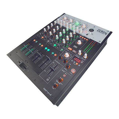
Korg
Korg ZERO 4 User manual

Korg
Korg Kaoss DJ User manual
Korg
Korg KM-402 User manual

Korg
Korg Kaoss DJ User manual

Korg
Korg KAOSS PAD KP3 User manual

Korg
Korg SoundLink MW-1608 User manual

Korg
Korg Digital Mixer ZERO4 User manual
Korg
Korg monotribe User manual

Korg
Korg EMX-1 User manual