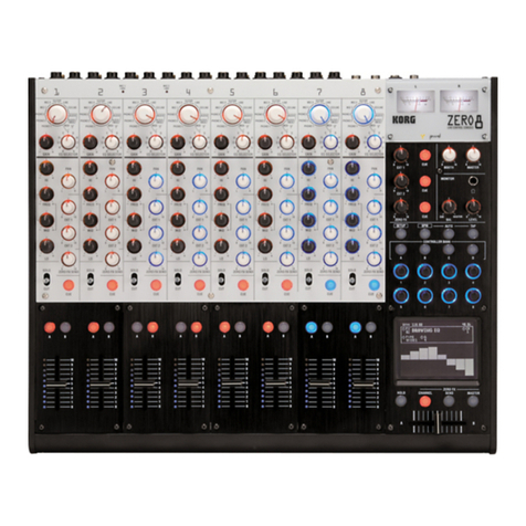
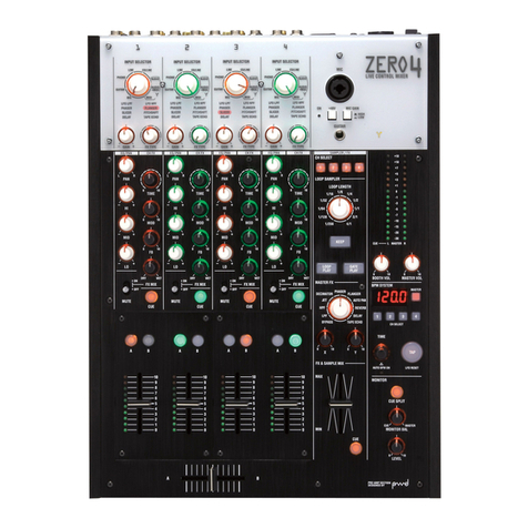
Korg Digital Mixer ZERO4 User manual


*MODE1[A,A]の場合、X-5810パネルエンコーダー用
SLOTはSCANしない


・
A
bout this check
A
fter repairing, you need not do all these checks.
P
lease do the necessary checks corresponding to the repairing.
W
hen you do the checks of Page1/10-Page4/10,
do the checks according to this manual.
P
age5/10-Page10/10 are checks for INPUTs and OUTPUTs.
T
hese are the checks that sound from INPUTs are correctly reproduced
from OUTPUTs.
Y
ou can use different equipments from this manual for these checks.
KORG INC.
ZERO4 (X-5800) Check before Shipping
Revised
No.
Date 1/12007/6/18
QCI-5800 Page

Equipments
:
・AC cord ・Audio analyzer or oscillator
・MIDI cable×1 ・D3200 x1
・XLR cable×2
・TRS standard (unbalance)--TRS standard (unbalance) cable x2
TRS standard (unbalance)--RCA Pin cable x2
・Headphones (both Standard plug and mini-plug)
1
.
Start of the Check
Connection for the Internal Check
1-1.Apearance Check
(
Translation omitted.)
P
reparation
S
et the knobs as the factory setting (see end of this manual).
C
onnect the AC cord.
*
right photo
・
AC cord
C
onnect MIDI IN and MIDI OUT as a loop.
・
M
IDI cable
IN-OUT
loop connection
1-2.How to start the Test Mode.
P
ressing the [2] and the [4] of BPM SYSTEM SECTION,
t
urn the power ON.
F
ig.1 When Internal Check
2. Internal Check
・
At first the Internal check starts in the test mode
.
(Fig1
)
・
SDRAM Check
I
nternal Check Error
①
Check of
SDRAM
<<SDRAM>>
②
When an error (Address bus or data bus) occurred,
・address bus error
the check stops and the segments (see right) are blinking
③
When the cheek has passed normally, the check proceeds to the next.
・ data bus error
・
FlashROM Check
①
Manufacturer ID and Device ID are read from the Flash ROM.
②When an error occurred,
the check stops and the segments (see right) are blinking
<<FlashROM
error
>>
③When the cheek has passed normally, the check proceeds to the next.
・
MIDI LOOP Check
<<MIDI
error
>>
①When an error occurred, the check stops and the segments (see right) are blinking
②When the cheek has passed normally, the
system version is displayed.
3
.
Confirmation of the system version
F
ig.2 Version display
the system version is displayed.
C
onfirm that the system version is 1.04 or after.
*
Confirm that it is the newest version when some version-up has been done.
P
ress the
[TAP]
.
4.SW&LED Check
All LEDs light.
4-1. All LEDs light 1, 2 and individually light
Confirm that all LEDs light in same color as the "All LEDs light 1" in page2/10 Table 1.
P
ress the
[TAP]
to proceed to the next.
Confirm that all LEDs light in same color as the "All LEDs l
i
ght
2
" in page2
/10
Table 1.
Press the
[
+48V] (upper of the GUITAR JACK)
C
onfirm that the ON LED lights.
Press the
[
+48V] (upper of the GUITAR JACK)
C
onfirm that the ON LED turned OFF..
P
ress the
[TAP]
to proceed to the next.
Confirm that all LEDs light in same color as the "
Individually light
" in page2
/10
Table 1.
P
ress the
[TAP]
to proceed to the next.
KORG INC.
1/102007/4/23
QCI-5800 Page
ZERO4 (X-5800) Check before Shipping
Revised
No.
Date

Table1 LED Check
L
EDs which are checked.
A
ll LEDs light 1
All LEDs light 2
1-4CH INPUT SELECTOR - FX TYPE - PAN - HI - MID - LO each volume
O
range
G
reen
1
-
4CH
FX TYPE
display
"LFO LPF"
-
"TAPE ECHO"
Orange
同左
1
-
4CH
GAIN
Orange
R
ed
1
-
4CH
TIME
-
MOD
-
FB
-
FX MIX
each volume
Orange
G
reen
1
-
4CH
[CUE][A][B]
each switch
Orange
G
reen
1
-
4CH FADER
LED
meter
0
-
8
:
Green
,
9
:
Orange
,
0
-
8
:
Green
,
9
:
Orange
,
10
:
Red
10
:
Red
FIREWIRE LED
(
right side of
GUITA
R INPUT)
Y
ellow
Y
ellow
SAMPLER/FX
section
[1][2][3][4]
each switch
Orange
Orange
LOOP LENGTH
volume
Orange
Orange
[KEEP][LOOP PLAY][GATE PLAY]
each switch
Orange
Orange
MASTER FX
-
X
-
Y
each volume
Orange
Orange
FX & SAMPLE MIX
[CUE]
Orange
Orange
MASTER
LED
meter
L
and R
-30
-
0
:
Green
, +1
-
+7
-30
-
0
:
Green
, +1
-
+7
:
Orange
+10
-
+
18
:
Red
:
Orange
+10
-
+
18
:
Red
BOOTH VOL
MASTER VOL
each volume
Orange
Orange
BPM SYSTEM
8
segments
LED
4digits
R
ed
R
ed
BPM SYSTEM
[MASTER][1][2][3][4]
each switch
O
range
O
range
TIME
Rotary encoder
O
range
O
range
[TAP]
switch
O
range
O
range
AUTO BPM ON
LED
O
range
O
range
[CUE SPLIT]
switch
O
range
O
range
MONITOR BAL
and
VOL
each volume
O
range
O
range
4-2.SW Check
O
perate the switches like Table 2.
*
Before this check, confirm that the all toggle switches are OFF.
Y
:Yellow
G
:Green
Table
2
SW
Check
O
:Orange
S
witches which are checked.
LED
which lights.
C
olor
N
otice
1
-
4ch
toggle switches
"FX MIX ON"→"OFF"→"MUTE"
-
-
1
-
4ch
[
CUE
]
x
2
[CUE]
O→
G
P
ress twice each.
1
-
4ch
[A][B]
each switch
x
2
[A]
or
[B]
O→
G
Press[A]twice,Press[B] twice
SAMPLER FX
CH SELECT[1]
[1]
O
SAMPLER FX
CH SELECT[2]
[2]
O
SAMPLER FX
CH SELECT[3]
[3]
O
SAMPLER FX
CH SELECT[4]
[4]
O
SAMPLER FX
の
CH SELECT
[
4
]
FIREWIRE LED
Y
Right side of GUITAR INPUT
[KEEP]
[KEEP]
O
[LOOP PLAY]
[LOOP PLAY]
O
[GATE PLAY]
[GATE PLAY]
O
BPM SYSTEM
[MASTER]
[MASTER]
O
BPM SYSTEM
CH SELECT[1]
[1]
O
BPM SYSTEM
CH SELECT[2]
[2]
O
BPM SYSTEM
CH SELECT[3]
[3]
O
BPM SYSTEM
CH SELECT[4]
[4]
O
[TAP]
[TAP]
O
TIME(
Rotary Encoder
)
SW
AUTO BPM ON LED
O
Press the TIME.
[CUE SPLIT]
[CUE SPLIT]
O
FX & SAMPLE MIX
[CUE]
[CUE]
O
X-FADER CURVE
toggle switch
-
-
F
ront
"
NORMAL
"
→
"
REVERSE
"
→
"
NORMAL
"
CH FADER CURVE
toggle switch
-
-
F
ront
"
NORMAL
"
→
"
REVERSE
"
→
"
NORMAL
"
KORG INC.
ZERO4 (X-5800) Check before Shipping
Revised
No.
Date 2/102007/4/23
QCI-5800 Page

5. TIME Rotary Encoder Check
0. The check comes to this check the segments display is like fig.1
F
ig..1
1. Set the pointer of the encoder knob to the reference position of bottom,
push the Encoder knob and reset the count to "0"
2. Rotate the encoder to the right for one around and confirm that the display is "30"
Confirm that the dot of the right bottom of the display turned ON. (Fig.2)
F
ig..2
3
. Press the
[TAP]
.
4. Rotate the encoder to the left for one around and confirm that the display is "-30"
Confirm that the dot of the right bottom of the display turned ON. (Fig.
3
)
5
.
Press the [TAP] to proceed to the next.
F
ig..3
5. A/D (volume) Check (ch.1-4)
About the 1-4ch. each volume, do the check as the following order.
F
ig..4<INPUT SELECTOR>
C
onfirm that you can move the volumes smoothly.
1
. <INPUT SELECTOR>
(
8 points' clicks, click positions are
<
left
>1-2-3-4-5-6-7-8<
right
>
.
)
Fig.
.
5
<FX TYPE>
(0)
Confirm that the segments display is like Fig.4.
(
1) Set the volume to the position of "8".
(
2) "7" is displayed in the segments LED, then set the volume to the position of "7".
(
3) "4" is displayed in the segments LED, then set the volume to the position of "4".
Fig
.
.
6<GAIN>
(
4) "2" is displayed in the segments LED, then set the volume to the position of "2".
(
5) "1" is displayed in the segments LED, then set the volume to the position of "1"
(
left end).
T
he segments LED becomes Fig.5, the proceed to the next.
Fig
.
.
7<PAN>
2.<FX TYPE>
(8points' clicks)
(
0) Confirm that the segments LED is Fig.5.
D
o the check same as
<INPUT SELECTOR>
.
Fig
.
.
8<HI>
The segments LED becomes Fig.6, the proceed to the next.
3.<GAIN> → 4.<PAN> → 5.<HI> → 6.<MID> → 7.<LO>
(with center click)
(
0) Confirm that the segments display are Fig.6-10(see right) .
Fig
.
.
9<MID>
(
1) Rotate the volume to MAX (right end).
(
2) After the color of the <GAIN> changed, rotate the volume to MIN (left end).
(3)
After the color of the <GAIN> changed, rotate the volume to the center position.
Fig
.10<LOW>
T
he segments display changed Fig.7-11, then proceed to the next.
8.<TIME> → 9.<MOD> → 10.<FB> → 11.<FX MIX>
(without click)
Fig
.11<TIME>
(0) Confirm that the segments LED is Fig.
11-14.
(
1) Rotate the volume to MAX (right end).
(
2) Delay LED is blinking, then rotate the volume to the MIN (left end).
T
he segments display changed Fig.12-15, then proceed to the next.
Fig
.12<MOD>
9. <
CH
FADER>
(
0) Confirm that the segments LED is Fig.15.
(
1) Set the CH FADER to MAX (top). Confirm that the meter LEDs beside the fader are
Fig
.13<FB>
lighting corresponding to the position of the fader.
(2)
After the LEDs of
<TIME> <MOD> <FB> <FX>
are changed to orange
set the CH FADER to MIN (bottom).
After the LEDs of
<TIME> <MOD> <FB> <FX>
changed to orange,
Fig
.14<FX MIX>
a
nd the segments display changed to Fig.16, then proceed to the next channel.
Fig
.15<FADER>
Fig
.16<INPUT SELECTOR>
KORG INC.
ZERO4 (X-5800) Check before Shipping
Revised
No.
Date 3/102007/4/23
QCI-5800 Page

7.A/D(volume) Check (others)
Confirm that you can move the volumes smoothly.
F
ig..17<LOOP LENGTH>
1.<
LOOP LENGTH
> → 2.<MASTER FX>
(11
points' clicks The click points are <left>
1-2-3-4-5-6-7-8-9-10-11
<right>)
(0)
Confirm that the segments display is like Fig.17-18.
F
ig..18<MASTER FX>
(
1) Set the volume to the position of "11".
(
2) "10" is displayed in the segments LED, then set the volume to the position of "10".
(
3) "6" is displayed in the segments LED, then set the volume to the position of "6".
(
4) "2" is displayed in the segments LED, then set the volume to the position of "2".
F
ig.19< X >
(
5) "1" is displayed in the segments LED, then set the volume to the position of "1"
(
left end)
T
he segments display becomes Fig.17-18, then the check proceeds to the next.
F
ig.20< Y >
3.<X> → 4.<Y>
(0)
Confirm that the segments display is Fig.19-20.
D
o the check same as the <TIME> volume (1) and (2).
T
he segments display becomes Fig.20-21, then the check proceeds to the next.
F
ig.21<SAMPLE MIX FADER>
5. <FX & SAMPLE MIX FADER>
(0)
Confirm that the segments display is Fig.21.
(
1) Set the FADER knob to the MAX (top).
F
ig.22<BOOTH VOL>
(2)
The LED of
MASTER L +18
has turned ON, then set the FADER to MIN(bottom)
T
he segments display becomes Fig.22, then the check proceeds to the next.
6.<BOOTH VOL> → 7.<MASTER VOL> → 8.<MONITOR BAL>
F
ig.23<MASTER VOL>
→(
Front
)9.<X-FADER CURVE> → 10.<CH FADER CURVE>
(without click)
(0)
Confirm that the segments display is like Fig.22-26.
D
o the check same as the <TIME> volume (1) and (2).
F
ig.24<MONITOR VOL>
T
he segments display becomes Fig.23-27, then the check proceeds to the next.
11.<EQ SELECTOR >
(11points clicks)
(0)
Confirm that the segments display is like Fig.22-26.
F
ig.25<X-FADER CURVE>
D
o the check same as the <LOOP LENGTH> (1)-(5).
T
he segments display becomes Fig.28, then the check proceeds to the next.
*
In this item, <LEVEL> is not checked.
F
ig.26<CH FADER CURVE>
F
ig.27<EQ SELECTOR>
8. A/D (volume) Check (CROSS FADER)
1.<CROSS FADER>(
near and sidewise fader
)
(0)
Confirm that the segments display is Fig.28.
(1)
Move the CROSS FADER between the left end and the right end
for several times and finally stop at the left end.
(2)
Confirm that the [TAP] LED is lighting.
F
ig.28<CROSS FADER>
* Note for A/D Check
<When A/D Check LED lights.>
During 9-11 A/D Check, some LED lights.
This is a guide to operation, you need not confirm the lighting.
<A/D Check Error>
During 9-11 Check, when a volume which is not checked
now
is moved,
[CUE SPRIT] LED lights and the check can not be proceed to the next.
9. Internal Check completed
Press the [TAP].
F
ig.29
Automatically the segments display changes Fig29, Fig30.
After Fig.30 is displayed turn the power off.
F
ig.30
KORG INC.
4/102007/4/23
QCI-5800 Page
ZERO4 (X-5800) Check before Shipping
Revised
No.
Date

Normal Mode Check
Preparation
*For example,
Turn the power on of D3200. Select the DemoSong"I'd Be A Fool".
this explanation uses the D3200.
P
ressing the SONG switch of the D3200, and press the "+ "or" -" for several times,
Any sound source is Ok which
w
hen
"I'd Be A Fool"
is displayed then release your fingers from the switches.
can be connected to the ZERO4.
Set the MASTER FADER of the D3200 to "0".
C
onnect the ZERO4 and the D3200 like following.
ZERO4
CH1 LINE L/MONO ― D3200 MASTER OUT L
ZERO4
CH1 LINE R ― D3200 MASTER OUT R
Check
・
C
onfirm that the setting of ZERO4 is factory setting.
・
T
urn the power on of the ZERO4.
C
onfirm that the display is "120.0".
Confirm that the TAP LED under the "120.0" is blinking.
S
et the ZERO4 like following.
BOOTH VOL, MASTER VOL->MAX (right end)
CH1
,2,3,4 MODULE FADER->MAX (top)
M
ONITOR BAL , LEVEL (right bottom side)->MAX (right end)
CH
1,2,3,4 INPUT SELECTOR->LINE
MONITOR
・
Confirmation of LINE
(
TRS
)
INPUT
.
P
ress the PLAY switch of D3200. (Demosong starts.)
Connect the headphones to the standard jack of ZERO4 MONITOR. (front left side)
Y
ou can hear the demo song of the D3200, confirm that there is not noise
and fragmentary sound.
S
et the LEVEL (right bottom side) to MIN (left end).
C
onfirm that the sound disappeared.
T
ake out the headphone plug from the standard jack and connect to the mini jack.
S
et the LEVEL (right bottom side) to MAX (right end).
Y
ou can hear the demo song of the D3200, confirm that there is not noise
and fragmentary sound.
S
et the LEVEL (right bottom side) to MIN (left end).
C
onfirm that the sound disappeared.
S
et the LEVEL (right bottom side) to MAX (right end).
T
ake out the headphone plug from the mini jack and connect to the standard jack.
*
Before CH4 the demo song
T
ake out the cable which is connected to the
CH1 LINE L/MONO
of ZERO4,
of the D3200 finished,
t
hen connect it to the CH2 LINE RL/MONO
P
ressing the STOP of D3200
P
ress the REW switch.
T
ake out the cable which is connected to the
CH1 LINE
R of ZERO4,
T
he song returns to the top.
t
hen connect it to the CH2 LINE R.
T
hen press the PLAY.
Y
ou can hear the demo song of the D3200 from CH2, confirm that there is not noise
and fragmentary sound.
S
ame as above confirm the sound (D3200 demo song) from the headphones
regarding CH3,CH4.
A
fter confirmation of the CH4,
P
ress the STOP switch of the D3200. Then the demo song stops.
P
ressing the STOP of the D3200, press the REW. (the song returns to the top.)
P
ull out the cables which are connected.
KORG INC.
ZERO4 (X-5800) Check before Shipping
Revised
No.
Date 5/102007/4/23
QCI-5800 Page

・
Confirmation of CD
/
LINE
(
RCA
)
INPUT
C
onnect the ZERO4 and the D3200 like following.
ZERO4 CH1 CD/LINE L/MONO - D3200 MASTER OUT L
ZERO4 CH1 CD/LINE R - D3200 MASTER OUT R
S
et the CH1,2,3,4 INPUT SELECTORs to "CD/LINE".
P
ress the PLAY switch of D3200. (Demo song starts.)
Connect the headphones to the standard jack of ZERO4 MONITOR. (front left side)
Y
ou can hear the demo song of the D3200, confirm that there is not noise
and fragmentary sound.
S
ame as above confirm regarding CH2,3,4 CD/LIN INPUTs.
A
fter confirmation of the CH4,
P
ress the STOP switch of the D3200. Then the demo song stops.
P
ressing the STOP of the D3200, press the REW. (the song returns to the top.)
P
ull out the cables which are connected.
KORG INC.
ZERO4 (X-5800) Check before Shipping
Revised
No.
Date 6/102007/4/23
QCI-5800 Page
Other manuals for Digital Mixer ZERO4
1
Table of contents
Other Korg Dj Equipment manuals

Korg
Korg EMX-1 User manual

Korg
Korg KAOSS PAD KP3 User manual

Korg
Korg ZERO 4 User manual

Korg
Korg Kaoss DJ User manual

Korg
Korg SoundLink MW-1608 User manual

Korg
Korg monotribe User manual

Korg
Korg KM-402 User manual

Korg
Korg Digital Mixer ZERO8 User manual
Korg
Korg SoundLink MW-1608 User manual
Korg
Korg Kaoss DJ User manual