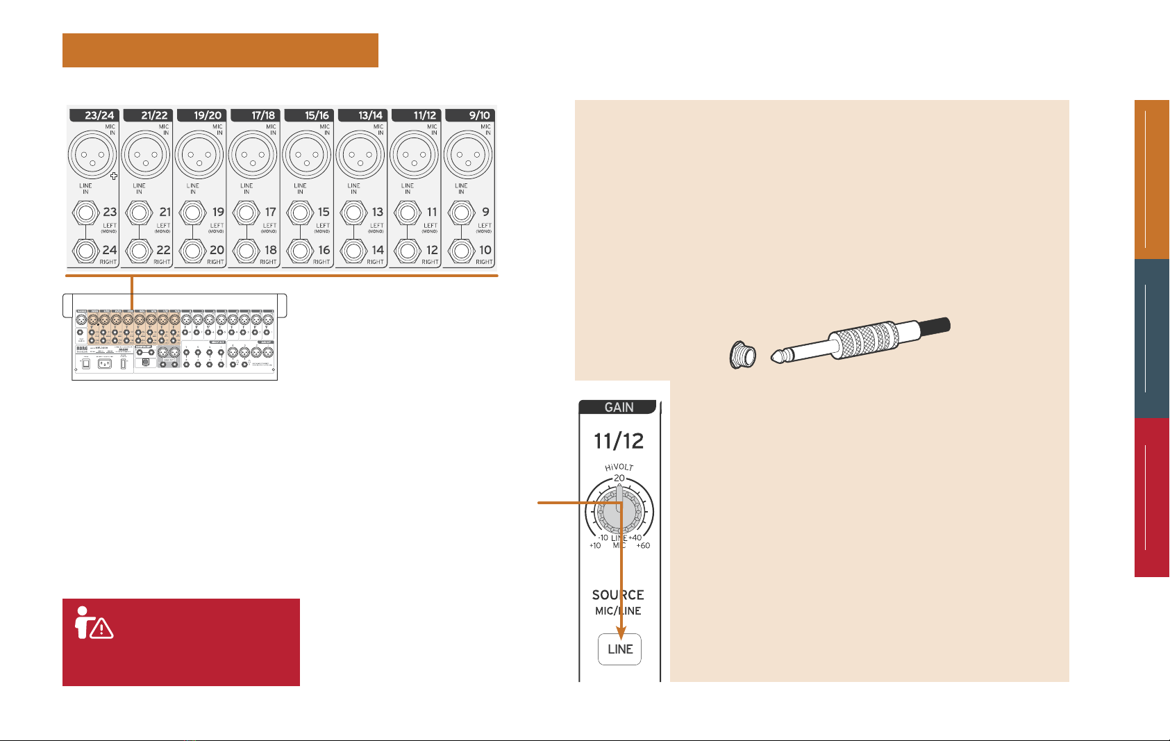
Hook-up/Back panel Analog Controls Digital Controls
2
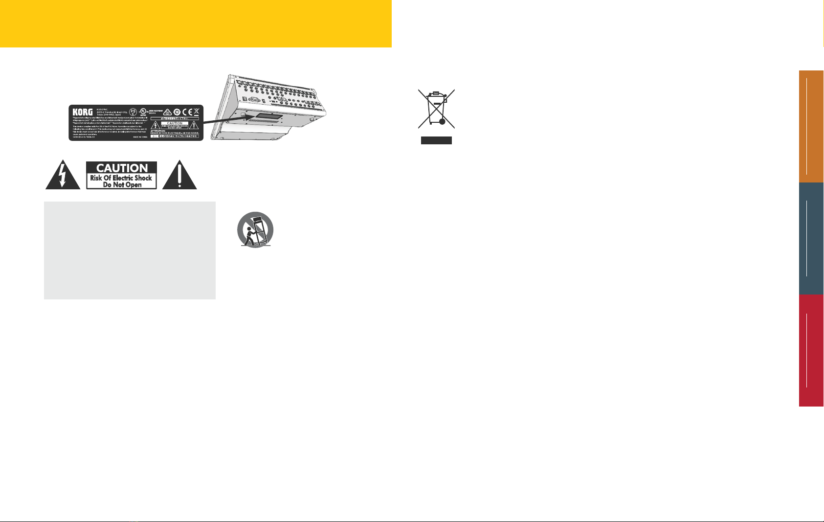
Important Safety Instructions
The lightning flash with arrowhead symbol, with-
in an equilateral triangle, is intended to alert the
user to the presence of uninsulated “dangerous
voltage” within the product’s enclosure that may
be of sucient magnitude to constitute a risk of
electric shock to persons. The exclamation point
within an equilateral triangle is intended to alert
the user to the presence of important operating
and maintenance instructions in the literature
accompanying the device.
1. Read and keep these instructions.
2. Heed all warnings.
3. Follow all instructions.
4. WARNING: To reduce the risk of fire
or electric shock, do not expose this
apparatus to rain or moisture.
5. Do not use this apparatus near water.
6. Do not block any ventilation openings.
Install in accordance with the
manufacturer’s instructions.
7. Do not install near any heat sources such
as radiators, heat registers, stoves, or other
apparatus.
8. Do not defeat the safety purpose of
the polarized or grounding type plug. A
polarized plug has two blades with one
wider than the other. A grounding type
plug has two blades and a third grounding
FCC Compliance
Supplier’s Declaration of
Conformity (for USA)
Responsible Party:
KORG USA INC
Address:
316 S. SERVICE RD. MELVILLE, NY
Telephone:
1+ 631-390-6500
Equipment Type:
HYBRID ANALOG/DIGITAL MIXER
Model:
MW-2408 / MW-1608
This device complies with part 15 of the
FCC Rules. Operation is subject to the fol-
This product complies with IEC668- safety
standards. Safety indication label is located on
the bottom panel of the unit.
prong. The
wide blade or
the third prong
are provided
for your safety.
If the provided
plug does not
fit into your
outlet, consult
an electrician for replacement of the
obsolete outlet.
9. Protect the power cord from being
walked on or pinched particularly at
plugs, convenience receptacles, and the
point where they exit from the apparatus.
10. Use only with the cart, stand,
tripod, bracket, or table
specified by the manu-
facturer, or sold with
the apparatus. When a cart
is used, use caution when moving the
cart/apparatus combination to avoid
injury from tip-over.
11. Unplug this apparatus during lightning
storms or when the apparatus has been
damaged in any way, such as power-
supply cord or plug is damaged, liquid
has been spilled or objects have fallen
into the apparatus, the apparatus has
been exposed to rain or moisture,
does not operate normally, or has been
dropped.
12. WARNING: The apparatus must be
connected to an AC power output
(MAINS) with a protective grounding
(earthing) connection.
13. Where a main AC connection (MAINS)
or appliance coupler, such as power strip
is used as the disconnect device, the
disconnect device shall remain readily
operable.
14. Only use attachments/accessories
specified by the manufacturer.
15. Clean only with dry cloth.
16. This product must be disposed of
correctly.
This symbol indicates that
this product must not be
disposed of with household
waste, according to the
WEEE Directive (2012/19/
EU) and/or your national or
regional law. This product
should be taken to a collection center
licensed for the recycling of electronic
waste and electronic equipment (EEE).
The mishandling of this type of waste
could have a possible negative impact on
the environment and human health due
to potentially hazardous substances that
are generally associated with EEE. At the
same time, your cooperation in the
correct disposal of this product will
contribute to the efficient use of natural
resources. For more information
concerning EEE recycling, contact your
local city office or your household waste
collection service.
lowing two conditions: 1)This device may not
cause harmful interference;
2) This device must accept any interference
received, including interference that may cause
undesired operation.
Note: This equipment has been tested and
found to comply with the limits for a Class B
digital device, pursuant to part 15 of the FCC
Rules. These limits are designed to provide
reasonable protection against harmful inter-
ference in both a commercial and residential
installation.
This equipment generates, uses and can
radiate radio frequency energy and, if not
installed and used in accordance with the
instructions, may cause harmful interference to
radio communications.
However, there is no guarantee that interfer-
ence will not occur in a particular installation.
If this equipment does cause harmful interfer-
ence to radio or television reception,which can
be determined by turning the equipment off
and on, the user is encouraged to try to correct
the interference by one or more of the follow-
ing measures:
1. Reorient or relocate the receiving
antenna.
2. Increase the separation between the
equipment and receiver.
3. Connect the equipment into an outlet on
a circuit different from that to which the
receiver is connected.
4. When connecting this mixer to another
product use only quality shielded cables.
5. Use AC power outlets (MAINS) that
are on a different branch circuit (circuit
breaker or fuse), or employ a power filter/
conditioner.
6. Consult the dealer or an experienced
radio/TV technician for help.
7. Unauthorized changes or modification to
this system can void the user’s authority
to operate this equipment.