KORTING KHC 9959 X User manual

КУХОННАЯ ВЫТЯЖКА KHC 9959 X

COOKER HOOD - User instructions
ODSAVAČ PAR - Návod k použití
EMHÆTTE - Brugervejledning
LIESITUULETIN – Käyttöohje
ΑΠΡΡΦΗΤΗΡΑΣ ΣΕ ΕΚ∆ΣΗ ΑΠΡΡΦΗΣΗΣ – Εγειρίδι ρήσης
ELSZÍVÓ KÜRTŐ – Használati utasítás
AVTREKKSKAPPE – Bruksanvisning
OKAP ZASYSAJĄCY - Instrukcja obsługi
HOTĂ ASPIRANTĂ – Manual de utilizare
ВЫТЯЖНОЙ КОЛПАК - Руководство пользователя
SPISKÅPA – Bruksanvisning
GB
CZ
DK
FIN
GR
H
N
PL
R
RUS
S


�
Fig.1
Fig.2
- 3 -

Fig.3
- 4 -

�
Fig.4 Fig.5
Fig.6
- 5 -

Fig.7
Fig.9
Fig.8
- 6 -

Fig.10
Fig.11
Fig.12
- 7 -

Fig.13
Fig.15
Fig.17
Fig.14
Fig.16
Fig.18
- 8 -

GENERAL
Carefully read the following important information regarding
installation safety and maintenance. Keep this information
booklet accessible for further consultations. The appliance
has been designed for use in the ducting version (air exhaust
to the outside – Fig.1B), ltering version (air circulation on the
inside – Fig.1A) or with external motor (Fig.1C).
SAFETY PRECAUTION
1. Take care when the cooker hood is operating simultane-
ously with an open replace or burner that depend on the air
in the environment and are supplied by other than electrical
energy, as the cooker hood removes the air from the environ-
ment which a burner or replace need for combustion. The
negative pressure in the environment must not exceed 4Pa
(4x10⁻⁵ bar). Provide adequate ventilation in the environment
for a safe operation of the cooker hood.
Follow the local laws applicable for external air evacuation.
Before connecting the model to the electricity network:
-Control the data plate (positioned inside the appliance)
to ascertain that the voltage and power correspond to the
network and the socket is suitable. If in doubt ask a qualied
electrician.
-If the power supply cable is damaged, it must be replaced
with another cable or a special assembly, which may be
obtained direct from the manufacturer or from theTechnical
Assistance Centre.
-This device must be connected to the supply network
through either a plug fused 3A or hardwired to a 2 fase spur
protected by 3A fuse.
2. Warning!
In certain circumstances electrical appliances may be a
danger hazard.
A)Do not check the status of the lters while the cooker
hood is operating.
B)Do nottouchbulbs or adjacentareas,duringor straight
after prolonged use of the lighting installation.
C)Flambè cooking is prohibited underneath the cooker
hood.
D)Avoid free ame, as it is damaging for the lters and a
re hazard.
E) Constantly check food frying to avoid that the
overheated oil may become a re hazard.
F) Disconnect the electrical plug prior to any
maintenance.
G)Thisapplianceisnotintendedforusebyyoungchildren
or inrm persons without supervision.
H) Youngchildrenshouldbe supervised toensurethey do
not play with the appliance
I) There shall be adequate ventilation of the room when
the rangehood is used at the same time as appliances
burning gas or other fuels.
L) There is a risk of re if cleaning is not carried out in
accordance with the instructions.
ThisapplianceconformstotheEuropeanDirectiveEC/2002/96,
Waste Electrical and Electronic Equipment (WEEE). By making
sure that this appliance is disposed of in a suitable manner, the
user is helping to prevent potential damage to the environ-
ment or to public health.
The symbol on the product or on the accompanying pa-
perwork indicates that the appliance should not be treated as
domestic waste, but should be delivered to a suitable electric
and electronic appliance recycling collection point. Follow lo-
cal guidelines when disposing of waste. For more information
on the treatment, re-use and recycling of this product, please
contact your local authority, domestic waste collection service
or the shop where the appliance was purchased.
INSTALLATION INSTRUCTIONS
•Assemblyandelectricalconnectionsmustbecarriedout
by specialised personnel.
•Wear protectivegloves before proceedingwiththe
installation.
•ElectricConnection:
Note! Verify the data label placed inside the appliance:
-If the symbol appears on the plate, it means that no earth
connection must be made on the appliance, therefore follow
the instructions concerning insulation class II.
-If the symbol DOES NOT appear on the plate, follow the
instructions concerning insulation class I.
Insulation class II
-The appliance has been manufactured as a class II, therefore
no earth cable is necessary. The plug must be easily acces-
sible after the installation of the appliance. If the appliance
is equipped with power cord without plug, a suitably di-
mensioned omnipolar switch with 3 mm minimum opening
between contacts must be tted between the appliance and
the electricity supply in compliance with the load and current
regulations.
-The connection to the mains is carried out as follows:
BROWN = Lline
BLUE = Nneutral.
Insulation class I
This is a class I, appliance and must therefore be connected
to an eecient earthing system.
-The appliance must be connected to the electricity supply
as follows:
BROWN = Lline
BLUE = Nneutral
YELLOW/GREEN = earth.
The neutral wire must be connected to the terminal with the
N symbol while the YELLOW/GREEN, wire must be connected
to the terminal by the earth symbol .
When connecting the appliance to the electricity supply, make
sure that the mains socket has an earth connection. After t-
tingtheductedcookerhood,makesurethattheelectricalplug
is in a position where it can be accessed easily. If the appliance
is connected directly to the electricity supply, an omnipolar
switch with a minimum contact opening of 3 mm must be
placed in between the two; its size must be suitable for the
load required and it must comply with current legislation.
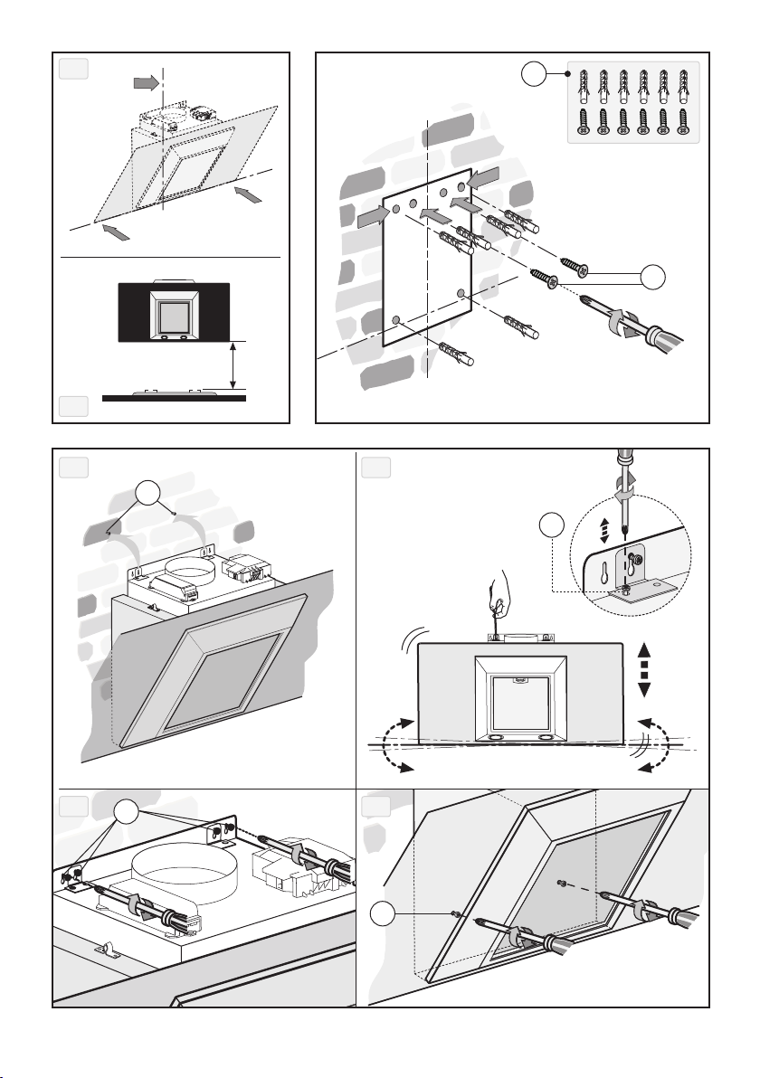
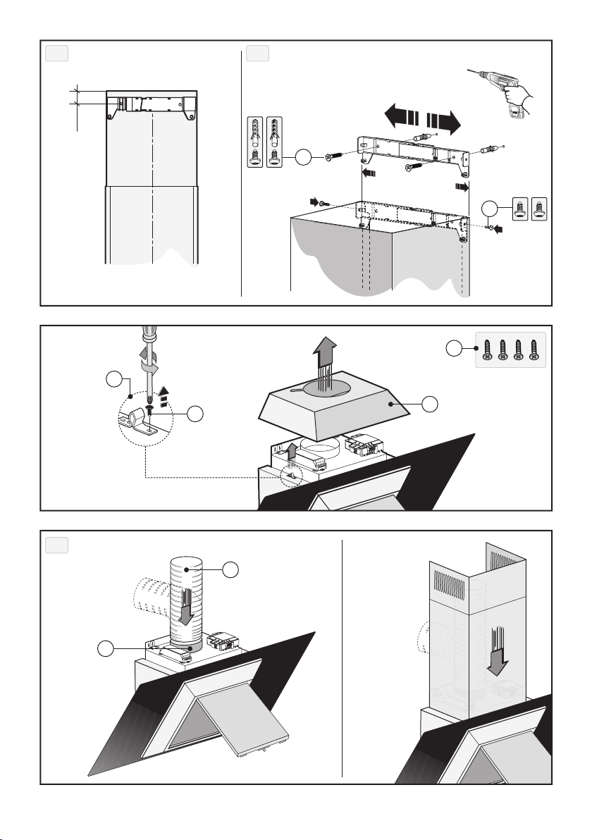
•The minimum distance between the support surfaces of
the cooking pots on the cooker top and the lowest part of
the cooker hood must be at least 45 cm. If a connection tube
composed of two parts is used, the upper part must be placed
ENGLISH GB
- 9 -

outside the lower part. Do not connect the cooker hood ex-
haust to the same conductor used to circulate hot air or for
evacuating fumes from other appliances generated by other
thanan electricalsource.Beforeproceedingwith theassembly
operations, remove the anti-grease lter(s) (Fig.2.2 - Fig.3.2)
so that the unit is easier to handle.
-In the case of assembly of the appliance in the suction version
prepare the hole for evacuation of the air.
•We recommend the use of an air exhaust tube which has the
same diameter as the air exhaust outlet hole. If a pipe with
a smaller diameter is used, the eciency of the product may
be reduced and its operation may become noisier.
•If the appliance is supplied with the small cupola Mremove
it by releasing it as indicated in Fig.2.3 - Fig.3.3.
Before proceeding with the assembly operations, for easier
manoeuvrability of the appliance disengage the anti-grease
lter by pulling handle Bas indicated in Fig.2.2 - Fig.3.2.
If one owns a model with perimeter suction panel, before
carrying out this operation, perform the following phases:
-Open panel Cas indicated in Fig.2.1 - Fig.3.1.
-If one owns the version with three Apanels release them
from the xing pins by pulling outwards (Fig.3.4) and then
remove them from safety pins N(Fig.3.4) placed inside the
hood. To put them back perform the operation in reverse
order. ATTENTION! During this disassembly and assembly
operation ensure to hold the panel securely to prevent
accidental falls.
•Wallmounting:
Trace the bottom side of the hood on the wall. Consider the
measurements shown in Fig.4A and minimum distance from
the cooking surface (Fig.4B).
-Position the xing template on the wall, making sure that
the line coincides with the line previously made on the wall.
-Mark the xing holes and cut them into the material (Fig.5).
-Fix the 2 top screws Kand screw anchors (Fig.5), without
tightening them completely.
-Position the appliance at the wall (Fig.6A).
-Make sure the 2 levelling screws Jare tightened (Fig.6B.1).
-Align the appliance horizontally using the two levelling
screws J (Fig.6B.1).
-Once the adjustment has been made, fasten the hood per-
manently using the screws K (Fig.6C - Fig.6D).
-For easy accessibility to the motor unit in the case of assistan-
ce, after having levelled and xed the appliance denitively,
we recommend that the brackets are removed (Fig.6B.1).
-When carrying out the xing operations, use only screws
and screw anchors suited to the type of wall (e.g. reinforced
concrete, plasterboard etc.).
-If the screws and screw anchors are supplied with the ap-
pliance, make sure that they are suited to the type of wall to
which the hood must be xed.
•Installationofmodelswithoutdecorativeducts:
Extractor hood
-Unclip the canopy Mand remove the grille E (Fig.7).
-Pass the power supply cable through the slot in the canopy
M, as indicated in Fig.9A.1.
-Taking the grommet H, position it between the power cable
and the slot (Fig.9A.2).
-Connect the flexible hose L(not supplied) to the hood
(Fig.9B).
-Re-position the small cupola Mpaying attention that it is
hitched perfectly to the xing pins G(Fig.9B).
•Filteringversion:
-Unclip the canopy Mand remove the grille E (Fig.7).
-Pass the power supply cable through the slot in the canopy
M, as indicated in Fig.8.1.
-Taking the grommet H, position it between the power cable
and the slot (Fig.8.2).
-Fix the small cupola Mand the grille Emaking sure that is it
perfectly hooked on to the fastening pins G(Fig.8).
•Optionalaccessories:
This model may have decorative ducts as optional accessories
- ask your retailer for information.
Before installing decorative ues it is necessary to remove
the small cupola Mand loosen the 4 screws Qthat lock the
fastening pins Gas shown in Fig.11.
•Installationofmodelswithdecorativeducts:
Extractor hood
Make sure the electrical power supply is within the measure-
ments of the decorative connector. Adjust the width of the
support bracket of the top connector (Fig.10.2). Then x it
to the ceiling so that it is on the same axis as the hood using
screws Aand observing the distance from the ceiling shown
in Fig.10.1. Connect ange Fto the air exhaust hole using
exible hose L(Fig.12A). Slide the top connector inside the
lower duct and place this on the body (Fig.12B). Pull out the
top duct as far as the bracket and secure it using screws B
(Fig.10.2). To transform the hood from a ducting version into
a ltering version, ask your dealer for the charcoal lters and
follow the installation instructions.
•Filterhood:
Please note:
The lters must be ordered from your dealer as an acces-
sory.
-To transform the hood from the SUCTION version to the
FILTERING version, charcoal lters must be ordered from
your dealer as an accessory. Two types of kit are available,
one with non-renewable lters (Fig.13) and the other with
renewable lters (washable) (Fig.14). Unlike traditional carbon
lters, this carbon lter can be washed and reactivated for
approximately 12-15 times. With normal hood use, this lter
should be cleaned once every 2-3 months. The lter can be
washed into a dishwasher at the highest temperature using a
standard dishwasher detergent. After washing, dry the lter in
the oven at 100°C for 10-15 minutes to reactivate it.The lter
will retain its odour-absorbing capacity for three years, after
which it will have to be replaced.
-If a bracket is found in the packaging like that indicated in
Fig.14 loosen the screws already installed inside the hood and
install the bracket using the previously-removed screws.
-To replace re-usable carbon filters Y, remove the brackets
from their seat, pulling them outwards (Fig.14).
-If your product is not supplied with the bracket, it means
that the active charcoal lter cannot be renewed (Fig.13).
These must be applied to the suction unit inside the hood,
centring them in it and turning them 90° until they snap into
place (Fig.13).
USE AND MAINTENANCE
•We recommend that the cooker hood is switched on before
any food is cooked. We also recommend that the appliance is
left running for 15 minutes after the food is cooked, in order
- 10 -

to thoroughly eliminate all contaminated air.
The eective performance of the cooker hood depends on
constant maintenance; the anti-grease lter and the active
carbon lter both require special attention.
•Theanti-greaselter is responsible retaining the grease
particles suspended in the air, therefore it is subject to
clogging with variable frequency according to the use of the
appliance.
- To prevent the danger of possible res, at least every 2
months one must wash the anti-grease lters by hand using
non-abrasive neutral liquid detergents or in the dishwasher
at low temperatures and on short cycles.
- After a few washes, colour alterations may occur. This does
not give the right to claim their replacement.
•Theactivecarbonlters are used to purify the air that is
sent back into the room and its function s to mitigate the
unpleasant odours produced by cooking.
- The non-regenerable active carbon lters must be replaced
at least every 4 months. The saturation of the active charcoal
depends on the more or less prolonged use of the appliance,
on the type of kitchen and on the frequency with which anti-
grease lter is cleaned.
- Regenerable active charcoal lters must be washed by hand,
with non abrasive neutral detergents, or in the dishwasher at
a maximum temperature of 65°C (the washing cycle must be
complete without dishware). Remove excess water without
damaging the lter, remove the plastic parts, and let the mat
dry in the oven for at least 15 minutes approximately at a
maximum temperature of 100°C. To keep the regenerable
charcoal lter functioning ecient this operation must be
repeated every 2 months. These must be replaced at least
every 3 years or when the mat is damaged.
•Beforeremountingtheanti-greaseltersandtherege-
nerable active charcoal lters it is important that they are
completely dry.
•Clean the hood frequently, both internally and externally,
using a cloth dampened with denatured alcohol or neutral
liquid detergents that are non abrasive.
•The lighting .system is designed for use during cooking
and not for the prolonged general lighting of the room. The
prolonged use of the lighting system signicantly decreases
the average duration of the bulbs.
•If the appliance is equipped with courtesy lights it is possible
to use them for general room lighting for a prolonged amount
of time.
•Attention: the non compliance with the hood cleaning
warnings and with the replacement and cleaning of the lters
entails risk of res. One therefore recommends keeping to the
suggested instructions.
•Replacinghalogenlightbulbs(Fig.15.1):
To replace the halogen light bulbs B, remove the glass pane
Cusing a lever action on the relevant cracks.
Replace the bulbs with new ones of the same type.
Caution: do not touch the light bulb with bare hands.
•ReplacingLEDlamps(Fig.15.2):
If the appliance version is with LED lamps, the intervention of
a specialised technician is necessary to replace them.
•CommandsLuminous(Fig.16)the key symbols are ex-
plained below:
A = LIGHT
B= OFF
C= SPEED I
D= SPEED II
E= SPEED III
F= AUTOMATIC STOP TIMER - 15 minutes (*)
If your appliance is equipped with the INTENSIVE speed
function, start from level THREE speed and keeping the but-
ton Epressed for about 2 seconds, this function activates for
about 10 minutes after which it goes back to the previously
set speed.
When the function is active the LED ashes. To interrupt it
before the 10 minutes have expired press key E again.
By pressing key F for two seconds (with the hood switched
o) the“clean air”function is activated.This function switches
the appliance on for ten minutes every hour at the rst speed.
As soon as this function is activated the motor starts up at the
rst speed for ten minutes, During this time key F and key
C must ash at the same time. After ten minutes the motor
switches o and the LED of key F remains switched on with
a xed light until the motor starts up again at the rst speed
after fty minutes and keys F and C start to ash again for ten
minutes and so on. By pressing any key for the exclusion of
the hood light the hood will return immediately to its normal
functioning (e.g. if key Dis pressed the“clean air”function is
deactivated and the motor moves to the 2nd speed straight
away. By pressing key B the function is deactivated).
(*) The “AUTOMATIC STOP TIMER” delays stopping of the
hood, which will continue functioning for 15 minutes at the
operating speed set at the time this function is activated.
•Anti-grease/activecharcoallterssaturation:
-When the Akey ashes with a 2 second frequency the anti-
grease lters must be washed.
-When the Akey ashes with a 0.5 second frequency the
active carbon lters must be replaced or washed depending
on the type of lter.
Once the clean lter has been put back one must reset the
electronic memory by pressing the Akey for approximately
5 seconds until it stops ashing.
•Commands(Fig.17):
Push-buttonA= On/o lights switch.
Push-buttonB= Switches the motor on/o. The appliance
switches on at speed level 1, If the cooker hood is on depress
the push-button for 2 sec. to switch o the cooker hood.
If the cooker hood is at speed level 1 it will not be necessary
to depress the push-button to switch the cooker hood o.
Decreases the motor speed.
Display C = Indicates the motor speed level selected and
activates the timer.
Push-buttonD= Switches the motor on. Increases the motor
speed. Touching the key at 3rd speed, the intensive function
runs for 10’, then the appliance go back to work at the original
speed. During this function the display blinks.
Key E = The Timer times the functions on activation for 15
minutes, after which they are switched o. TheTimer is deac-
tivated by re-pressing Key E. When the Timer is activated the
decimal point must ash on the display.The Timer cannot be
activated if the intensive speed is functioning.
The “clean air” function is activated by pressing key Efor 2
seconds when the appliance is switched o.This switches the
motor on for 10 minutes every hour at the rst speed. During
functioning a rotary movement of the peripheral segments
must be visualised on the display. When this time has passed
the motor switches o and the xed letter“C”must be visual-
ised on the display until the motor re-starts after 50 minutes
for another 10 minutes and so on. Press any key apart from
- 11 -

the light keys to return to normal functioning. Press key Eto
deactivate the function.
•Activecarbon/greaseltersaturation:
-When display item Cashes, at a speed where it alternates
with the letter F(e.g. 1 and F), the grease lters must be
washed.
-When display item Cashes, at a speed where it alternates
with the letter A(e.g. 1 and A), the active carbon lters must
be replaced or washed depending on the type of lter.
After the clean filter has been positioned correctly, the
electronic memory must be reset by pressing button Afor
approximately 5 seconds, until the indication For A shown
on the display Cstops ashing.
•Commands(Fig.18)Mechanicalthekey symbolsare
explained below:
A = LIGHT
B = OFF
C = SPEED I
D= SPEED II
E= SPEED III.
THE MANUFACTURER DECLINES ALL RESPONSIBILITY
FOR EVENTUAL DAMAGES CAUSED BY BREACHING THE
ABOVE WARNINGS.
- 12 -

ÚVOD’
Přečtěte si pozorně obsah návodu, protože poskytuje důležité
informace týkající se bezpečné instalace, používání i údržby
zařízení. Uchovejte si návod pro jakoukoliv budoucí potřebu.
Přístroj je určen k odsávání (odvádění vzduchu ven – Obr.1B),
filtrování (recyklace vzduchu v místnosti – Obr.1A) nebo
k použití s externě umístěným motorem (Obr.1C).
BEZPECNOSTNÍ OPATRENÍ
1. Vyžaduje se opatrnost, jestliže jsou současně v činnosti
odsávač par a jiný hořák nebo tepelné zařízení závisející na
vzduchu místnosti a napájené jinou energií než elektrickou,
protože odsávač par spotřebovává vzduch z okolí, který hořák
nebo jiné tepelné zařízení potřebují ke spalování. Negativní
tlak nesmí překročit 4Pa (4x10⁻⁵ bar). K bezpečnému provozu
je tedy nutná odpovídající ventilace místnosti. Při odvádění
vzduchu do vnějšího prostředí je nutné se řídit platnými
předpisy Vaší země.
Před napojením modelu na elektrickou síť:
-Zkontrolujte tabulku s údaji umístěnou uvnitř přístroje a
ověřte si, že napětí a výkon odpovídají místní síti a rovněž
zásuvka je vhodná.
V případě jakékoliv pochyby se poraďte s kvalikovaným
elektrikářem.
-Je-li napájecí kabel poškozen, musí být nahrazen speciálním
kabelem nebo sadou, které jsou k dispozici u výrobce nebo
v jeho servisním středisku.
-Připojte zařízení k napájení prostřednictvím zástrčky s
pojistkou 3A nebo ke dvěma vodičům dvou fází, chráněným
pojistkou 3A.
2. UPOZORNĚNÍ!
V některých situacích mohou být elektrická zařízení
zdrojem nebezpečí.
A)Nekontrolujte stav filtrů, zatímco je odsavač v
činnosti.
B)Nedotýkejte se žárovek a přilehlých prostor během
dlouhodobého použití osvětlení nebo bezprostředně po
něm.
C)Je zakázáno připravovat jídla na plameni pod
odsavačem.
D)Vyhnětesepoužitívolnýchplamenů,protožepoškozují
filtry a mohou způsobit požár.
E) Udržujte neustále pod kontrolou smažení jídel, aby se
zabránilo vznícení rozpáleného oleje.
F) Před zahájením údržby odpojte zástrčku ze zásuvky
elektrického rozvodu.
G)Zařízení není určeno pro použití dětmi nebo
nesvéprávnými osobami bez dozoru.
H) Dohlížejte na děti, abyste si byli jisti, že si nehrají se
zařízením.
I) Když je odsavač používán současně se zařízeními
spalujícímiplynnebojinápaliva,místnostsemusívhodně
větrat.
L) Kdyžnebudouřádněprovedenyúkonyúdržby, existuje
riziko vzniku požáru.
Toto zařízení je označeno v souladu s Evropskou směrnicí
2002/96/ES,WasteElectricalandElectronicEquipment(WEEE).
Tím, že se uživatel ujistí o správné likvidaci tohoto výrobku,
přispívá k předcházení případným negativním následkům na
životní prostředí a na zdraví.
Symbol na výrobku nebo na přiložené dokumentaci
poukazuje na to, že se s tímto výrobkem nesmí zacházet jako
sběžnýmdomovnímodpadem,alemusíseodeslatdovhodné
sběrny určené pro recyklaci elektrických a elektronických
zařízení. Zařízení se musíte zbavit v souladu s místními
předpisy pro likvidaci odpadu.Podrobnější informace o
zacházení s tímto výrobkem, jeho opětovným použitím a
recyklací můžete získat, když se obrátíte na příslušný místní
úřad, sběrnou službu domovního odpadu nebo obchod, ve
kterém jste výrobek zakoupili.
NÁVOD K INSTALACI
•Operacespojenésmontážíaelektrickánapojenímusí
být provedeny pouze odborným personálem.
•Používatochranné rukavicepro provádění operací
montáže.
•Elektrickézapojení:
Poznámka! Zkontrolujte štítek umístěný uvnitř zařízení:
-Když se na štítku nachází symbol , znamená to, že zařízení
nesmí být uzemněno, postupujte tudíž podle pokynů
týkajících se třídy izolace II.
-Když na štítku NENÍ uveden symbol , postupujte dle
pokynů týkajících se třídy izolace I.
Třída izolace II
Zařízení je vyrobeno v II. třídě, a proto žádný vodič nesmí
být uzemněn.
Po instalaci zařízení musí být zástrčka snadno přístupná.
V případě, že je zařízení vybaveno kabelem bez zástrčky,
je pro jeho připojení do elektrického rozvodu třeba mezi
zařízení a elektrický rozvod zapojit omnipolární stykač
s minimální vzdáleností kontaktů 3mm, navržený pro
příslušnou zátěž a odpovídající platným normám.
Napojení k elektrické síti musí být provedeno následovně:
HNĚDÁ = Lvodič
MODRÁ = N neutrální vodič
Třída izolace I
Toto zařízení je vyrobeno ve třídě I, a proto musí být připojeno
k uzemnění.
Připojení k elektrické síti musí být provedeno následovně:
HNĚDÝ = Lfázový vodič
MODRÝ = Nnulový vodič
ŽLUTO/ZELENÝ =zemnicí vodič.
Nulový vodič musí být připojen ke svorce označené symbolem
N, zatímco ŽLUTO/ZELENÝ vodič musí být připojen ke svorce
nacházející se v blízkosti symbolu uzemnění .
Během operace elektrického zapojení se ujistěte, zda je
elektrická zásuvka vybavena uzemněním.
Po uskutečnění montáže odsavače dávejte pozor, aby byla
poloha zástrčky elektrického přívodu snadno dostupná.
V případě přímého zapojení k elektrické síti je třeba mezi
zařízení a elektrickou síť zapojit omnipolární stykač s minimální
vzdáleností kontaktů 3mm, navržený pro příslušnou zátěž a
odpovídající platným normám.
•Minimální vzdálenost mezi opěrnou plochou varných nádob
na varném zažízení a nejnižším bodem kuchyňského krytu
ČESKY CZ
- 13 -

musí být alespoň 45 cm. Vývod odsavače nesmí být napojen
na vývod, ve kterém cirkuluje teplý vzduch, nebo který je
používán k odvádění kouře ze zařízení napájených jinou
energií než elektrickou. Před zahájením montáže vyjměte
z odsavače tukový ltr (Obr.2.2 - Obr.3.2). Usnadníte si tak
manipulaci s přístrojem.
- V případě montáže přístroje ve verzi odsávače je třeba
připravit otvor k evakuaci vzduchu.
•Doporučuje se použít trubku pro odvádění vzduchu se
stejným průměrem jako hrdlo výstupu vzduchu. Použití
redukce by mohlo negativně ovlivnit vlastnosti výrobku a
zvýšit hlučnost.
•Je-li přístroj vybaven horním krytem Modstraňte jej jak je
znázorněno na Obr.2.3 - Obr.3.3.
Před pokračováním v operacích montáže, pro usnadnění
manévrování s přístrojem, vyberte filtr proti mastnotě
potáhnutím rukojeti Bjak je znázorněno na Obr.2.2 -
Obr.3.2.
Pokud vlastníte model s obvodovým odsávacím panelem,
předprovedenímtétooperacejezapotřebídodržetnásledující
fáze:
-Otevřete panel Cjak je znázorněno na Obr.2.1 - Obr.3.1.
-Pokud vlastníte verzi se třemi panely Auvolněte je z
upevňujících čepů jejich potáhnutím směrem ven (Obr.3.4)
a následně je stáhněte z bezpečnostních čepů N(Obr.3.4)
nacházejících se uvnitř odsavače. PPro jejich opětovné
umístění postupujte opačně. POZOR! Během této operace
montáže a demontáže je zapotřebí se ujistit, že je panel
pevně připojen, aby nedošlo k náhodným pádům.
•Upevněnínastěnu:
Vyznačte na stěně spodní část odsavače, berouc v úvahu
rozměry uvedené na Obr.4A a minimální vzdálenost od varní
plochy (Obr.4B).
-Umístěte upevňovací šablonu na stěnu a dbejte přitom,
aby se příslušná čára shodovala s čárou naznačenou
v předcházejícím odstavci.
-Vyznačte a připravte montážní otvory (Obr.5).
-Upevněte 2 horní šrouby K, aniž byste je zcela zašroubovali;
upevněte i rozpěrné kotvy (Obr.5).
-Umístěte přístroj na stěnu (Obr.6A).
-Dávejte pozor, aby 2 vyrovnávací šrouby Jbyli utažené
(Obr.6B.1).
-Vyrovnejte přístroj do horizontální polohy pomocí dvou
vyrovnávacích šroubů J(Obr.6B.1).
-Po provedení regulace denitivně upevněte odsavač pomocí
šroubů K(Obr.6C - Obr.6D).
-Pro snadnější přístup k jednotce motoru v případě zásahu po
vyrovnávací a denitivním upevnění doporučujeme odstranit
podpěrné svorky (Obr.6B.1).
-Při různých montážích používejte šrouby a rozpěrné kotvy
vhodné pro daný druh stěny (např. z betonu, sádrokartonu
atd.).
-V případě, že se šrouby a kotvy dodávají v příslušenství
výrobku, se ujistěte, zda jsou vhodné pro daný druh stěny, ke
které má být připevněn odsavač.
•Instalacepromodelybezestetickýchkomínů:
Odsávací verze
-Odmontujte horní kryt Ma odstraňte mřížku E(Obr.7).
-Nechte projít napájecí kabel otvorem horního krytu M
znázorněným na Obr.9A.1.
-Vezměte trubku na přechod kabelů Ha umístěte ji mezi
napájecí kabel a otvor (Obr.9A.2).
-Zapojte flexibilní hadici L(není v dotaci) k odsavači
(Obr.9B).
-Opětovně umístěte horní kryt Ma dávejte přitom pozor, aby
se perfektně nasadil na čepy G (Obr.9B).
•Filtračníverze:
-Odmontujte horní kryt Ma odstraňte mřížku E(Obr.7).
-Nechte projít napájecí kabel otvorem horního krytu M
znázorněným na Obr.8.1.
-Vezměte trubku na přechod kabelů Ha umístěte ji mezi
napájecí kabel a otvor (Obr.8.2).
-Opětovně umístěte horní kryt Ma mřížku Edávejte přitom
pozor, aby se perfektně nasadili na xující čepy G(Obr.8).
•Volitelnépříslušenství:
Tento model odsavače může být v rámci volitelného
příslušenství vybaven estetickými komíny, o které je třeba
požádat vašeho prodejce. Před instalací estetických komínů
je zapotřebí odstranit horní kryt Ma odšroubovat 4 šrouby Q
, které blokují xující čepy Gjak je znázorněno na Obr.11.
•Instalacepromodelysestetickýmikomíny:
Odsávací verze
Umístěte elektrické napájení uvnitř rozměrů estetického
komínu.
Regulujte šířku podpěrné lišty vrchního estetického komínu
(Obr.10.2).
Následně ji upevněte na stěnu pomocí šroubů tak, aby
byla vyrovnána s osou vašeho odsavače Aa respektovala
vzdálenost uvedenou na Obr.10.1.
Připojte pomocí exibilní hadice L, přírubu Fk otvoru na
odvádění vzduchu (Obr.12A).
Vložte vrchní estetický komín dovnitř spodního estetického
komínu a umístěte jej na tělo odsavače (Obr.12B).
Vyjměte vrchní estetický komín až po svorku a upevněte jej
pomocí šroubů B(Obr.10.2).
Budete-li chtít změnit funkci zařízení z odsavače na ltrační
verzi, vyžádejte si u vašeho prodejce ltry s aktivním uhlíkem
a sledujte montážní pokyny.
•Filtračníverze:
Pozor!
Filtry je zapotřebí objednávat jako příslušenství u vašeho
prodejce.
-Pro transformaci odsavače z verze ODSÁVACÍ na verzi
FILTRAČNÍ musejí být uhlíkové filtry objednány jako
příslušenství u vašeho prodejce.
Máme k dispozici dva různé typy, jeden s neobnovitelnými
ltry (Obr.13) a druhý s obnovitelnými ltry (omyvatelnými)
(Obr.14).
Na rozdíl od ostatních uhlíkových ltrů se tento obnovitelný
ltr může omývat a použít dalších zhruba 12-15 krát.
Při normálním používání odsavače je zapotřebí čistit ltr
každé 2-3 měsíce.
Filtr se může mýt v myčce při maximální teplotě a s použitím
běžných čistících prostředků, určených pro myčky.
Po omytí obnovitelného ltru je zapotřebí vysušit jej v rouře
při teplotě 100° pro jeho opětovnou aktivaci.
Filtrsi zachovávásvojischopnostabsorbovatzápachypodobu
tří let, pak je nutné jej vyměnit.
-Pokud v balení najdete podpěrnou svorku jako ta, co je
znázorněna na Obr.14 je zapotřebí odšroubovat 4 šrouby
již namontované uvnitř odsavače a nainstalovat ji pomocí 4
šroubů, které jste předtím odšroubovali.
-Pro výměnu obnovitelných uhlíkových filtrů Y, vyjměte
podpěrné svorky z jejich míst potáhnutím směrem ven
(Obr.14).
- 14 -

-Pokud váš výrobek není vybaven podpěrnou svorkou,
znamená to, že aktivní uhlíkový ltr není obnovitelný (Obr.13).
Tyto se musejí aplikovat na odsávací skupinu nacházející se
uvnitř odsavače tak, že se umístí do středu odsavače a otáčí
o 90 stupňů až dokud nenastane jejich úplné zacvaknutí na
doraz (Obr.13).
POUŽITÍ A ÚDRŽBA
•Doporučujeme uvést zařízení do činnosti ještě před
zahájením přípravy jakéhokoli jídla. Doporučujeme ponechat
zařízení v činnosti i po dobu 15 minut po ukončení přípravy
jídel, aby byl kompletně odveden zapáchající vzduch. Správná
činnost odsavače je podmíněna správnou a nepřetržitou
údržbou; zvláštní pozornost je třeba věnovat protitukovému
ltru a ltru s aktivním uhlím.
•Protitukový ltr má za úkol zachycovat mastné částice
nacházející se ve vzduchu, proto je v průběhu proměnné doby
vystaven ucpávání; tato doba závisí na používání zařízení.
- Abyste předešli případnému nebezpečí požáru, je nutné
nejméně jednou za dva měsíce nutné propláchnout ltry
proti mastnotě v ruce pomocí neutrálních neabrazivních
čisticích prostředků nebo v myčce na nádobí při nízkých te-
plotách v krátkém mycím programu.
- Po několika mytích může dojít ke změně barvy. Tento jev
neopravňuje k reklamaci pro eventuální výměnu.
•Filtrysaktivnímuhlíkemslouží pro pročištění vzduchu,
který se vypouští do prostředí a pohlcují nepříjemné zápa-
chy, které vznikají během vaření.
- Aktivní uhlíkové ltry, které nelze regenerovat, je zapotřebí
měnit každé 4 měsíce. Saturace aktivního uhlíku závisí více-
méně od délky používání přístroje, typu kuchyně a pravidel-
nosti, se kterou se provádí čištění ltru proti mastnotě.
- Aktivní uhlíkové ltry, které lze regenerovat, je možné
mýt v rukou pomocí čistících neutrálních a neabrazivních
prostředků, anebo je možné je mýt v myčce na nádobí s
maximální teplotou 65°C (cyklus mytí se musí provádět
bez nádobí). Odstraňte přebytek vody bez toho, že by-
ste poškodili ltr, odstraňte části z plastů a nechte vysušit
podložku v rouře po dobu přibližně 15 minut o teplotě
maximálně 100°C. Pro udržování funkčnosti uhlíkového ltru
s možností regenerace je zapotřebí zopakovat tuto operaci
každé 2 měsíce. Tyto ltry se musí vyměnit jednou za 3 roky
anebo když je podložka poškozena.
•Předopětovnýmnamontovánímltru protimastnotě
a aktivních uhlíkových ltrů, které lze regenerovat, je
důležité, aby byli pořádně suché.
•Opakovaně čistěte odsavač, zevnitř i zvenčí, s použitím
hadru navlhčeného v denaturovaném lihu nebo neabraziv-
ních tekutých čisticích prostředcích.
•Osvětlení je navrženo pro použití během vaření a ne pro
dlouhodobější použití za účelem osvětlení okolního prostředí.
Dlouhodobější použití osvětlení výrazně snižuje průměrnou
životnost žárovek.
•Pokud je přístroj vybaven osvětlením prostředí, toto může
být používáno pro všeobecné dlouhodobé osvětlování
daného prostředí.
•Pozor: nedodržování pokynů k čištění odsavače a výměny
a čištění ltrů zapříčinit rizika požáru. Doporučuje se proto
dodržovat tyto pokyny.
•Výměnahalogenovýchžárovek(Obr.15.1):
Při výměně halogenových žárovek Bsejměte sklíčko C po jeho
nadzvednutí v místě příslušných otvorů.
Žárovky nahraďte novými žárovkami stejného druhu.
Upozornění: nedotýkejte se žárovky holýma rukama.
•VýměnažárovekLED(Obr.15.2):
Je-li verze výrobku vybavena žárovkami LED projejichvýměnu
je potřebný zásah specializovaného technika.
•Ovládání (Obr.16) Světelné následuje přehled
symbolů:
Tlačítko A= OSVĚTLENÍ
Tlačítko B= VYPNUTÍ
Tlačítko C= PRVNÍ RYCHLOST
Tlačítko D= DRUHÁ RYCHLOST
Tlačítko E = TŘETÍ RYCHLOST
Tlačítko F = ČASOVÝ SPÍNAČ AUTOMATICKÉ VYPNUTÍ 15
minut (*)
Pokud je váš přístroj vybaven funkcí rychlosti INTENZIVNÍ,
počínaje od TŘETÍ rychlosti podržením stisknutého tlačítka E
po dobu zhruba 2 vteřin dojde k aktivaci na 10 minut, pak se
automaticky vrátí na předem nastavenou rychlost.
Když je funkce aktivní, LED bliká. Pro přerušení před uplynutím
10 minut stisknout opětovně tlačítko E.
Po stisknutí tlacítka F po dobu 2 s (kryt je vypnut) bude
aktivována funkce “clean air”. Tato funkce zapne motor na
deset minut každou hodinuna první rychlost. Jakmile bude
tatofunkceaktivována,motorbudeuvedendo chodunaprvní
rychlost po dobu 10 s, behem které budou blikat soucasne
tlacítka F a C. Po uplynutí této doby se motor vypne a led
tlacítka Fzustane osvetlen až do doby, kdy po 50 minutách
bude znovu motor uveden do chodu na první rychlost a led
F a C znovu zacnou blikat po 10 minut a tak dále. Stisknutím
kteréhokoli tlačítka, kromě tlačítek osvětlení, se odsavač vrátí
ke svému normálnímu fungování (např. stisknutím tlačítka
Dse deaktivuje funkce “clean air” a motor se nastaví na 2°
rychlost; stisknutím tlačítka Bse funkce deaktivuje).
(*) Funkce “ČASOVÝ SPÍNAČ AUTOMATICKÉ VYPNUTÍ”
opožďuje vypnutí odsávače, který bude pokračovat ve funkci
pracovní rychlostí, která byla nastavena v okamžiku zapnutí
této funkce, 15 minut.
•Nasyceníprotitukovýchltrů/ltrůsaktivnímuhlím:
-BlikánítlačítkaAfrekvencí 2 sek. poukazujenapotřebuumytí
protitukových ltrů.
-Když tlačítko Abliká s frekvencí 0,5 sek. , ltry s aktivním
uhlíkem je třeba umýt anebo vyměnit v závislosti od typu
ltru.
Po vložení čistého ltru je třeba vynulovat elektronickou
paměť stisknutím tlačítka Ana dobu přibližně 5 sek., dokud
tlačítko nepřestane blikat.
•Ovládání(Obr.17):
Tlačítko A = Rozsvítí/zhasne světla.
Tlačítko B = Zapne/vypne odsávač. Přístroj je uveden do
chodu při první rychlosti. Je-li odsavač zapnutý, vypněte jej
stisknutím tlačítka na 2 sek. Pokud se odsávač nachází ve fázi
první rychlosti, není nezbytné dlouze stisknout tlačítko za
účelem vypnutí. Snižuje se rychlost motoru.
Displej C = Ukazuje zvolenou rychlost motoru a uvedení do
chodu časového spínače.
Tlačítko D =Zapne odsávač. Zvyšuje rychlost motoru.
Stiskne-li se tlačítko od třetí rychlosti, je nastavena intenzívní
funkce na 10 vteřin, pak se přístroj vrátí do fáze pracovní
rychlosti v okamžiku uvedení do chodu. Během této funkce
displej bliká.
Tlačítko E = Časovač slouží k časovému ovládání funkcí
v průběhu 15 minut po jeho aktivaci; po uplynutí uvedené
- 15 -

doby se tyto funkce vypnou. Vypnutí časovače se provádí
stisknutím tlačítka E. Aktivace funkce časovače musí být
signalizována blikáním desetinné tečky na displeji. Je-li
aktivována intenzivní rychlost, aktivace časovače není
možná.
Stisknutím tlačítka E na 2 sekundy při vypnutém zařízení
se aktivuje funkce “clean air”. V rámci této funkce se motor
zapne každou hodinu na 10 minut a během této doby se bude
otáčet první rychlostí. Během jeho činnosti bude na displeji
zobrazen rotační pohyb obvodových segmentů. Po uplynutí
uvedené doby dojde k vypnutí motoru a na displeji musí
být zobrazeno písmeno “C”, aniž by blikalo, dokud nebude
po uplynutí dalších 50 minut motor znovu spuštěn na 10
minut, a tak dále. Pro návrat k normálnímu provozu stiskněte
jakékoliv tlačítko kromě tlačítek světel. Pro deaktivaci funkce
stiskněte tlačítko E.
•Nasyceníprotitukovýchltrů/ltrůsaktivnímuhlím:
-Když displej Cbliká a střídavě zobrazuje provozní rychlost a
písmeno F (např.1 a F), je třeba vyčistit protitukové ltry.
-Když displej Cbliká, měníc rychlost provozu s písmenem A
(např.1 a A) znamená to, že uhlíkové ltry je třeba vyměnit
anebo vyčistit v závislosti od typu ltru.
Po vložení čistého ltru je třeba vynulovat elektronickou
paměť stisknutím tlačítka Ana dobu přibližně 5 sek., dokud
signalizace F nebo A na displeji C nepřestane blikat.
•PovelyMechanické(Obr.18):
A = tlačítko osvětlení
B = tlačítko vypnuto (OFF)
C = tlačítko rychlost I
D= rychlost II
E = rychlost III.
VÝROBCE ODMÍTÁ JAKOUKOLIV ZODPOVĚDNOST
ZA ŠKODY ZPŮSOBENÉ NEDODRŽENÍM UVEDENÝCH
UPOZORNĚNÍ.
- 16 -

GENERELLE OPLYSNINGER
Læs omhyggeligt indholdet af denne brugsanvisning, da
den giver vigtige oplysninger vedrørende sikkerheden
ved installering, brug og vedligeholdelse. Opbevar
brugsanvisningen til senere brug. Apparatet er udarbejdet
til at kunne fungere; udsugende (udledning af luft til eksterne
omgivelser Fig.1B), ltrerende (intern cirkulation af luft Fig.1A)
og med udvendig motor (Fig.1C).
OPLYSNINGER VEDRØRENDE SIKKERHED
1. Udvis forsigtighed hvis der samtidigt med emhætten er en
varmekilde eller amme i funktion, som er afhængig af luften
i omgivelserne og forsynet med energi, der ikke er elektrisk,
eftersom emhætten erner den luft fra omgivelserne, som
ammen eller varmekilden har brug for til forbrænding. Det
negative tryk i lokalet må ikke overstige 4 Pa (4x10⁻⁵ bar).
For størst mulig sikkerhed, sørg for en passende ventilation
af rummet. Hvad angår udsugningen til eksterne omgivelser
følg de gældende normer.
Førmodellentilsluttesel-nettet:
-Kontrollèr informationsetiketten (placeret indeni apparatet),
for at sikre, at spændingen og styrken er i overensstemmelse
med el-nettet og at stikkontakterne er egnede. Hvis De er i
tvivl, konsultèr en kvaliceret elektriker.
-Hvis forsyningsledningen er beskadiget, skal den udskiftes
med en ledning eller en særlig samling fra fabrikanten eller
et autoriseret servicecenter.
-Tilslut forsyningsenheden ved hjælp af et stik med en 3A
sikring eller til de to tofaseledninger, som er beskyttet af en
3A sikring.
2. Pas på!
I nogle situationer kan elektriske apparater udgøre en
fare.
A)Undgå at kontrollere filtrenes tilstand mens emhætten
er i funktion.
B)Rørikkevedpærerellertilstødendeområderundereller
lige efter længerevarende brug af belysningsanlægget.
C)Det er ikke tilladt at tilberede madvarer for åben ild
under emhætten.
D)Undgå åben ild, da det kan beskadige filtrene og
medføre fare for brand.
E) Hold altid øje med maden under friturestegning for at
undgå, at olien antændes.
F) Træk stikket ud af stikkontakten, inden der foretages
vedligeholdelse.
G)Apparatet må ikke bruges af børn eller af personer, der
ikke har de mentale eller fysiske egenskaber til korrekt
brug, uden overvågning.
H) Hold øje med børnene for at sikre, at de ikke leger med
apparatet.
I) Når emhætten anvendes samtidigt med apparater, der
bruger gas eller andre brændstoffer, skal rummet have
tilstrækkelig udluftning.
L) Hvis rengøring ikke udføres i overensstemmelse med
anvisningerne, kan det medføre brandfare.
Dette apparat er udviklet i overensstemmelse med det
europæiske direktiv 2002/96/EF om aald af elektrisk og
elektronisk udstyr (WEEE). Ved at sikre sig, at dette produkt
bortskaes på korrekt vis, bidrager brugeren til at forhindre
eventuelle negative miljømæssige og sundhedsmæssige
påvirkninger.
Symbolet påproduktetellerpådokumentationen,derfølger
med produktet, angiver, at produktet ikke skal behandles som
husholdningsaald, men at det skal bortskaes på passende
vis på genbrugsstationer til elektriske og elektroniske
apparater. Apparatetskalbortskaesioverensstemmelse med
de gældende regler for bortskaelse af aald. For yderligere
oplysninger om håndtering, genvinding og genbrug af dette
produkt, bedes man kontakte de lokale myndigheder, teknisk
forvaltning eller forretningen, hvor produktet er købt.
INSTRUKTION VED INSTALLERING
•Monteringenogudførelsenafdeelektriskeforbindelser,
skal udføres af specialiseret personale.
•Indenmangårfremmedmonteringen,skalmaniføre
sig beskyttelseshandsker.
•Denelektriskeforbindelse:
Bemærk! Kontroller typeskiltet inden i apparatet.
-Hvis der på skiltet ndes symbolet , betyder det,
at apparatet ikke skal jordes. Følg anvisningerne for
isoleringsklasse II.
-Hvis der på skiltet IKKE vises symbolet , skal man følge
anvisningerne for isoleringsklasse I.
Isoleringsklasse II
Apparatet er udarbejdet i klasse II, derfor skal der ikke tilsluttes
et kabel til jordforbindelsen.
Man skal nemt kunne nå ind til stikket efter installation af
apparatet.
Hvis apparatet er udstyret med ledning uden stik, skal
man ved tilkobling til strømforsyningen sørge for, at der
mellem apparatet og strømforsyningen er installeret en
erpolet afbryder med en åbning på minimum 3mm mellem
kontakterne, som passer til belastningen og overholder de
gældende regler.
Tilslutning til el-nettet skal udføres som følgende:
BRUN = Llinje
BLÅ = Nneutal.
Isoleringsklasse I
Dette apparat er konstrueret i klasse I og skal derfor tilsluttes
til et stik med jordforbindelse.
Tilslutningen til strømforsyningen skal udføres på følgende
måde:
BRUN = Llinje
BLÅ = Nneutral
GUL/GRØNNE = jord.
Den neutrale ledning skal tilsluttes til klemrækken med
symbolet N mens den GUL/GRØNNE skal tilsluttes til
klemrækken ud for jordsymbolet .
Når den elektriske tilslutning udføres, skal man sikre sig, at
strømstikketharjordforbindelse.Eftermonteringaf emhætten
skal man sikre sig, at stikkontakten nemt kan nås. Ved direkte
tilslutning til strømforsyningen skal der mellem apparatet og
strømforsyningsnettet monteres en erpolet afbryder med en
minimumsafstand mellem kontakterne på 3mm, der kan klare
belastningen og overholder de gældende regler.
DANSK DK
- 17 -

•Minimums distancen mellem kogeoveraden, målt fra selve
kogepladerne, og den nederste del af emhætten, skal være
mindst 45 cm. Hvis der anvendes et forbindelsesrør bestående
af to eller ere dele, skal den øverste del placeres udenpå den
nederste. Tilslut ikke udledningen fra emhætten med et rør,
hvori der cirkulerer varm luft eller som anvendes til at udlede
røg fra apparater, der ikke bruger elektrisk energi. Inden man
begynder monteringen ernes ltret (Fig.2.2 - Fig. 3.2) for at
gøre håndteringen af apparatet lettere.
- I de tilfælde, hvor apparatet skal installeres i en udsugende
version, forberedes åbningen til udledning af luft.
•Det anbefales at anvende en luftudsugningsslange med
sammediametersomluftudgangshullet.Hvisderanvendesen
mindre slange, kan det forringe produktets ydelse og medføre
øget støj.
•Hvis apparatet er udstyret med lille kuppel M,skaldenernes
ved at løse den, som det angives på Fig.2.3 - Fig. 3.3.
Inden monteringen påbegyndes, ernes fedtlteret ved at
trække i håndtaget B,som vist i Fig.2.2 - Fig.3.2, for at gøre
håndteringen af apparatet lettere.
Hvis man ejer en model med perimeter udsugningspanel, skal
følgende foretages, inden denne operation udføres:
-Åbne panel C, som det angives på Fig.2.1 - Fig.3.1.
-Hvis man ejer en model med tre Apaneler, afhægtes de
fastspændingsboltene ved at trække udad (Fig.3.4) og
efterfølgende trække dem ud af sikkerhedsboltene N(Fig.3.4),
som ndes inden i emhætten. For at sætte dem fast igen
udføres operationen i omvendt rækkefølge. PAS PÅ! Under
afmonteringenogmonteringenskaldetsikres,atpanelets
ophæng er fast for at undgå utilsigtede fald.
•Fastøringtilvæggen:
Tracéremhættensunderkantpå væggenvedattagehensyntil
de angivne mål i Fig.4A, og af den minimale krævede afstand
fra kogeplanen (Fig.4B).
-Placér skabelonen på væggen, og sørg for, at linjen passer
med den, der blev afmærket i forrige trin.
-Markér og bor huller til montering (Fig.5).
-Fastgør de 2 øverste skruer K, uden at skrue dem helt i, og
rawlplugs (Fig.5).
-Positionér apparatet på væggen (Fig.5A).
-Kontroller at de 2 nivelleringsskruer Jer godt strammet
(Fig.6B.1).
-Linjestil apparatet i vandret position, ved at virke på de to
nivelleringsskruer J (Fig.6B.1).
-Når reguleringen er fuldført, fastgør emhætten fuldstændigt
med skruerne K(Fig.6C - Fig.6D).
-For at have en nemmere adgang når der kræves assistance,
tilrådes det, efter at have fuldstændigt nivelleret og fastgjort
apparatet, at erne bøjlerne (Fig.6B.1).
-Der skal anvendes skruer og rawlplugs, der passer til
vægtypen (f.eks. armeret beton, gipsvæg osv.).
-Hvis der følger skruer og rawlplugs med, skal man først
sikre sig, at de passer til den type væg, som emhætten skal
monteres på.
•Installationpåmodellerudendekorativpejs:
Udsugende version
-Løsn den lille kuppel Mog ern rillen E(Fig.7).
-Før elforsyningskablet gennem det splejsede øje på den lille
kuppel M, som det angives på Fig.9A.1.
-Tag fat i kabelholder Hog positioner den mellem
forsyningskablet og det splejsede øje (Fig.9A.2).
-Forbind slangen L(der ikke medleveres) til emhætten
(Fig.9B).
-Sæt den lille kuppel Mpå plads igen, ved at sørge for at den
hægtes ordentligt til fastgøringstapperne G(Fig.9B).
•Filtrerendeversion:
-Løsn den lille kuppel Mog ern rillen E (Fig.7).
-Før forsyningskablet gennem det splejsede øje på den lille
kuppel M, som angivet i Fig.8.1.
-Tag fat i kabelholder Hog positioner den mellem
forsyningskablet og det splejsede øje (Fig.8.2).
-Fastgør den lille kuppel Mog rillen Eved at sørge for at den
hægtes ordentligt til fastgøringstapperne G(Fig.8).
•Optional:
Til denne emhættemodel fås afskærmning som ekstraudstyr
på efterspørgsel hos forhandleren.
Inden man installerer den dekorative pejs, skal man erne
den lille kuppel M, og løsne de 4 skruer Q, som blokerer
fastgøringstapper G, som angivet på Fig.11.
•Installationpåmodellermeddekorativpejs:
Udsugende version
Den elektriske forsyning skal indrettes indenfor ydre målene
på den dekorative pejs.
Reguler støttebøjlens bredde til overdelen på den dekorative
pejs (Fig.10.2).
Fastgør derefter bøjlen til væggen, ved hjælp af skruerne A,
sådan at den er i akse med emhætten, og at den respekterer
afstanden angivet på Fig.10.1.
Med slangen L, forbind flangen Ftil udstødningshullet
(Fig.12A).
Placer overdelen til den dekorative pejs ind i pejsens underdel,
og placer begge dele over emhætten (Fig.12B).
Træk overdelen til den dekorative pejs ud, helt hen til bøjlen,
og fastgør den med skruerne B(Fig.10.2).
Skal emhætten laves om fra aftræk til ltrering, anskaes
kulltre hos forhandleren, hvorefter monteringsvejlednin-
gen følges.
•Filtrerendeversion:
Pas på!
Filtrene skal bestilles hos forhandleren, som ekstradel.
-For at transformere emhætten version UDSUGENDE
til version FILTRERENDE, skal kulfiltrene bestilles hos
forhandleren som ekstradel.
Der er to forskellige typer Kit til rådighed, den ene med
ikke genanvendelige filtre (Fig.13) og den anden med
genanvendelige ltre (kan vasken) (Fig.14).
Som forskel med de andre kulltre, kan dette lter vaskes og
anvendes igen for andre cirka 12-15 gange.
Ved normal anvendelse af emhætten, skal dette lter rengøres
hver 2-3 måneder.
Filtret kan vaskes i opvaskemaskinen på maksimum
temperatur, ved at bruge et almindeligt rengøringsmiddel
til opvaskemaskine.
Efter vask, er det nødvendigt at genaktivere ltret, ved at tørre
i ovnen på 100° temperatur for 15-20 minutter.
Filtret vil beholde dets sugeevne til lugt, i tre år, efter denne
tid, bør den udskiftes.
-Hvis der, i emballagen, ndes en bøjle, som den der angives
på Fig.14, skal man løsne de 4 skruer, allerede installeret i
emhætten, og installere bøjlen, med de samme 4 ernede
skruer.
-For at udskifte de genanvendelige kulltre Y, skal man erne
bøjlerne fra deres sæde, ved at trække dem udad (Fig.14).
-Hvis produktet ikke er udstyret med bøjle, betyder det at de
- 18 -

aktive kulltre ikke er genanvendelige (Fig.13).
Disse skal anvendes på trækenheden, der findes inde i
emhætten, de skal stilles midt på og drejes 90° grader, indtil
man hører et stoppeklik (Fig.13).
BRUG OG VEDLIGEHOLDELSE
•Det anbefales, at apparatet sættes i funktion, inden man
begynder tilberedningen af madvarer. Det anbefales, at lade
emhætten køre i 15 minutter efter endt tilberedning, så al
mados suges ud. Korrekt funktion af emhætten afhænger af
en korrekt og jævnlig vedligeholdelse. Man skal især være op-
mærksom med at udskifte fedtlteret og det aktive kullter.
•Fedtlteret har til opgave at tilbageholde de fedtpartikler,
der ndes i luften. Filteret vil derfor blive tilstoppet med tiden,
alt efter hvor ofte emhætten anvendes.
- For at forebygge faren for eventuelle brande skal fedtlteret
mindst hver 2. måned vaskes i hånden med ydende neutrale
ikke slibende rengøringsmidler eller i opvaskemaskine ved
lav temperatur og kort program.
- Efter nogle vaske kan der forekomme farveændringer.
Dette giver ikke ret til at kræve udskiftning af ltrene.
•De aktive kulltre renser luften, der genudledes i om-
givelserne, og tjener til at dæmpe ubehagelige lugte, som
dannes ved madtilberednin.
- De ikke-regenererende aktive kulltre skal udskiftes min-
dst hver 4. måned. Mætningen af det aktive kul afhænger af
den mere eller mindre længerevarende brug af emhætten,
af hvilken slags mad der tilberedes og af regelmæssigheden
af rengøringen af fedtlteret.
- De regenererende aktive kulltre skal vaskes i hånden
med ydende neutrale ikke slibende rengøringsmidler eller
i opvaskemaskine ved højst 65°C (vaskecyklussen skal være
komplet uden anden opvask i maskinen). Fjern overskyden-
de vand uden at ødelægge ltret, ern plastikdelene og tør
ltermåtten i ovnen i mindst 15 minutter ved en temperatur
på højst 100°C. For at opretholde det regenererende aktive
kullters eektive funktion skal denne operation foretages
hver 2. måned. Filtrene skal udskiftes mindst hvert 3. år, eller
når ltermåtten er beskadiget.
•Detervigtigt,atfedtltreneogderegenererendeakti-
ve kulltre er helt tørre, inden de genmonteres.
•Emhætten skal rengøres jævnligt, både indvendigt og ud-
vendigt, med en klud opvædet i denatureret alkohol eller et
neutralt, ikke slibende rengøringsmiddel.
•Lyset er beregnet til brug under tilberedning af mad og ikke
til generel oplysning af lokalet. Længerevarende brug af lyset
vil reducere lyspærernes gennemsnitlige levetid betydeligt.
•Hvis apparatet er forsynet med rumoplysning , kan dette
anvendes til længerevarende generel oplysning af lokalet.
•Pas på: manglende udførsel af udskiftning og rengøring af
ltrene medfører brandfare. Det anbefales derfor at overholde
de foreslåede instruktioner.
•Udskiftningafhalogenpćrer(Fig.15.1):
For at udskifte halogenpćrerne Bskal man erne glasset C
ved at trykke pĺ rillerne.
Udskift pćrerne med pćrer af samme type.
Vćropmćrksom: rřr ikke ved pćren med bare hćnder.
•UdskiftningafLEDlamperne(Fig.15.2):
Hvis apparatets version er udstyret med LED lamper, skal disse
udskiftes af en specialiseret teknikker.
•Betjening-senhed:(Fig.16) LYSENDE er følgende
tegnforklaring gældende:
A = tast for BELYSNING
B = tast for OFF
C = tast for FØRSTE HASTIGHED
D= tast for ANDEN HASTIGHED
E= tast for TREDJE HASTIGHED
F= tast for TIMER AUTOMATISK STOP 15 minutter (*)
Hvis Deres apparat er udstyret med funktionen INTENSIV
hastighed vil denne, ved at starte fra TREDJE hastighed og
ved at holde taste Etrykket i cirka 2 sekunder, aktiveres i
10 minutter hvorefter den vil gå tilbage til den forinden
indstillede hastighed. Når funktionen er aktiv og blinker LED’
et. For at afbryde den inden de 10 minutter skal man trykke
taste Eigen.
Ved at trykke på knappen F i 2 sekunder(vedslukketemhætte)
aktiveres funktionen “clean air”. Denne funktion tænder
motoren i 10 minutter pr. time ved laveste hastighed. Så snart
funktionen er igangsat starter motoren ved første hastighed
i 10 minutter, og under dette forløb skal lamperne ved knap
F og knap C blinke samtidigt. Når tiden er gået standser
motoren og kontrollampen ved knap F forbliver tændt uden
at blinke indtil der er gået endnu 50 minutter, hvor motoren
igen starter ved første hastighed, og lamperne ved F og C igen
begynder at blinke samtidigt i 10 minutter, og så fremdeles.
Ved at trykke hvilken som helst tast, undtagen lysene, vil
emhætten gå tilbage til standard funktion (f. eks. ved at
trykke på tast Ddeaktiveres funktion“clean air” og motoren
indstilles på 2° hastighed; ved at trykke på tast Bdeaktiveres
denne funktion).
(*) Funktionen “TIMER AUTOMATISK STOP” forsinker
standsning af hætten, som vil fortsætte med at være tændt
(i 15 minutter) med den driftshastighed, der var i kraft i det
øjeblik funktionen blev tilsluttet.
•Mćtningaffedtltre/aktivekulltre:
-Nĺr tasten Ablinker med 2 sek. mellemrum, skal fedtltrene
rengřres.
-Når tasten Ablinker med 0,5 sek. mellemrum, skal de aktive
kulltre vaskes eller udskiftes afhængigt af ltertypen.
Nĺr filteret er sat pĺ plads igen, skal den elektroniske
hukommelse nulstilles ved at holde tasten Anede i ca. 5 sek.
indtil den stopper med at blinke.
•Betjening-senhed(Fig.17):
Tast A = Tænder/slukker lysene.
Tast B = Tænder/slukker emhætten. Apparatet tændes på 1.
hastighed. Hvis emhætten er tændt skal man trykke på tasten i
2 sek. for at slukke. Hvis emhætten er indstillet på 1. hastighed
er det ikke nødvendigt at holde tasten trykket for at slukke.
Sænker motorhastigheden.
Display C = Viser den valgte motorhastighed og aktivering
af timer’en.
Tast D = Tænder emhætten. Øger motorhastigheden.Ved tryk
på tasten fra 3. hastighed tændes den intensive funktion i 10
minutter, hvorefter apparatet vender tilbage til at fungere
med den almindelige hastighed, der var indstillet det øjeblik,
hvor den intensive funktion blev tændt. Under denne funktion
blinker displayet.
Tast E = Når timeren aktiveres, indstiller den funktionerne
til at fortsætte i 15 minutter, hvorefter de slukkes. Timeren
slås fra ved at trykke på tasten E. Når funktionen Timer er
tændt, blinker decimaltallet på displayet. Hvis funktionen
til indstilling af hastighed er aktiveret, fungerer funktionen
Timer ikke.
Hvis tasten E trykkes ned i 2 sekunder, når emhætten er sluk-
- 19 -
Table of contents
Languages:
Other KORTING Ventilation Hood manuals

KORTING
KORTING KHC 6951 X User manual

KORTING
KORTING KHA 7950 X Cube User manual

KORTING
KORTING KHC 6430 W User manual

KORTING
KORTING KHP 6772 X User manual

KORTING
KORTING KHC 6930 RC User manual

KORTING
KORTING KHT 5230 User manual

KORTING
KORTING KHC 6770 GW User manual

KORTING
KORTING KHA 4970 X Cylinder User manual

KORTING
KORTING KHP 6211 X User manual

KORTING
KORTING KWHC60S User manual