Koso REXA Electraulic Xpac User manual

IOM 05/09

Xpac Installation Manual -- Version 5.1 (5/08)
REXA
Electraulic Actuators & Drives
2

Xpac Installation Manual -- Version 5.1 (5/08)
REXA
Electraulic Actuators & Drives i
Contents:
Safety Considerations iv
INTRODUCTION 1
1 OVERVIEW 3
1.1 Actuator 4
1.2 Control Enclosure 5
1.3 Menu Calibration 5
1.4 Operational Summary 5
1.5 Optional Equipment 7
1.5.1 Position Transmitters 7
1.5.2 Manual Override 7
1.5.3 Limit Switches 7
1.5.4 Alarm Relay 7
1.5.5 Surge Control 7
1.5.6 Pulse Input 8
1.5.7 Auxiliary Controls - External 8
1.5.8 Auxiliary Controls - Remote Manual 8
1.5.9 Spring Failure 8
1.5.10 Accumulator Failure 8
1.5.11 Stem Boot 8
1.5.12 Split Clamps 9
2 DELIVERY 10
2.1 Receipt 10
2.2 Storage 10
2.3 Unpacking 10
3 OIL
11
3.1 Level Check 11
3.2 Filling 11
3.3 Oil Weeping 12
4 MECHANICAL INSTALLATION 13
4.1 R Series (Rotary) 13
4.1.1 Fail In Place Installation 13
4.1.2 Universal Rotary Spring Failure 13
4.1.3 Stroke and Adjust Option 14
4.2 L Series (Linear) 14
4.2.1 Elastic Coupling 14
4.2.2 Fail In Place Installation 16
4.2.3 Linear Spring Failure 16
4.3 D Series (Drive) 17
4.3.1 Mounting 17
4.3.2 Drive Arm 18
4.4 Control Enclosure 19
5 ELECTRICAL INSTALLATION
20
5.1 Motor Power Cable 20
5.1.1 Enclosure Termination 21
5.1.2 Actuator Termination 21
5.2 Feedback Cable 22
5.2.1 Enclosure Termination 22
5.2.2 Actuator Termination 22
5.3 User Connections 24
!

Xpac Installation Manual -- Version 5.1 (5/08)
REXA
Electraulic Actuators & Drives
ii
5.3.1 Actuator Power 24
5.3.2 Control Signals 25
6 OPERATION 29
6.1 Auto Mode 29
6.2 LOCAL Mode 30
6.3 SEtUP Mode 31
6.3.1 Cal - Calibration Sub-Menu 32
6.3.2 ACC - Acceleration Sub-Menu 35
6.3.3 CtL - Control Sub-Menu 36
7 START-UP CONSIDERATIONS 38
7.1 Wiring 38
7.1.1 Module Cable 38
7.1.2 Feedback Cable 38
7.1.3 Electrical Power 38
7.2 Electrical Noise 39
7.2.1 Provide A Good Earth Ground 39
7.2.2 Options If Actuator Is Still Noisy 39
7.2.3 Noise Pick-up On Surrounding Equipment 40
7.3 Mechanical Restriction/ Binding 40
7.3.1 Lateral Misalignment 40
7.3.2 Longitudinal Misalignment 41
7.4 Tuning 41
7.5 Output 42
7.5.1 Fail In Place Actuators 43
7.5.2 Spring Failure Actuators 43
7.6 Temperature 43
8 ERROR CODES 45
8.1 Loss of Feedback, E-Fb 45
8.2 Stall, E-St 45
8.3 No Control Signal, E-CS 45
8.4 Bumpless Transfer, E-bt 46
8.5 Driver Fault, E-dF 46
8.6 Incorrect Direction, E-dr 46
8.7 Triple Power Supply, E-PS 46
ADDENDUM: CYLINDER END STOPS 47
Figure
1.A Xpac 3
1.B Linear Actuator Assembly 4
1.C Hydraulic Schematic 6
4.A Universal Spring Alignment 14
4.B Stroke Adjustment 14
4.C Drive Base Bolting 18
4.D Drive Arm 18
4.E Ambient Temperature 19
5.A Control Enclosure Connections (B&C Power Modules) 26
5.B Control Enclosure Connections (2C Power Modules) 27
5.C Actuator Connections 28
5.D Module Connection 21
6.3A Gain 31
6.3B B/C Initial Parameter Settings 35
7.5A Typical Temperature Versus Speed 42

Xpac Installation Manual -- Version 5.1 (5/08)
REXA
Electraulic Actuators & Drives iii
APPENDICES
A. Drawings
B. Quick Reference
C. Optional Features
D. Canadian Standards Association
(CSA) Approved for Hazardous Area
Class I, Division 2, Groups B, C & D
E91001 Relay Option Board, E91002 Position Transmitter
Class I, Division 1, Groups B, C & D
E. Mechanical Limit Switches
F. Seat Loading Cylinder
G. Accumulator Failure
H. Booster Pump Configuration
P. Pulse Operating System
R. Redundant Construction
S. Surge Control Option
T. Screw Terminals
X. D Size Power Module
Figure *
C.1 Non-Alarming Loop p. 2
C.1 Alarming Loop p. 2
C.A Flow Characteristics p. 11
F.A SLC Feedback Board p. 2
P Pulse Auxiliary Board p. 1
R.1 Single Enclosure - Electronics p. 4
R.2 Interconnection Wiring Diagram p. 5
T.1 Screw Terminal Junction Enclosure p. 1
T.2 Wiring Connections p. 2
X.1 Speed Profile p. 8
X.2 Recommended Initial Parameter Settings p. 8
X.3 Effect of Parameter on Performance p. 8
Diagrams
½D Size Control Enclosure Assembly
½D Size Wiring Diagram
½D and D Size Control Enclosure—NEMA 4X Steel
D Size Control Enclosure Assembly
D Size Wiring Diagram
2D Control Enclosure Assembly—NEMA 4X Steel
2D Size Wiring Diagram
2D Size Control Enclosure
Junction Box; ½D, D and 2D size—actuator end
* Please note that the page numbers for these figures refer to the individual
Appendix indicated by the first letter.

Xpac Installation Manual -- Version 5.1 (5/08)
REXA
Electraulic Actuators & Drives
iv
SAFETY CONSIDERATIONS
SHOCK HAZARD:
Hazardous voltage levels are present in the actuator. Only qualified service
and installation personnel should install or adjust this device.
ALIGNMENT:
Insure that the actuator shaft is in line with the valve plug stem. Misalign-
ment could damage the actuator and driven device or cause injury to
installation personnel.
AVOID ACCIDENTAL STARTING:
When installing the actuator, insure that line power to the unit is shut off.
When power is applied, the actuator may immediately respond to the control
signal. Inadvertent motion could damage the actuator and driven device
or cause injury to installation personnel.
IMPORTANT
:
When machining the control enclosure, thoroughly clean any metal chips
or residue from the enclosure before applying power.
HYDRAULIC OIL:
The standard oil used in REXA actuators or drives is Castrol Syntec SAE
5W-50 motor oil. Oil for special applications such as food grade would
be noted on the serial plate. The introduction of other fluids may cause
damage to the unit.
SPRING UNDER TENSION:
REXA actuators, denoted by an E, R or U in the model number, contain a
spring under tension. Failure to properly remove this force before disas-
sembly can cause serious injury to maintenance personnel. Contact REXA
for disassembly instructions.
RELIEVING INTERNAL PRESSURE:
When the electric power is off (fail in place units) or the motor is not turn-
ing, hydraulic pressure remains locked within the cylinder. This internal
pressure must be relieved before disconnecting any hydraulic fitting. Open
the cylinder bypass (3/16” hex) located on the power module for fail in place
units or remove electric power to the solenoid on spring fail units. See
section 3.M2 of the Trouble Shooting and Repair Manual.
!
!
!
!
!
!
!
!

Xpac Installation Manual -- Version 5.1 (5/08)
REXA
Electraulic Actuators & Drives v
ACCUMULATOR FAILURE OPTION:
REXA actuators denoted by an A in the model number contain an accumulator
charged with high-pressure nitrogen. These actuators also have an automatic
recharging cycle for the accumulator. Failure to properly follow installation
instructions may cause serious injury to maintenance personnel and/or dam-
age to equipment.
NPT PLUG AND CONDUIT CONNECTIONS:
During assembly, Loctite 767 compound—or its equivalent—must be used
on threads of all NPT plug and conduit connections to ensure a watertight
seal.
!
!


REXA
Electraulic Actuators & Drives
Xpac Installation Manual -- Version 5.1 (5/08)
1
INTRODUCTION
REXA Xpac actuators and drives are Electraulic (self-contained,
electro-hydraulic) devices. They are controlled by a dedicated micro-
processor located within the control enclosure and operated by a fluid
power system in the power module. Suitable for 100% duty cycle
service, the Xpac is ideal for any automatic control application.
The Xpac product line is offered in three different series. The R
Series are quarter turn actuators designed to operate rotary devices
(ball valves, butterfly valves, directly coupled louvers, etc.). The L
Series are designed for linear applications. The D Series of drives
are derived from the rotary actuator and designed to operate louvers
and dampers.
When ordering spare parts or requesting information on a specific
actuator, please have available the actuator serial number. This is
located on a stainless steel name tag attached to the actuator.
Units supplied to the provisions of Class I, Division 2, Groups B,
C & D or Class I, Division 1, Groups B, C & D require additional
installation procedures to comply with agency approvals. Refer
to Appendix D for details.

Xpac Installation Manual -- Version 5.1 (5/08)
2REXA
Electraulic Actuators & Drives
The model number provides a physical description of the mechanical portion of the actuator. The cyl-
inder size, Power Modules and failure mode are described in this simple system.
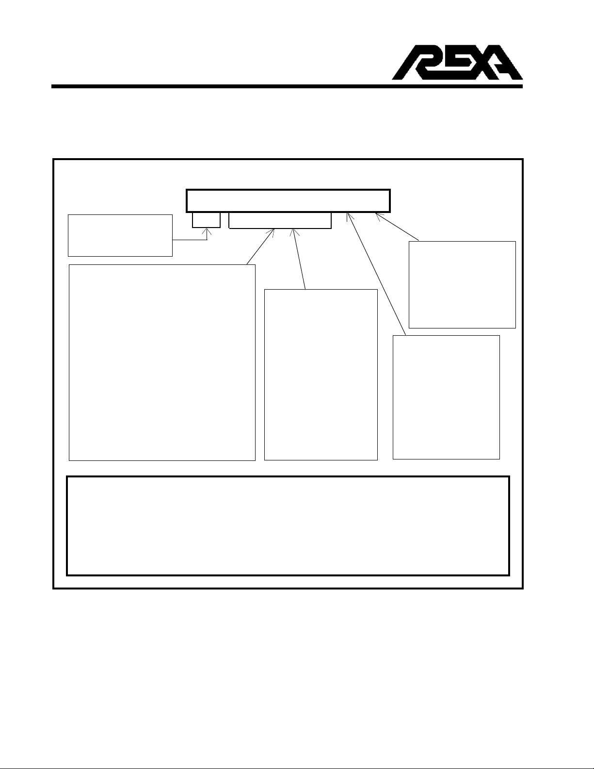
Model Number
_ _ _ _ _ – _ _ – _ – _
Spring Fail Option
(Upon Power Loss)
P: None - Lock in Place
U: Universal (Rotary)
E: Extend (Linear)
R: Retract (Linear)
A: Accumulator Failure
R Series - Xpac Rotary
L Series - Xpac Linear
D Series - Xpac Drives
Torque – Rotation
Thrust – Stroke
Series
Power Modules
B: Single B
C: Single C
½D: Single ½D
D: Single D
2D: Two D Manifold
2C: Two C Manifold
2B: Two B Manifold
P9: Booster Pump, 9
Rotary
Drive
L SERIES
Thrust Rated Strokes
(lbs) (in inches)
2,000 –.75, –2, –4 –6, –8, –11
4,000 –.75, –2, –4
5,000 –.75, –2, –4, –6, –8, –11, –16, –22
10,000 –.75, –2, –4, –6, –8, –11, –16, –22
15,000 –.75, –2, –4, –6, –8, –11, –16, –22
20,000 –.75, –2, –4, –6, –8, –11, –16, –22
30,000 –.75, –2, –4, –6, –8, –11, –16, –22
40,000 –.75, –2, –4, –6, –8, –11, –16, –22
50,000 –.75, –2, –4, –6, –8, –11, –16, –22
60,000 –.75, –2, –4, –6, –8, –11, –16, –22
80,000 –.75, –2, –4, –6, –8, –11, –16, –22
120,000 –.75, –2, –4, –6, –8, –11, –16, –22
custom
For Example: L4000-4-C-P
A linear series Xpac with 4000 lbs of thrust and C size Power Module. Lock in position
upon loss of power. Any stroke is adjustable up to 4 inches.
R2500-90-B-U
A rotary series Xpac with 2500 inch-lbs of torque and B size Power Module. Spring failure
upon loss of power. Any rotation is adjustable up to 90 degrees.
R or D SERIES
Torque Rotation
(inch-lbs) (degrees)
600 –90, –120
1,200 –90, –120
2,500 –90, –120
5,000 –90, –120
10,000 –90, –120
20,000 –90, –120
50,000 –90, –120
100,000 –90, –120
200,000 –90, –120
400,000 –90, –120
custom
Linear

REXA
Electraulic Actuators & Drives
Xpac Installation Manual -- Version 5.1 (5/08)
3
1 THEORY OF OPERATION
Overview
The REXA Xpac is a microprocessor controlled, self contained,
Electraulic (electro-hydraulic) actuator or drive designed specifi-
cally for modulating service. Hydraulic, electronic and mechanical
technologies are combined to achieve the state of the art in actuator
design.
The patented Flow Match System is simply described as a highly ef-
ficient method of pumping hydraulic fluid (motor oil Castrol Syntec
SAE 5W-50) from one side of a double acting cylinder to the other.
Once the correct position is reached, the motor shuts off. Power is
not required to maintain actuator position. The hydraulics are con-
trolled by a dedicated microprocessor contained within the control
enclosure. Software designed for the Xpac allows the user to set
actuator operation parameters.
The Xpac consists of two major components, the actuator (cylinder,
feedback and Electraulic power module) and the control enclosure.
The actuator is installed on the driven device, while the enclosure is
remotely mounted. Connecting them are the module cable and the
feedback cable.
Figure 1.A Xpac
Control Signal
4-20 mA
Other Analog and
Pulse Available
Power
Module
Motor
Programming
Keypad
Feedback
Sensor
Actuator
Electric Power
120 Vac,
220 Vac, 440 Vac,
48 Vdc, 24 Vdc
Control
Enclosure
8 8 8 8 8
E

Xpac Installation Manual -- Version 5.1 (5/08)
4REXA
Electraulic Actuators & Drives
1.1 Actuator
The heart of the actuator is the Electraulic Power Module. Consisting
of a motor, gear pump, flow match valve (FMV), make-up oil reser-
voir, heater and bypass solenoid (spring fail units only), the Power
Module delivers oil at a nominal 2000 psi to a hydraulic cylinder.
Four different size modules, B, C, ½D and D, are available. The
functional difference between the sizes is strictly pumping volume
and thus, the maximum stroking speed of an actuator. The only vis-
ible difference is the motor.
Figure 1.B
There are three types of hydraulic cylinders. On smaller size linear
actuators (thrust of 10,000 lbs or less and strokes of 6 inches or less),
the cylinder is manufactured from a solid block of aluminum. Larger
size linear cylinders are made of a fabricated tie-rod construction.
The third type, used on rotary and drive units, is a rack and pinion
rotary design. An inherent requirement with the Flow Match System
is equal displaced oil volumes on both sides of the cylinder. This
allows oil movement without an active reservoir. Double rod con-
struction on linear units and opposed cylinders on the rotary units
meet this criteria.
To provide position information, a feedback assembly consisting of
a resistive film potentiometer and a transmitter (4-20 mA) circuit
board is used. The feedback assembly is sealed in a NEMA 4X area
and mounted within or adjacent to the cylinders. The connection of
the potentiometer is by direct mechanical means to the output shafts.
Shock loading and vibration has no effect on readings and lost mo-
tion in the rotary rack and pinion is eliminated.

REXA
Electraulic Actuators & Drives
Xpac Installation Manual -- Version 5.1 (5/08)
5
1.2 Control Enclosure
The control enclosure contains the position control processor (PCP),
power supplies, fuses and filters, motor drivers and a termination
area. The PCP consists of an 8-bit, 80C52 microprocessor, a 32
Kbyte EEPROM memory for program storage, a 2 Kbyte EEPROM
memory for data storage, a 12-bit A/D converter, and a 3-button/5-
digit display user interface. The PCP also provides two connectors
which accept optional I/O interface boards.
The power supplies vary according to the type and quantity of power
modules. Common to all types is the logic power supply which pro-
vides +5, +15, -15 VDC to the PCP and +15 VDC to the feedback
assembly. For actuators built with B size power modules, the control
enclosure includes an unregulated, 53 VDC power supply for the
motor. For C, ½D and D size power modules, the power supplies
are built into the motor drivers.
The control enclosure includes one motor driver for each power
module. The motor driver converts the low power logic signals from
the PCP into high voltage, high current motor power to the stepper
motor (B or C) or servo-motor (½D or D).
1.3 Menu Calibration
The PCP is calibrated in the Setup mode by a simple routine. Speed,
stroke, deadband and control signal are some of the parameters that
can be configured by using the three button keypad and the display.
Programmed parameters are retained in a permanent memory. For
unusual or difficult applications, more sophisticated control capabili-
ties
such as flow
characterization and water hammer suppression (two
speed) are available. Access to the Setup mode can be restricted by
a passcode.
1.4 Operational Summary
By using the stroke and signal ranges set during calibration, the PCP
converts the incoming control signal into a target position. The cur-
rent position is determined through the active feedback assembly
mounted on the actuator. The difference between the target and
current position is the error.

Xpac Installation Manual -- Version 5.1 (5/08)
6REXA
Electraulic Actuators & Drives
If the error exceeds the deadband (user set), then the PCP will initiate
corrective action by starting the motor.
A reversible hydraulic pump is driven by the motor. The pump can
pressurize either side of a double acting cylinder through one of two
Flow Matching Valves, FMV-1 and FMV-2. Each FMV is comprised
of a ported spool with an integral pilot operated check valve. The
ports of both FMVs are sized exactly the same.
To move the piston to the left, the pump turns in the direction to
pressurize FMV-2 through port A. The spool in FMV-2 becomes
unbalanced by the pressure differential and moves to the left, lifting
its check valve, opening port D to port B and port A to port E.
High pressure fluid flows through Port E to the right side chamber of
the cylinder. Since the hydraulic circuit is closed, the same amount
of oil that flows into the right side of the piston must be extracted
from the left side. This oil flows through the open check valve of
FMV-2 and into pump suction.
By rotating the pump in the opposite direction, the FMVs operate in
reverse to move the cylinder rod to the right. When the pump stops,
both check valves close. The hydraulic oil is locked within the cyl-
inder. Motor operation is not required to maintain position.
Figure 1.C Hydraulic Schematic

REXA
Electraulic Actuators & Drives
Xpac Installation Manual -- Version 5.1 (5/08)
7
1.5 Optional Equipment (see Appendices)
The Xpac is available with a substantial list of optional equipment.
Most items can be field retrofitted. Consult your local sales repre-
sentative for details.
1.5.1 Position Transmitter (see Appendix C.1)
The position transmitter provides a loop powered two-wire 4-20 mA
signal that is proportional to actuator position. The transmitter's
output is optically isolated from the electronics. Both an active and
passive transmitter are available. A passive position transmitter is
similar to other two-wire transmitters in that an external DC power
source is required. An active two-wire transmitter with its own 24
VDC power supply is available.
1.5.2 Manual Override (see Appendix C.2)
A declutchable handwheel connects to the outboard end of the mo-
tor shaft. Since the handwheel utilizes the same hydraulic circuit as
the motor, the required torque is low. On actuators with high thrust
or torque or long strokes, a 5/16" hex drill drive may be substituted
for the handwheel or a 5:1 geared hand crank on a separate power
module is available.
1.5.3 Limit Switches (see Appendix C.3)
Limit switches are either yoke mounted or PCP mounted. Yoke
mounted switches are activated by the actuator shaft and function
independently. The PCP mounted switches are activated electrically
and include an alarm relay.
1.5.4 Alarm Relay (see Appendix C.4)
The PCP is able to perform various diagnostic functions. If the ac-
tuator cannot follow the control signal, the alarm relay will change
state to provide remote indication. The alarm relay is included on
the position transmitter and PCP mounted limit switches.
1.5.5 Surge Control (see Appendix S)
By utilizing a spring, solenoid and solid state relay, the Xpac can
provide very high speed motion in one direction. The position can
be to any intermediate point or strictly to the end (trip).
The alarm relay will change state upon
power failure or removing the unit
from automatic (Auto).

Xpac Installation Manual -- Version 5.1 (5/08)
8REXA
Electraulic Actuators & Drives
1.5.6 Pulse Input (see Appendix P)
In place of or in conjunction with the normal analog control signal,
pulse or contact signals can provide control input to the actuator.
Three or four wire, 24 to 120 volts, AC or DC, signals can be used.
1.5.7 Auxiliary Controls - External (see Appendix
C.5.1)
To limit access to the control enclosure, a window (to view the position
display) and external push-buttons can be provided. The push-buttons
will only allow manual override of actuator position.
1.5.8 Auxiliary Controls - Remote (see Appendix C.5.2)
Manual operation of the actuator from a remote location is available
with the remote control option. Three contact inputs are required:
auto/remote (two position), open (momentary contact), and close
(momentary contact). Power for the switches are supplied by the
control enclosure. Manual stations are available from REXA.
1.5.9 Spring Failure
While still maintaining the control capability available in the stan-
dard Fail in Place version, the spring failure provides a high degree
of safety. The spring is continuously engaged and is compressed or
expanded during operation. A bypass valve which connects both
sides of the hydraulic cylinder is kept closed by a normally open
(NO) solenoid.
1.5.10 Accumulator Failure (see Appendix G)
Use of an accumulator eliminates the need to "oversize" the actuator
as with a spring fail unit. The accumulator puts no load on the power
module during normal operation so actuator size is reduced. REXA's
unique accumulator technology uses the power module to recharge
the accumulator, thus eliminating the need for a separate re-charge
pump and associated plumbing. This feature allows all components
of the accumulator system to be located on the actuator.
1.5.11 Stem Boot
Linear actuators installed at locations containing airborne particles
may be subjected to accelerated seal wear. The normal motion of the
stem can transport contaminants through the seals causing damage. A
stem boot over the shaft offers protection from the environment.

REXA
Electraulic Actuators & Drives
Xpac Installation Manual -- Version 5.1 (5/08)
9
1.5.12 Split Clamps
On linear actuators mounted at unusual angles or with reduced ac-
cessibility, a split clamp connection between the actuator and driven
device is available. The difficulties of stem rotation, shaft insertion
and jam nuts are eliminated.

Xpac Installation Manual -- Version 5.1 (5/08)
10 REXA
Electraulic Actuators & Drives
2 DELIVERY
2.1 Receipt
Inspect the crate and make note of any physical damage. If severe
damage is present, then consideration should be given to rejecting the
shipment and contacting the shipping company concerning in-transit
damage claims. REXA makes every effort to properly package the
product so that it is shipped and received without damage.
2.2 Storage
If the actuator and control enclosure are not immediately installed,
provisions for storage must be made. The equipment should not be
removed from the original containers. The ambient environment
must be:
✔ Clean—no airborne particles or contaminants
✔ Non
Corrosive—minute quantities of gases can concentrate
in a confined area
✔ Dry—relative humidity must be sufficiently low to prevent
moisture condensation on chilled metal components
✔ Temperature—recommended storage temperature is be-
tween 10°F (–12°C) and 120°F (50°C)
2.3 Unpacking
The REXA Xpac actuator is shipped completely filled with oil and
ready to be installed. It has been operated, tested and thoroughly
inspected. After removing the actuator from the packaging, inspect
it for any signs of mechanical damage that may have occurred during
shipping. Immediately report any damage to the factory.
Compare the contents to the packing list included with every shipment.
Immediately report any discrepancies to the factory.

REXA
Electraulic Actuators & Drives
Xpac Installation Manual -- Version 5.1 (5/08)
11
3 OIL
The Xpac is a sealed, self-contained Electraulic actuator. During
normal operation, the hydraulic oil is pumped from one side of a
double acting cylinder to the other. An oil reservoir which provides
a source of “make-up” oil is an integral component. Any external
signs of a major oil leak may be indicative of damage to the Xpac
and should be investigated.
The oil reservoir is sealed and spring loaded. Oil degradation from
moisture or other external contaminates should not occur. Reservoir
operation is unaffected by actuator orientation.
3.1 Level Check
There is a visual indicator on the side of the reservoir housing to
show the oil level. The indicator is a red-colored rod which should be
exposed between ¼ to ½ inches. The normal fill position is shown by
a scribe mark around the rod. If the indicator protrudes less than ¼
inch beyond the housing, then the actuator should be filled with oil.
3.2 Filling
The underside of the Electraulic power module is provided with a
standard pneumatic style Schrader fitting. The mating half can be
obtained at any auto parts dealer. To fill the Xpac with oil, use a
lever operated grease gun. Install the fitting on the grease gun. Fill
the grease gun with clean Castrol Syntec SAE 5W-50 motor oil. An
unusual application may require a different oil (refer to the actuator
serial plate).
Pump the grease gun a few times to purge any air and hold the fitting
on the oil fill valve of the Xpac. Pump oil into the reservoir. While
pumping, observe the oil indicator. When the scribe marker or ½
inch is exposed, the reservoir is filled. A 10 micron filter screens the
oil before it enters the reservoir.
The actuator does not have to be taken
out of service when filling with oil.
All air must be purged from the grease
gun before attempting to add oil.

Xpac Installation Manual -- Version 5.1 (5/08)
12 REXA
Electraulic Actuators & Drives
A reservoir relief valve is installed on the top of the power module
on fail in place units and next to the oil fill valve on spring failure
units. If oil flows from this valve when filling, the reservoir has been
overfilled. No damage will occur (see section 3.3). Wipe the unit
down and proceed. The relief valve will re-seat.
3.3 Oil Weeping (Thermal Expansion)
When the reservoir is overfilled, an increase in ambient temperature
may cause a small amount of oil to weep from the relief valve. The
actuator is a closed hydraulic system and an increase in oil volume
must be purged. This action is a normal occurrence. If the tempera-
ture is lowered, the reservoir indicator will retract as the oil volume
decreases. Overfilling the reservoir at this time will begin the weep
cycle again. Review section 3.2 for the correct filling procedure.
On large oil volume actuators, a
separate auxiliary reservoir may be
required. This reservoir is hydrauli-
cally linked to the internal reservoir
and they function as one volume.
RELIEF VALVES
Fail in Place
Spring Fail
On spring fail units the pressure relief
valve can be found coupled with the oil
fill valve.
Table of contents
Other Koso Controllers manuals
Popular Controllers manuals by other brands

VeriFone
VeriFone Commander Site Controller Software installation guide

Unigas
Unigas G258A Manual of installation - use - maintenance

Siemens
Siemens OpenAir GLB Series manual

SOMFY
SOMFY animeo Installation and operating instructions

Atmel
Atmel XMEGA B user manual

Kilews
Kilews SKP-32BC-60W Operation and maintenance manual

GARDASOFT
GARDASOFT TR-HT2 Series user manual

Aruba Networks
Aruba Networks 7210 installation guide

Advantage
Advantage MicroTron installation manual

PROSPERITY GROUP
PROSPERITY GROUP TRAXON e:cue 3 mx INFORMATION FOR USE

heat-timer
heat-timer HTC Installation and operation manual

TIVAL
TIVAL FF4 operating instructions