manuals.online logo
Brands
  1. Home
  2. •
  3. Brands
  4. •
  5. Controlli
  6. •
  7. Controllers
  8. •
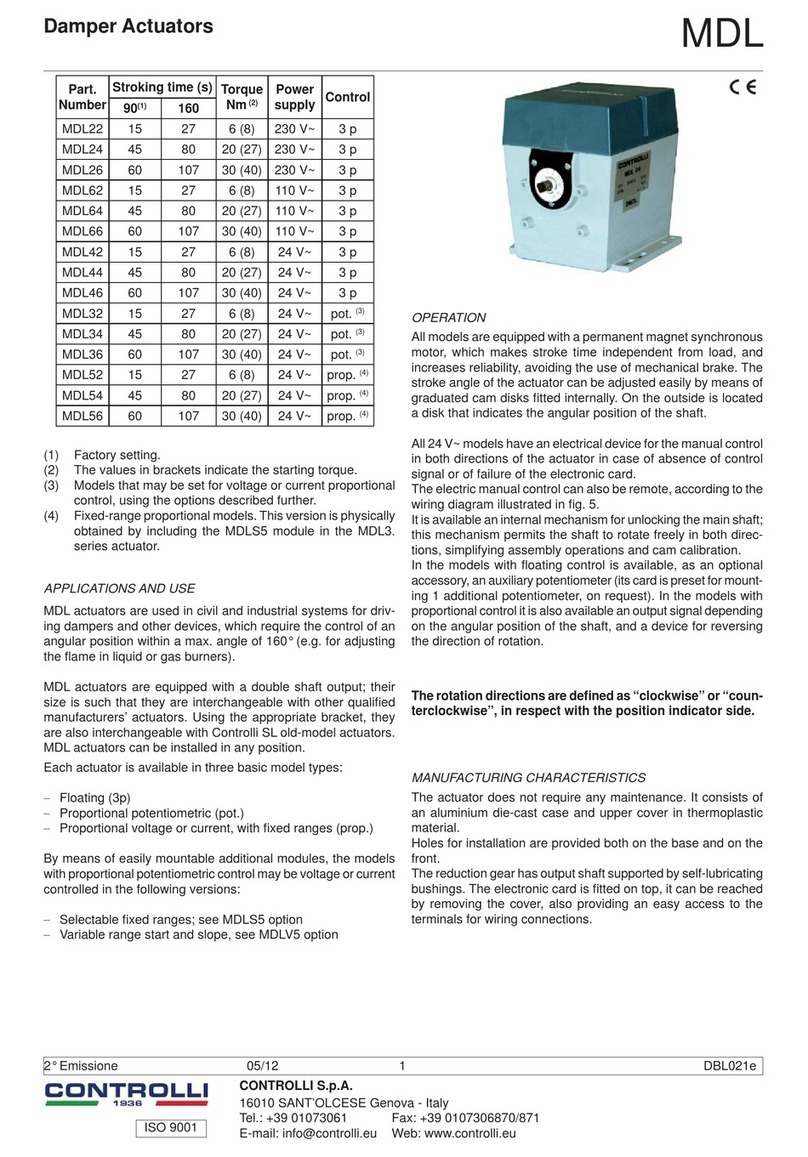
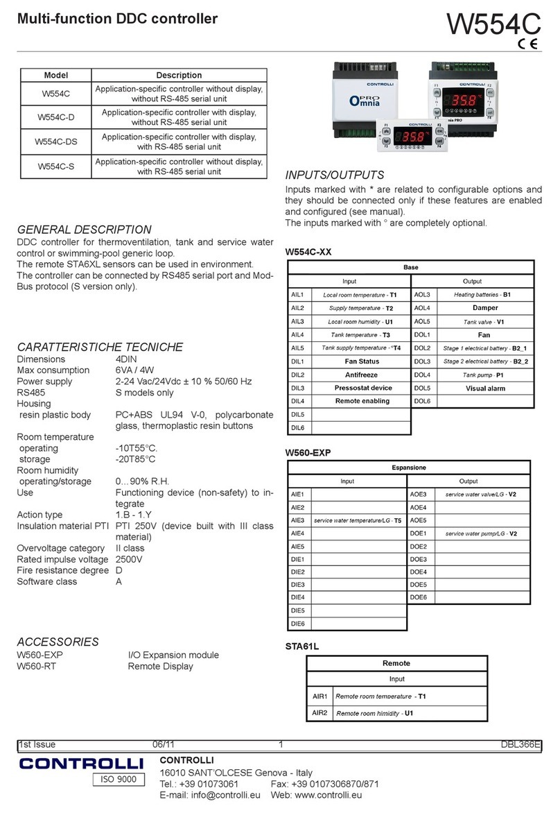
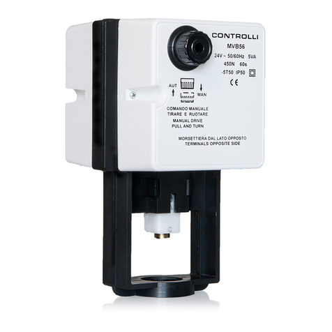
  9. Controlli MVH56EX User manual

Controlli MVH56EX User manual

ISO 9001
CONTROLLI S.p.A.
16010 SANT’OLCESE Genova - Italy
Tel.: +39 01073061 Fax: +39 0107306870/871
E-mail: [email protected] Web: www.controlli.eu
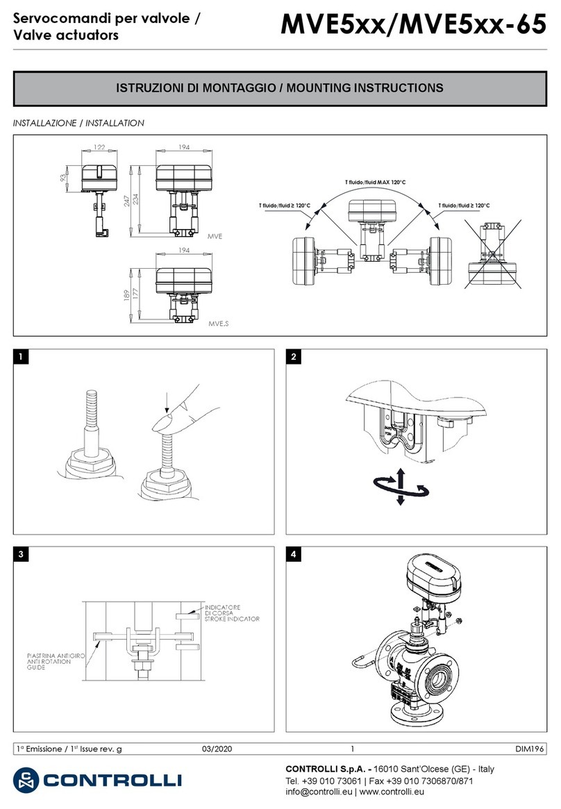
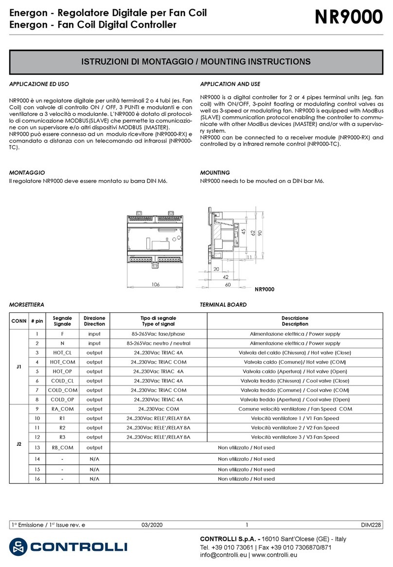
ISTRUZIONI DI MONTAGGIO / MOUNTING INSTRUCTIONS
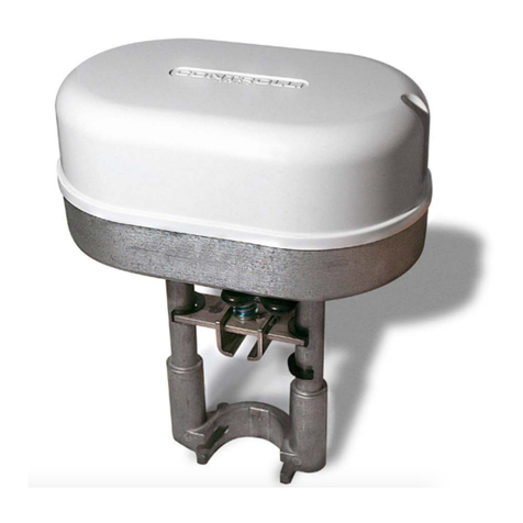
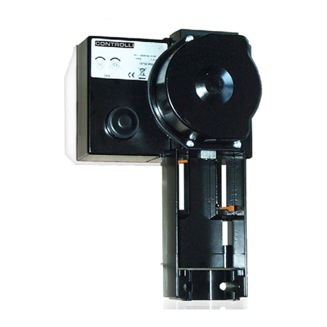
Servocomandi per valvole con dispositivo di ritorno in emergenza/
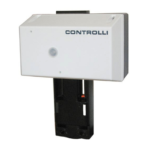
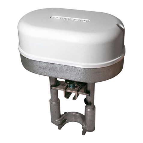
Valve actuators with emergency fail safe function MVH56EX
1° Emissione / 1st Issue 05/17 1 DIM262
MVH56EA
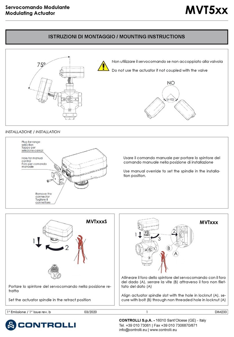
INSTALLAZIONE / INSTALLATION
Il uido all’interno della valvola può essere molto caldo. Prima di
rimuovere il servocomando o aprire la valvola, assicurarsi che il
uido sia isolato e togliere pressione alla valvola. L’operazione
dovrebbe essere eseguita da personale esperto.
Attenzione: Non utilizzare il servocomando disaccoppiato
dalla valvola.
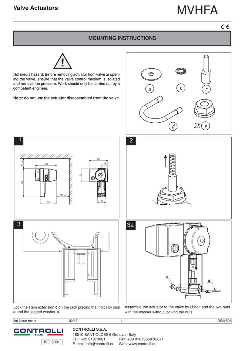
Hot media hazard. Before removing actuator from valve or open-
ing the valve, ensure that the valve control medium is isolated
and remove the pressure. Work should only be carried out by a
competent engineer.
Note: do not use the actuator disassembled from the valve.
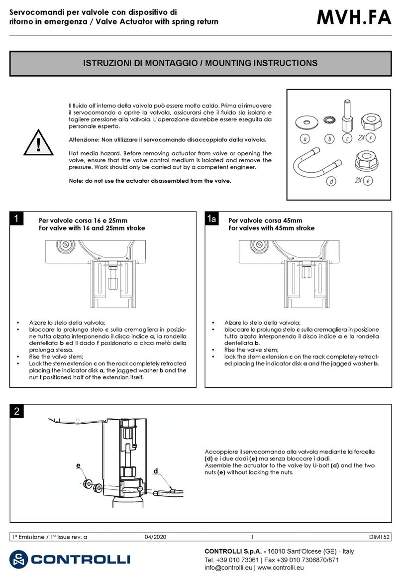
• Alzare lo stelo della valvola;
• bloccare la prolunga stelo c sulla cremagliera in posizio-
ne tutta alzata interponendo il disco indice a, la rondella
dentellata b ed il dado f posizionato a circa metà della
prolunga stessa.
• Rise the valve stem;
• Lock the stem extension c on the rack completely re-
tracted placing the indicator disk a, the jagged washer
b and the nut f positioned half of the extension itself.
• Alzare lo stelo della valvola;
• bloccare la prolunga stelo c sulla cremagliera in po-
sizione tutta alzata interponendo il disco indice a e la
rondella dentellata b.
• Rise the valve stem;
• lock the stem extension c on the rack completely
retracted placing the indicator disk a and the jagged
washer b.
Per valvole corsa 16 e 25mm
For valve with 16 and 25mm stroke Per valvole corsa 45mm
For valves with 45mm stroke
Accoppiare il servocomando alla valvola mediante la forcella
(d) e i due dadi (e) ma senza bloccare i dadi.
Assemble the actuator to the valve by U-bolt (d) and the two
nuts (e) without locking the nuts.
ISO 9001
MVH56EC
1
Abbassare lo stelo della valvola. Bloccare la prolunga stelo c
sulla cremagliera in posizione tutta abbassata interponendo il
disco indice a, la rondella dentellata b ed il dado f posizionato
a circa metà della prolunga stessa.
Lower the valve stem. Lock the stem extension c on the rack
completely extended placing the indicator disk a, the jagged
washer b and the nut f positioned half of the extension itself.
1a
Abbassare lo stelo della valvola. Bloccare la prolunga stelo c
sulla cremagliera in posizione tutta abbassata interponendo
il disco indice a e la rondella dentellata b.
Lower the valve stem. Lock the stem extension c on the rack
completely extended placing the indicator disk a and the
jagged washer b.
Per valvole corsa 16 e 25mm Per valvole corsa 45mm
• Togliere il coperchietto
• Ruotare il perno in senso antiorario di 1/2 giro e bloccar-
lo incastrando una chiave a forchetta come indicato in
gura.
• Remove the cover
• Rotate the pivot 1/2 turn counter-clockwise and lock it by
a spanner as shown in the picture.
2
- Sollevare lo stelo della valvola.
- Togliere il coperchietto e ruotare il perno in senso orario facendo fuoriuscire la
cremagliera di quanto basta per accoppiarla con lo stelo della valvola; il perno
può essere bloccato incastrando una chiave a forchetta come indicato in gura
- Ruotare il servocomando per avvitare la prolunga sullo stelo della valvola, quindi
bloccarla stringendo il dado presente sullo stelo.
- Stringere i due dadi sulla forcella per bloccare il servocomando.
- Togliere la chiave dal perno e montare il coperchietto.
- Raise the valve stem.
- Remove the cover and rotate the pivot clockwise so that the rack comes out for
assembling it with the valve stem; the pivot can be locked by a spanner as shown
in the picture.
- Rotate the actuator to screw the extension on the valve stem, so lock it tightening
the nut on the stem.
- Tighten the two nuts on the U-bolt to lock the actuator.
- Remove the key from the pivot and mount the small cap.
1° Emissione / 1st Issue 05/17 2 DIM262
ISO 9001
MORSETTIERA / TERMINAL BLOCK
SCHEMA DI COLLEGAMENTO / WIRING DIAGRAM
N.B.: Non esercitare una pressione eccessiva quando si inse-
risce la morsettiera per evitare che la essione del PCB possa
danneggiare i componenti elettronici sulla scheda.
Note: To avoid damages to electronic components caused by
the PCB bending, do not press too much while xing the termi-
nal block.
L1 / Ln
0 V
24Vac/dc
U
Y
M
Y1 Y2
Avvitare la prolunga stelo sullo stelo della valvola no a che la
gola presente alla base del servocomando coincida con quella
presente sulla valvola, quindi bloccare la prolunga stringendo
il dado presente sullo stelo. Nel caso in cui, ad avvitamento
completato, le due gole non coincidano ancora, ruotare il perno
in senso antiorario nché non coincideranno.
Screw the extension on the valve stem until the groove on the
actuator base coincides with the one on the valve, then lock
the extension tightening the nut on the stem. In case the two
bases do still not coincide, rotate the pivot until it happens.
Accoppiare il servocomando alla valvola mediante la forcella
(d) e bloccando i due dadi (e).
Assemble the actuator to the valve by U-bolt (d) and locking
the two nuts (e).
3
4
1° Emissione / 1st Issue 05/17 3 DIM262
ISO 9001
Label Description Function
Min Wire
Size (#
AWG)
Max wire
Length
L1 24Vac/Vdc Power
Supply
1.5mm2
(AWG16) 75m
Ln 0V
Y0..10Vdc Modulating
Control Input
0.5mm2
(AWG20) 200m
M0V (Common)
Y1 Open Floating
Control Input
0.5mm2
(AWG20) 200m
Y2 Close
V+ 16Vdc Voltage
Output (max
25mA)
0.5mm2
(AWG20) 200m
M0V (Common)
U 2÷10Vdc Feedback
Output
Signal
0.5mm2
(AWG20) 200m
M0V (Common)
Etichetta Descrizione Funzione
Sezione min.
del cavo
(# AWG)
Lunghezza
massima
del cavo
L1 24Vac/Vdc Alim. 1.5mm2
(AWG16) 75m
Ln 0V
Y0..10Vdc Ingresso
comando mo-
dulante
0.5mm2
(AWG20) 200m
M0V (Comune)
Y1 Apertura Ingresso co-
mando ottante
0.5mm2
(AWG20) 200m
Y2 Chiusura
V+ 16Vdc uscita in tensio-
ne (max 25mA)
0.5mm2
(AWG20) 200m
M0V (Comune)
U 2÷10Vdc uscita segnale
di feedback
0.5mm2
(AWG20) 200m
M0V (Comune)
Corrispondenza morsetti rispetto alle altre linee di prodotto at-
tuatori Controlli.
Terminals correspondence with respect to other Controlli actua-
tors models.
K1 K2 KC1
K1 K2 KC1
End point
position
End point
position
DMVE
RELE' DI CHIUSURA
RELE' DI APERTURA
K3 K4 KC2
Posizione
di fine corsa
Posizione
di fine corsa
K3 K4 KC2
OPENING RELAY
CLOSING RELAY
DMVE
1° Emissione / 1st Issue 05/17 4 DIM262
ISO 9001
(*) I servocomandi MVH56Ex sono alimentati da un raddrizzatore a semi-onda integrato sulla scheda, per cui non deve essere
impiegato un trasformatore usato da altri dispositivi che utilizzino un raddrizzatore a onde complete non isolato.
(*) MVH56Ex contain a half-wave rectier power supply. They must not be powered with transformers that are used to power other
devices using not isolated full-wave rectier power supply.
N.B. I segnali M e Ln sono connessi
internamente.
N.B. Signals M and Ln are internally
connected.
Controllore(*)
Comando flottante a 3 punti
(Connessione sink)
0V
Y2
Ln
MVH56Ex
Y1
APRI
24Vac/24Vdc
L1
CHIUDI
Comando flottante a 3 punti
(Connessione source)
24Vac
0V
Controllore(*)
APRI
CHIUDI
L1
Y1
Y2
MVH56Ex
Ln
COMANDO +
COMANDO -
Controllore (*)
MVH56Ex
24Vac/24Vdc
0V
Comando modulante (0-10Vcc)
L1
Ln
Y
M
Controller(*)
3-point floating control
(sink connection)
0V
Y2
Ln
MVH56Ex
Y1
OPEN
24Vac/24Vdc
L1
CLOSE
3-point floating control
(source connection)
24Vac
0V
Controller(*)
OPEN
CLOSE
MVH56Ex
L1
Ln
Y1
Y2
COMMAND +
COMMAND -
Controller (*)
MVH56Ex
24Vac/24Vdc
0V
Modulating control (0-10Vcc)
L1
Ln
Y
M
1° Emissione / 1st Issue 05/17 5 DIM262
ISO 9001
REGOLAZIONE DEGLI INTERRUTTORI DIP E DEL JUMPER
Impostare gli interruttori DIP secondo
le seguenti tabelle. Per fare in modo
che le impostazioni vengano recepite
è necessario o rimuovere e riapplicare
l’alimentazione oppure agire sulla ma-
nopola del comando manuale.
Set the DIP switches according to the
tables here below. In order to be sure
that any modication has been accep-
ted by the actuator, power down and
power up it again or act on the manual
operation handle to be sure that set-
tings will be recognized.
Impostazioni di fabbrica
DIP SWITCHES AND JUMPER SETTINGS
Factory settings
Dip
switch OFF ON
1
Azione Diretta Azione Inversa
2
Modulante (MOD) (ingresso tra Y [+] e M [-]) 3 punti (INC) ( Y1 apre, Y2 chiude il contatto può essere prelevato
indifferentemente da L1 o LN se alimentato in Vac; se alimentato
in Vdc è necessario prelevare il contatto da Ln)
3-Selezione sequenza con range deniti dal DIP n. 5
4Controllo modulante 0-10Vdc
(solo con DIP n. 2 OFF)
Controllo modulante 2-10Vdc
(solo con DIP nr. 2 OFF)
5
Controllo modulante sequenziale 0-5Vdc con DIP n. 4 OFF
Controllo modulante sequenziale 2-6Vdc con DIP n.4 ON
(solo con DIP n. 3 ON)
Controllo modulante sequenziale 5-10Vdc con DIP n. 4 OFF
Controllo modulante sequenziale 6-10Vdc con DIP n. 4 ON
(solo con DIP n. 3 ON)
6Controllo in tensione Vac
(ingresso tra Y [+] e M [-])
Controllo in corrente 4-20mA
(ingresso tra Y [+] e M [-]). Per questa funzione il DIP n. 4 deve
essere impostato su ON
7
Apprendimento della corsa automatico: l’acquisizione del
valore della corsa viene eseguito automaticamente ogni qual
volta l’attuatore arriva allo scontro meccanico della valvola e
vi si ferma per almeno 10s
Apprendimento della corsa manuale: l’acquisizione del valore della
corsa si effettua muovendo il DIP da OFF a ON; se l’interruttore
viene lasciato in ON, l’attuatore non aggiornerà la corsa acquisita
anche in presenza di scontro inatteso
U = 2V
U = 2V
U = 10V
U = 10V
U= feedback
U= feedback
U = 10V
U = 10V
U = 2V
U = 2V
U= feedback
U= feedback
Dip
switch OFF ON
1
Direct Action Reverse Action
2
Modulating Control (MOD) (Input between Y [+] and M [-]) 3 point oating (INC) ( Y1 open-extend , Y2 close-retract
connected L1 or Ln if powered in Vacd; if powered in Vdc
connected necessarily to Ln )
3-Selection of sequence mode, control range dened by SW 5
4Modulating Control 0-10Vdc
(DIP n. 2 OFF only)
Modulating Control 2-10Vdc
(DIP n. 2 OFF only)
5
Sequence Control 0-5Vdc with DIP n. 4 OFF only
Sequence Control 2-6Vdc with DIP n. 4 ON only
(DIP n. 3 ON only)
Sequence Control 5-10Vdc with DIP n. 4 OFF only
Sequence Control 6-10Vdc with DIP n. 4 ON only
(DIP n. 3 ON only)
6Voltage Input Signal
(input between Y [+] and M [-])
Current Input Signal 4-20mA
(input between Y [+] and M [-]). In this case DIP n. 4 must be set
to ON.
7
Automatic Calibration: the actuator updates the stroke range
every time an unexpected mechanical stop is detected for at
least 10s
Manual Calibration: the actutor calibration is started moving the
DIP from OFF to ON; if the DIP is left in ON the actuator will never
update the calibrated stroke value even when an unexpected
endpoint is detected
Y1
Y1
Y2
Y2
1° Emissione / 1st Issue 05/17 6 DIM262
ISO 9001
DIAGNOSTICA - FUNZIONE ALLARMI (VIA LED) / DIAGNOSTIC - ALARM FUNCTIONS (VIA LED)
N° Comportamento
LED ERRORE UTILIZZO
ATTUATORE
Comportamento dell’attuatore
Possibile
problema
Procedura di
ripristino
Apprendimento corsa
automatico
(DIP n. 7 OFF)
Apprendimento corsa
manuale
(DIP n. 7 ON)
1ROSSO FISSO
Corsa
Valvola
minore di
5mm
Calibrazione
(manuale o prima
istallazione)
L’attuatore spinge e
tira 5 volte (scontro
inatteso) per tentare di
rimuovere l’eventuale
ostacolo. Segnala
allarme (LED ROSSO
ON) dopo i 5 tentativi .
Il servocomando NON
apprende la nuova
corsa dopo 10s (Range
errato)
L’attuatore spinge e
tira 2 volte agli estremi
(fase di calibrazione).
Segnala allarme (LED
ROSSO ON) e si
riporta in posizione
iniziale e non risponde
al comando
Valvola non
adatta (corsa
inferiore a
5mm) oppure
accoppiamento
incorretto.
Spegnere
l’attuatore e
ripetere la fase
di calibrazione
2ROSSO FISSO
Corsa
Valvola
maggiore di
60mm
Calibrazione
(manuale o prima
istallazione)
L’attuatore esce dal
range massimo di 60mm
e va verso la nuova
posizione segnalando
allarme (LED ROSSO
ON). Il servocomando
NON apprende la nuova
corsa dopo 10s (Range
errato)
L’attuatore spinge e
tira 2 volte agli estremi
(fase di calibrazione).
Segnala allarme (LED
ROSSO ON) e si
riporta in posizione
iniziale e non risponde
al comando
Perdita del
linkage o valvola
non adatta (corsa
superiore a
60mm)
Spegnere
l’attuatore e
ripetere la fase
di calibrazione
3
ROSSO
LAMPEGGIANTE
VELOCE + VERDE
FISSO
Scontro
inatteso
entro il
range
di corsa
calcolato
IN
FUNZIONAMENTO
NORMALE
L’attuatore verica la
condizione di stallo
per 5 volte. Al termine
dei tentativi segnala
anomalia (LED ROSSO
ON).Il servocomando
apprende la nuova
corsa dopo 10s
L’attuatore verica
la condizione di
stallo per 5 volte. Al
termine dei tentativi
segnala anomalia
(LED ROSSO ON).Il
servocomando NON
apprende la nuova
corsa, ma dopo 60s
ripete i tentativi per
vericare le condizioni
di blocco
Blocco della
valvola o valvola
non adatta
Inversione
del segnale di
comando
4
ROSSO
LAMPEGGIANTE
VELOCE + VERDE
FISSO
Corsa
superiore
al range
di corsa
calcolato.
IN
FUNZIONAMENTO
NORMALE
L’attuatore si porta
verso la nuova
posizione massima
con bassa velocità
segnalando anomalia
(LED ROSSO e VERDE
ON).Il servocomando
apprende la nuova
corsa dopo 10s
L’attuatore si porta
verso la nuova
posizione massima
con bassa velocità
segnalando anomalia
(LED ROSSO e
VERDE ON).Il
servocomando NON
apprende la nuova
corsa
Perdita del
linkage o valvole
danneggiate
Inversione
del segnale di
comando
5
ROSSO
LAMPEGGIANTE
LENTO
Bassa
Tensione
IN
FUNZIONAMENTO
NORMALE
L’attuatore continua ad
operare (Prestazioni
non garantite)
L’attuatore continua ad
operare (Prestazioni
non garantite)
1. Incorretto
dimensionamento
del trasformatore Alimentazione
nel range di
funzionamento
2. Alimentazione
instabile
6
ROSSO
LAMPEGGIANTE
LENTO
Alta
Tensione
IN
FUNZIONAMENTO
NORMALE
L’attuatore continua ad
operare (Prestazioni
non garantite)
L’attuatore continua ad
operare (Prestazioni
non garantite)
1. Incorretto
dimensionamento
del trasformatore Alimentazione
nel range di
funzionamento
2. Alimentazione
instabile
1° Emissione / 1st Issue 05/17 7 DIM262
ISO 9001
Sistemi di regolazione automatica per:
condizionamento/riscaldamento/processo termico industriale.
Le caratteristiche contenute in questa pubblicazione possono essere modifi cate senza preavviso
Automatic control systems for:
air conditioning/heating/industrial thermal process.
The performances stated in this sheet can be modifi ed without any prior notice
N° LED
behaviour Error Actuator
use
Actuator Behaviour Typical
trouble
shooting
condition
Reset
procedure
Automatic Calibration
DIP N. 7 OFF
Manual Calibration
DIP N. 7 ON
1RED ON
valve stroke
less than
5mm
Calibration/
rst
installation
The actuator pushes/pulls
5 times (unexpected stall)
trying to remove the possible
obstacle. After 5 tries an alarm
is signalled (RED LED ON)
and the actuator moves to
initial position and does not
respond to control signal.
Stroke value is not updated
because out of range
The actuator pushes/pulls 2
times against endpoint during
calibration. Alarm is signalled
(RED LED ON) and the
actuator moves to the initial
position and then it does not
respond to the control signal
Valve with a
stroke length
lower than
5mm
Remove
power and
power up
again
2RED ON
Stroke
longer than
60mm
Calibration/
rst
installation
The actuator exits the 60 mm
stroke range and it moves
toward the new stroke limit
signalling an anomaly (RED
LED ON). The actuator does
not calibrate the stroke
The actuator pushes/pulls 2
times against endpoint during
calibration. Alarm is signalled
(RED LED ON) and the
actuator moves to the initial
position and then it does not
respond to the control signal
Valve with a
stroke length
longer than
60mm
Remove
power and
power up
again
3
RED
Quick
Blinking
+ GREEN
ON
Unexpected
stall
within the
calibrated
stroke range
normal
operation
The actuator tries 5 times
against the new stall condition
and then after 10s the actuator
updates the new stroke length;
During these 10s RED LED
is ON
The actuator tries 5 times
against the new stall condition.
At the end of the attempts the
fault will be signalled (RED
LED ON). The actuator does
not update the new stroke
length, but after 60s makes
other attempts to verify the
stall condition
Valve stuck
Inverted
control
signal
4
RED
Quick
Blinking
+ GREEN
ON
Stroke
longer than
expected
normal
operation
The actuator moves toward
the new stall condition with
a lower speed; after 10s the
actuator updates the new
stroke value; During these
10s RED LED is ON
The actuator moves toward
the new stall condition with
a lower speed; after 10s the
actuator does not update the
new stroke value
stem
connection
loose
or valve
damaged
Inverted
control
signal
5RED slow
Blinking
Low Power
Voltage
normal
operation
The actuator is still working
but performance cannot be
guaranteed
The actuator is still working
but performance cannot be
guaranteed
1. Wrong
transformer
size Correct
Voltage
Power
2. Unstable
power
6RED slow
Blinking
High Power
Voltage
normal
operation
The actuator is still working
but performance cannot be
guaranteed
The actuator is still working
but performance cannot be
guaranteed
1. Wrong
transformer
size Correct
Voltage
Power
2. Unstable
power
LED STANDARD / STANDARD LEDs
Scheda di controllo Electronic control board
N° Comportamento LED STATO ATTUATORE
1 VERDE FISSO L’attuatore è arrivato all’estremo della corsa
appresa
2VERDE
LAMPEGGIANTE
L’attuatore è arrivato o si sta muovendo verso
un punto intermedio della corsa appresa
3
ROSSO VERDE
LAMPEGGIANTE
ALTERNATO
L’attuatore sta apprendendo la corsa o sta
effettuando il posizionamento iniziale
4ROSSO VERDE
FISSO
Comando manuale inserito, l’attuatore ignora
il segnale di comando.
ATTENZIONE! La scheda è alimentata
5
ROSSO VERDE
LAMPEGGIANTE
SIMULTANEO
L’attuatore è in fase di ritorno in emergenza
N° LEDs behaviour ACTUATOR STATUS
1GREEN ON The actuator arrived at the extreme point of
the stroke
2GREEN BLINKING The actuator is moving or arrived at the
intermediate point of the stroke
3
RED GREEN
BLINKING
ALTERNATING
Calibration or initialization phase
4RED GREEN ON
Manual control enabled, the actuator ignores
the control signal.
ATTENTION! The electronic board is
electrically supplied
5
RED GREEN
BLINKING
SIMULTANEOUS
The actuator is in emergency return phase
1° Emissione / 1st Issue 05/17 8 DIM262
Other Controlli Controllers manuals

Controlli MVE5-65 Series User manual

Controlli

Controlli MVE5-65 Series User manual

Controlli MVB2 Series User manual

Controlli

Controlli MVB2 Series User manual

Controlli MVH56E User manual

Controlli

Controlli MVH56E User manual

Controlli MVH26 User manual

Controlli

Controlli MVH26 User manual

Controlli DG501C User manual

Controlli

Controlli DG501C User manual

Controlli MVT5 Series User manual

Controlli

Controlli MVT5 Series User manual

Controlli Energon User manual

Controlli

Controlli Energon User manual

Controlli MVE2 R-65 Series User manual

Controlli

Controlli MVE2 R-65 Series User manual

Controlli MVT5 Series User manual

Controlli

Controlli MVT5 Series User manual

Controlli NR9000 User manual

Controlli

Controlli NR9000 User manual

Controlli MVE2 Series User manual

Controlli

Controlli MVE2 Series User manual

Controlli MVE2 Series User manual

Controlli

Controlli MVE2 Series User manual

Controlli NR9003 User manual

Controlli

Controlli NR9003 User manual

Controlli MVC503R-MB User manual

Controlli

Controlli MVC503R-MB User manual

Controlli MDL46 User manual

Controlli

Controlli MDL46 User manual

Controlli NR9003 User manual

Controlli

Controlli NR9003 User manual

Controlli Energon NR9001 User manual

Controlli

Controlli Energon NR9001 User manual

Controlli MVHFA User manual

Controlli

Controlli MVHFA User manual

Controlli MVE5 R Series User manual

Controlli

Controlli MVE5 R Series User manual

Controlli MVE5 Series User manual

Controlli

Controlli MVE5 Series User manual

Controlli MVC503R User manual

Controlli

Controlli MVC503R User manual

Controlli MVT203 User manual

Controlli

Controlli MVT203 User manual

Controlli MVE522 User manual

Controlli

Controlli MVE522 User manual

Controlli MVE204S User manual

Controlli

Controlli MVE204S User manual

Popular Controllers manuals by other brands

Lucent Technologies LINEAGE 2000 ECS-6 product manual

Lucent Technologies

Lucent Technologies LINEAGE 2000 ECS-6 product manual

Cisco Flex 7500 Series Deployment guide

Cisco

Cisco Flex 7500 Series Deployment guide

Regin Regio Eddo Instruction

Regin

Regin Regio Eddo Instruction

Brooks SLA7950S Installation and operation manual

Brooks

Brooks SLA7950S Installation and operation manual

Honeywell Pressuretrol L404 Series manual

Honeywell

Honeywell Pressuretrol L404 Series manual

High End Systems High End LCD Controller for Studio Color user manual

High End Systems

High End Systems High End LCD Controller for Studio Color user manual

Honeywell VC6613AJ1000 Mounting instructions

Honeywell

Honeywell VC6613AJ1000 Mounting instructions

AirCom DB110 operating instructions

AirCom

AirCom DB110 operating instructions

Elsner KNX eTR 208 Light/Sunblind Installation and adjustment

Elsner

Elsner KNX eTR 208 Light/Sunblind Installation and adjustment

socorex PROFILLER 435 operating instructions

socorex

socorex PROFILLER 435 operating instructions

V2 TORQ-A manual

V2

V2 TORQ-A manual

Signal SDS Series Operator's manual

Signal

Signal SDS Series Operator's manual

ABB RHDE250 operating instructions

ABB

ABB RHDE250 operating instructions

Emerson EIM HQ Series Installation, operation and maintenance manual

Emerson

Emerson EIM HQ Series Installation, operation and maintenance manual

Lifasa PFCL Elite quick start guide

Lifasa

Lifasa PFCL Elite quick start guide

echoflex ELEDR installation guide

echoflex

echoflex ELEDR installation guide

Softing data FEED edgeGate Quick start up guide

Softing

Softing data FEED edgeGate Quick start up guide

Meggitt VM600 manual

Meggitt

Meggitt VM600 manual

manuals.online logo
manuals.online logoBrands
  • About & Mission
  • Contact us
  • Privacy Policy
  • Terms and Conditions

Copyright 2025 Manuals.Online. All Rights Reserved.