manuals.online logo
Brands
  1. Home
  2. •
  3. Brands
  4. •
  5. KP Electronic Systems
  6. •
  7. Transmitter
  8. •
  9. KP Electronic Systems SIM900 User manual

KP Electronic Systems SIM900 User manual

MATC™
Mini Alarm Transmitter
Cellular
Installation Manual
Web Site: www.kpsystems.com
ISRAEL Office
Email: info@kpsystems.com
Tefen Industrial Park, Tefen 24959
Tel: 972-4-987-3066 Fax: 972-4-987-3692
USA Office:
KP ELECTRONICS INC.
Email: info@kpsystems.com
415 Sargon Way Suite F Horsham PA 19044
Tel: (215) 442-7460 Fax: (215) 442-7461
P.N.: Book 135 Rev New 20/10/2014
This Document refers to MATC™ hardware
MATC™ General Description
MATC™ is a compact long-range, cellular alarm
transmitter. The MATC supports all four GPRS
frequencies: 900/1800 or 850/1900 MHz.
The MATC™ operates in two modes, SMS and
TCP/IP.
When the MATC™ detects an alarm condition at
one, or more of its inputs; an encoded digital alarm
message is prepared. It is then transmitted to the
alarm center, according to the selected mode.
The MATC™ has three sets of connectors: J1, J2,
and the SMA ANT (see Figure 1).
1. J1: A 9-pin contact connector for the
following connections (see Figure 1):
 12 VDC battery (contacts 1 and 2)
 Common Ground (contact 3)
 4 inputs for sensors
(contacts 4 - 7)
 Two serial communication
connections: SI and SO.
Table 1: LEDs description
Purpose No. of
blinks/Color
Description
Net Led
[Led 4-Red]
Fast Blinking Modem is not registered
Slow Blinking The modem is registered
Transmission
Led
[Led3-Red]
1
Will blink each time a
transmission is made in
SMS Mode
Fast Blinking
Will start blinking rapidly
at the beginning of a data
transmission (TCP mode)
Status Indication
Led
[Led2-Green]
1 Power on reset and all
OK/Received SMS
2 SMS was not sent
3 Communication problem
4 Modem Reset
5 GPRS Detach
6 Low battery
(bellow 9[V])
8 Failed to register to the
network
Fast Blinking No SIM card or PIN code is
enabled
Constant-on
The MATC is ready to
receive an event from the
panel or from the direct
inputs.
RSSI Led
[Led1-BiColor]
Off No reception
[-113dbm]
Red Poor reception
[-111dbm]
Green Good reception
[-109-(-51dbm)]
J2: The 6-pin programming connector
Communication parameters are easily
programmed using GUP5000™ utility-
programming software. (See book 123).
ANT: An external antenna can be connected
using the SMA connector.
Figure 1: MATC™ External View
Preparing for Operation
Before installing the MATC™ on site,
perform the following preparations:
 Setting communication parameters
 Preparing inputs
 Connecting antenna, sensors and battery
Setting Communication Parameters
See book 123.
Preparing Inputs
The 4 MATC™ inputs are factory set. By
default they are set as NC (Normally Closed).
Connecting Alarm Panels
Prepare a panel according to manufacturer
rules. There are three ways to connect the
MATC™ with an alarm panel:
 Caddx NX4, NX6, NX8 can be directly
connected to the serial port J2, using the
INT004™ cable.
For Caddx, connect all three INT004
wires to the alarm panel – lines Red to
“Pos” Black to “Com” Green to “Data”.
Connect the cable to J2. (Connect the
INT004™ before connecting the
battery).
 Any other alarm panel can be connected
via the DI100™, enabling it to transfer
full Contact ID data.
 Connect the alarm panel’s PGM to the
MATC™ inputs.
Connecting Antenna, Sensors and Battery
1. Connect the antenna to the SMA connector.
2. Connect sensors to J1 (contacts 4–7).
3. Connect the battery to J1: red wire (+) to
contact 1, black wire (-) to contact 2.
Alarm Codes
The MATC™ can transmit alarms in tow protocols:
Contact ID and 4x2.
When either one of the inputs is activated, or a
troubles occurred, following alarm codes are
transmitted to the alarm center:
Table 2: Alarm Codes (Protocol 4x2)
Alarm Type
Alarm Code
Reset Code
Input 1 A1 B1
Input 2 A2 B2
Input 3 A3 B3
Input 4 A4 B4
Input 5 A5 B5
Input 6 A6 B6
Input 7 A7 B7
Input 8 A8 B8
Low battery A9 B9
Test 00 —
Table 3: Alarm Zones (LARSII)
Alarm Type
Alarm
Zone
Reset
Zone
Input 1 191 191
Input 2 192 192
Input 3 193 193
Input 4 194 194
Table 4: Alarm Codes (Contact ID)
In Contact ID each input can be programmed via
GUP5000™ to one of the following codes:
Alarm Code
Meaning
100 Medical
110 Fire Alarm
120 Panic Alarm
121 Duress
130 Burglary
137 Box Tamper
140 General Alarm
150 24Hrs Non Burglary
170 Special Code (KP)
301 AC Loss
409 O/C by Key switch
602 Test
302 Low Battery
144 Sensor Tamper
309 Bat Test Failure
311 Bat Missing/Dead
344 RF receiver Jam Detected
381 RF loss of supervision
384 RF Low Bat
400 Open/Close
409 O/C By Keyswitch
703 2 Way Communication
358 Low Signal
Technical Specifications:
Modem:
Type
SIM900
.
Supported Codec
Half Rate
Operating Voltage
3.2
-
4.5 VDC Max
Power Output.
3 VDC
Tx Current
1.8 A max.
Supported
Frequency's
900/1800
850/190
0 Mhz
MATCTM
Operating Voltage
10.5
-
14.5 VDC
Standby Current
40mA max.
Tx Current
0.3
A max.
Power Output 2W @ 3.6 VDC
(850/900 Mhz)
1W @ 3.6 VDC
(
1800/1900 Mhz
)
Operating Temp. -30oC a 60oC
(
-
22
o
F a 140
o
F)
Storage Temp. -40oC a 70oC
(
-
40
o
F a 1
58
o
F)
Weight
0.47 Kg (1 lbs)
Note: Do not forget to insert the SIM
card on the respective slot, and
disable Pin Code if needed (available
via GUP5000).
Important!!
Do Not insert or remove the SIM
card while the MATC™ is
powered on!!

Other KP Electronic Systems Transmitter manuals

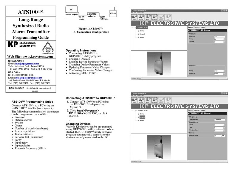
KP Electronic Systems ATS100 Operating instructions

KP Electronic Systems

KP Electronic Systems ATS100 Operating instructions

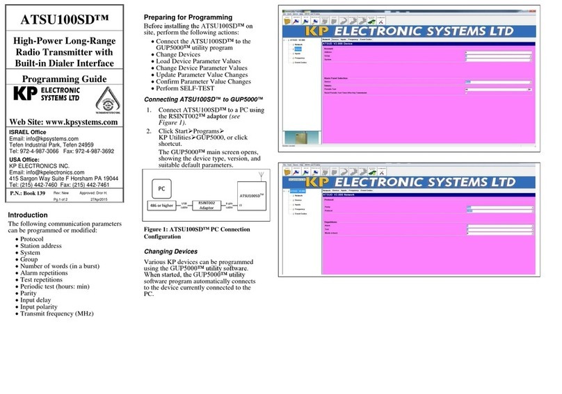
KP Electronic Systems ATSU100SD Operating instructions

KP Electronic Systems

KP Electronic Systems ATSU100SD Operating instructions

Popular Transmitter manuals by other brands

Linx HT Keyfob Data guide

Linx

Linx HT Keyfob Data guide

Burkert GENERIC 8400 operating instructions

Burkert

Burkert GENERIC 8400 operating instructions

Ashcroft KM41 installation instructions

Ashcroft

Ashcroft KM41 installation instructions

Emerson Rosemount 3051S Series Manual supplement

Emerson

Emerson Rosemount 3051S Series Manual supplement

NTI IRT-64X32 Operation manual

NTI

NTI IRT-64X32 Operation manual

WIKA A-10 operating instructions

WIKA

WIKA A-10 operating instructions

Extron electronics XTP T VGA user guide

Extron electronics

Extron electronics XTP T VGA user guide

Emerson Micro-Motion 2400S Configuration and Use Manual

Emerson

Emerson Micro-Motion 2400S Configuration and Use Manual

Emerson Rosemount 3144P Reference manual

Emerson

Emerson Rosemount 3144P Reference manual

Lectrosonics UM195B Operating and troubleshooting guide

Lectrosonics

Lectrosonics UM195B Operating and troubleshooting guide

Erreka LIRA instructions

Erreka

Erreka LIRA instructions

THine THCV235 manual

THine

THine THCV235 manual

Lectrosonics UM400a instruction manual

Lectrosonics

Lectrosonics UM400a instruction manual

Emerson Rosemount X-well 648 Reference manual

Emerson

Emerson Rosemount X-well 648 Reference manual

RIB ACG6202 manual

RIB

RIB ACG6202 manual

ABB 3299-47918 quick start guide

ABB

ABB 3299-47918 quick start guide

Emerson Micro Motion ELITE instruction manual

Emerson

Emerson Micro Motion ELITE instruction manual

Dogtra RR Deluxe Code setting guide

Dogtra

Dogtra RR Deluxe Code setting guide

manuals.online logo
manuals.online logoBrands
  • About & Mission
  • Contact us
  • Privacy Policy
  • Terms and Conditions

Copyright 2025 Manuals.Online. All Rights Reserved.