NTI IRT-64X32 User manual

MAN037 Rev Date 12/2/2004
IRT-64X32
IRT-64
Infrared Remote Transmitters
Operation Manual
NETWORK
TECHNOLOGIES
INCORPORATED
Tel:330-562-7070
Fax:330-562-1999
1275 Danner Dr
Aurora, OH 44202
www.nti1.com
NTI R
123
456
789
0IN
SYS
Lo Batt
NTI R
Network Technologies Inc
IRT-64
123
456
789
0
OUT IN
SYS
Lo Batt
NTI R
Network Technologies Inc
IRT-64X32
SW SW

MAN037 Rev Date 12/2/2004
Warranty Information
The warranty period on this product (parts and labor) is one (1) year from the date of purchase. Please contact Network
Technologies Inc at (800) 742-8324 (800-RGB-TECH) or (330) 562-7070 or visit our website at http://www.nti1.com for
information regarding repairs and/or returns. A return authorization number is required for all repairs/returns.
COPYRIGHT
Copyright © 2004 by Network Technologies Inc. All rights reserved. No part of this publication may be reproduced, stored in a
retrieval system, or transmitted, in any form or by any means, electronic, mechanical, photocopying, recording, or otherwise,
without the prior written consent of Network Technologies Inc, 1275 Danner Drive, Aurora, Ohio 44202.
CHANGES
The material in this guide is for information only and is subject to change without notice. Network Technologies Inc reserves the
right to make changes in the product design without reservation and without notification to its users.

MAN037 Rev Date 12/2/2004
TABLE OF CONTENTS
INTRODUCTION.............................................................................................................................................................1
FEATURES AND FUNCTIONS.......................................................................................................................................1
KEYPAD ......................................................................................................................................................................1
LCD Display.................................................................................................................................................................1
HOW TO USE THE IRT..................................................................................................................................................2
Infrared Remote Operation for Audio/Video Matrix Switches (IRT-64X32)................................................................2
Change the Switch....................................................................................................................................................2
Change Output Port..................................................................................................................................................3
Change Input Port.....................................................................................................................................................3
Set Configuration......................................................................................................................................................4
Infrared Remote Operation for Single-Output Video Switches (IRT-64).....................................................................5
Change the Switch....................................................................................................................................................5
Change Input Port.....................................................................................................................................................6
Set Configuration......................................................................................................................................................6
BATTERY REPLACEMENT............................................................................................................................................7
SPECIFICATIONS ..........................................................................................................................................................8
TROUBLESHOOTING....................................................................................................................................................8

NTI INFRARED REMOTE TRANSMITTERS
1
123
456
789
0
OUT IN
SYS
Lo Batt
NTI R
Network Technologies Inc
IRT-64X32
SW
INTRODUCTION
The IRT-64X32 (or IRT) is an infrared remote transmitter that enables the user to control up to four (4) NTI VEEMUX Audio/Video
Matrix switches via an infrared receiver from up to 50 feet away (with an unobstructed view). The IRT is battery-powered and
always ready to use. The IRT will have a blank display unless an action is being selected by the user. The IRT enables the user
to make connections between any input (video source) and any output (display device) on up to four (4) separate switches.
The IRT-64 (also an IRT) is used to control up to four (4) NTI VEEMUX single-output video switches.
Note: Multiple switches that are located close to each other and are to be individually controlled must be pre-configured
(by NTI) to be identified by the IRT as switches #1, #2, #3, or #4. Please ask your salesperson to have switches
configured accordingly at time of order. Unless otherwise specified, by default, all IRT-enabled switches will be
configured as switch #1.
Subnote: Single-output switches with greater than 32 inputs must be configured to be identified by the IRT as switch #1
or #2.
Materials included:
•IRT-64X32 Infrared Remote Transmitter for audio/video matrix switches
-OR-
IRT-64 Infrared Remote Transmitter for single-output video switches
•(2) AA Cell Batteries- installed
FEATURES AND FUNCTIONS
KEYPAD
¾Buttons Numbered 0-9 – Used for port selection
¾OUT – Pressed to validate and transmit the Output selection (IRT-64X32 only)
¾IN – Pressed to validate and transmit the Input selection
¾SYS – Pressed to choose the switch to be controlled or to configure the
maximum number of inputs/outputs
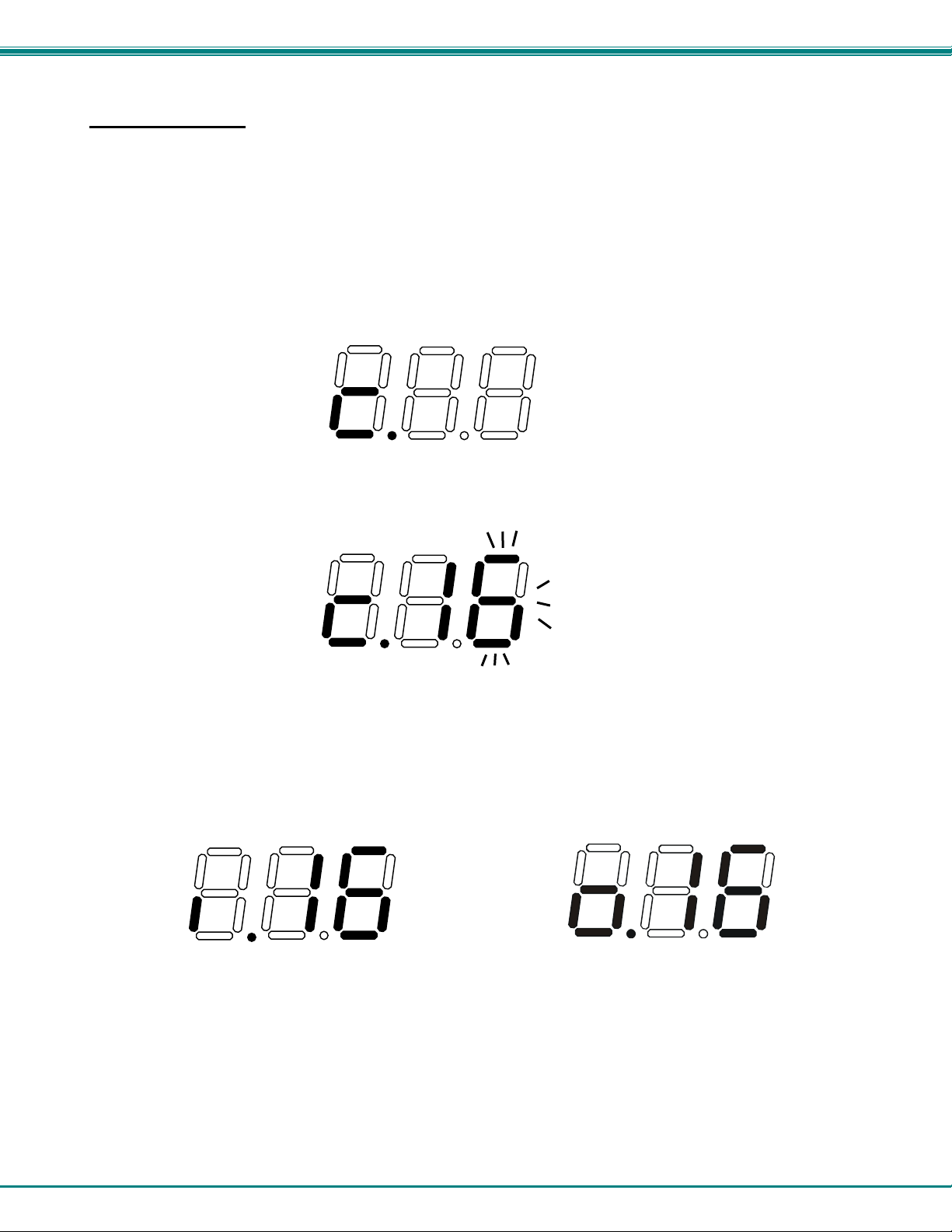
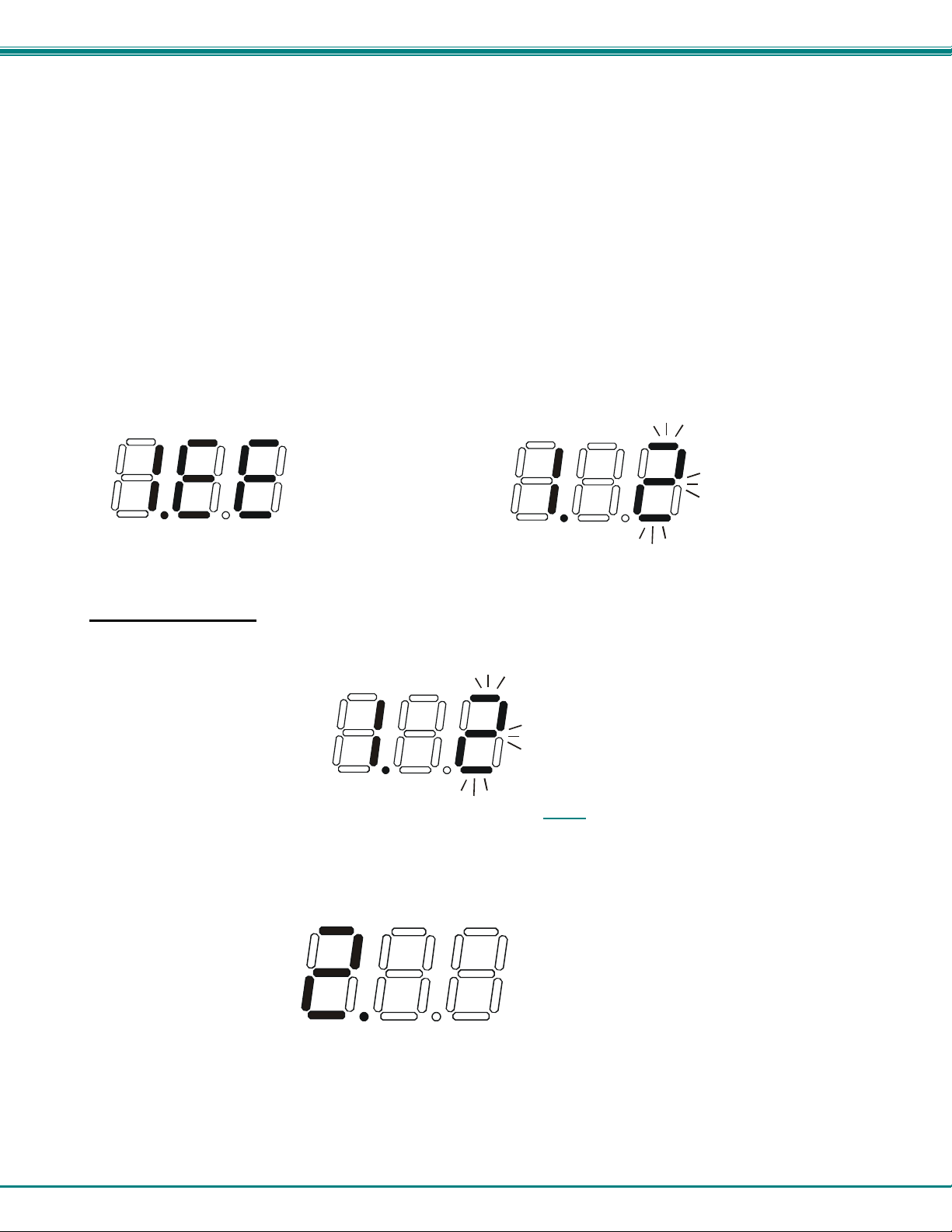
LCD Display
¾The first digit of the LCD will display the number of the switch to be controlled
followed by the decimal point. This way the user will always know which switch
will be effected by the IRT.
¾The last two digits in the LCD represent 1) the desired input or output port to be
connected or 2) the desired switch to be controlled when changing switches.
¾The "Lo Batt" decimal point will illuminate when the user should change the
batteries.
¾The LCD will automatically power-down after 30 seconds of non-use and
power-up with the press of any button.
Lo BattSW
Represents Input or
Output
Represents switch to be controlled

NTI INFRARED REMOTE TRANSMITTERS
2
HOW TO USE THE IRT
Infrared Remote Operation for Audio/Video Matrix Switches (IRT-64X32)
The IRT-64X32 enables the user to control the connections of up to 32 input ports and 16 output ports on up to four (4) separate
NTI audio/video matrix switches. When any key is pressed, the IRT will power ON. A number key should always be pressed
first unless a change to the configuration is desired (see "Set Configuration" on page 4). When a number key is pressed the LCD
will display that number blinking. What to press next depends on what action is desired;
•change the switch to be controlled
•change the output port
•change the input port
Note: The user must always change or confirm the output port first and the input port second
If the "SYS", "IN" or "OUT" key is pressed first, the LCD will display the current switch followed by the decimal point and an error
signal "EE". The error signal will display because there is no number to be displayed. A number key must always be pressed
before a "SYS", "IN" or "OUT" key is pressed.
Exception: The "SYS" key is pressed first when setting the configuration. (See page 4)
Power ON with SYS, IN or OUT keys Power ON with "2" key
Change the Switch
Press the number of the switch to be controlled. The number selected will be blinking in the last digit.
FYI: If the user realizes that an invalid number has been introduced before pressing either the "SYS", "IN", or "OUT"
buttons, a correction can be made by pressing the correct number. If the correct number is a single digit, it must be
preceded by a "0" to make the correction.
Press the "SYS" key. The blinking number will become blank and the switch number will update.
Note: If the number entered is larger than 4, when the "SYS" key is pressed the LCD will display the current switch and
the error signal "EE".

NTI INFRARED REMOTE TRANSMITTERS
3
Change Output Port
Press the desired port number. If there is no change in the desired output port, the output port must still be selected. As the
digits are selected, the last number entered will blink. The LCD will also display the current switch number followed by the
decimal point.
With the desired port number selected, point the IRT at the switch/receiver and press the "OUT" button to transmit the selection
and make the change. The blinking number in the LCD will stop blinking. An LED on the receiver will illuminate.
FYI: If the switch did not receive the data the LED will not illuminate. The user can re-send the same data by pressing
the "OUT" button again. The LED at the receiver will illuminate to indicate a completed transmission from the IRT..
Note: If the number introduced is larger than the maximum number of outputs the IRT is configured for, then once the
"OUT" key is pressed the LCD will display the current switch and the error signal "EE".
Change Input Port
Press the desired port number. As the digits are selected, the last number entered will blink. The LCD will also display the
current switch number followed by the decimal point.
With the desired port number selected, point the IRT at the switch/receiver and press the "IN" button to transmit the selection and
make the change. The blinking number in the LCD will stop blinking. The LED at the receiver will go OFF.
FYI: If the switch did not receive the data the LED will not go OFF. The user can re-send the same data by pressing the
"IN" button again. The illuminated LED on the receiver will go OFF when the received data is complete.
Note: If the number introduced is larger than the maximum number of inputs that the IRT is configured to control, then
once the "IN" key is pressed the LCD will display the current switch and the error signal "EE".

NTI INFRARED REMOTE TRANSMITTERS
4
Set Configuration
The IRT-64x32 factory default setting is 32 inputs and 16 outputs. When the batteries are changed the setting will return to the
default value. At the default setting the IRT has the ability control any matrix switch with up to 32 inputs and 16 outputs without
changing the configuration. However, when controlling smaller switches without changing the configuration it is up to the user to
press valid number(s). To avoid confusion, it is recommended to configure the IRT to communicate with the largest switch to be
controlled.
To change the maximum number of inputs or outputs:
1. From power-down state (blank LCD) press and hold the "SYS" button for at least 3 seconds. The LCD will first display an
error message but after 3 seconds the letter "c" will display:
2. Enter the number of inputs or outputs. As the digits are entered, they will be displayed and the last one entered will blink.
Note: Only the inputs OR the outputs may be configured each time the configuration function is used. To perform
another configuration operation the user must start again at "Set Configuration" step 1.
3. Accept the choice by pressing the "IN" button for setting inputs, or the "OUT" button for setting the outputs. The LCD will not
blink anymore and will display “i” (for inputs) or "o" (for outputs) and the number.
Notes:
- The maximum number of inputs and outputs that can be entered is 32 and 16 respectively. If the user introduces a
number larger, the display will show an error signal ("c.EE") and the maximum number will remain at the last valid
value configured.
- If more than one switch is being controlled, the IRT should be configured for the largest switch. It is up to the user
to introduce valid numbers to the smaller switches when making selections.

NTI INFRARED REMOTE TRANSMITTERS
5
Infrared Remote Operation for Single-Output Video Switches (IRT-64)
The IRT-64 enables the user to control connections to up to 64 input ports on two (2) single-output NTI video switches or up to 32
input ports on four (4) single-output NTI video switches. (See table on page 7 for examples of combinations.)
When any key is pressed, the IRT will power ON. A number key should always be pressed first unless a change to the
configuration is desired (see "Set Configuration" on page 6). When a number key is pressed the LCD will display that number
blinking. What to press next depends on what action is desired;
•change the switch to be controlled
•change the input port
If the "SYS" or "IN" key is pressed, the LCD will display the current switch followed by the decimal point and an error signal "EE".
The error signal will display because there is no number to be displayed. A number key must always be pressed before a "SYS"
or "IN" key is pressed.
Exception: The "SYS" key is pressed first when setting the configuration. (See page 6)
Power ON with SYS or IN keys Power ON with "2" key
Change the Switch
Press the number of the switch to be controlled. The number selected will be blinking in the last digit.
FYI: If the user realizes that an invalid number has been introduced before pressing either the "SYS" or "IN" buttons, a
correction can be made by pressing the correct number. If the correct number is a single digit, it must be preceded by a
"0" to make the correction.
Press the "SYS" key. The blinking number will become blank and the switch number will update.
Note: If the number entered is larger than 4, when the "SYS" key is pressed the LCD will display the current switch and
the error signal "EE".

NTI INFRARED REMOTE TRANSMITTERS
6
Change Input Port
Press the desired port number. The IRT-64 will control up to 64 inputs. As the digits are selected, the last number entered will
blink. The LCD will also display the current switch number followed by the decimal point.
With the desired port number selected, point the IRT at the switch/receiver and press the "IN" button to transmit the selection and
make the change. The blinking number in the LCD will stop blinking.
FYI: If for some reason, the switch did not receive the data, the user can send the same data again by pressing the "IN"
button again.
Note: If the number introduced is larger than the maximum number of inputs the switch has, then once the "IN" key is
pressed the LCD will display the current switch and the error signal "EE".
Set Configuration
The IRT-64 factory default setting is 32 inputs with a maximum setting of up to 64 inputs.. When the batteries are changed the
setting will return to the default value. At the default setting the IRT is able to control any single-output switch with up to 32 inputs
without changing the configuration. However, when controlling smaller switches without changing the configuration it is up to the
user to press valid number(s). To avoid confusion, it is recommended to configure the IRT for the largest switch to be controlled.
To change the maximum number of inputs:
1. From power-down state (blank LCD) press and hold the "SYS" button for at least 3 seconds. The LCD will first display an
error message but after 3 seconds the letter "c" will display:
2. Enter the number of inputs. As the digits are entered, they will be displayed and the last one entered will blink.

NTI INFRARED REMOTE TRANSMITTERS
7
Notes:
- The maximum number of inputs that can be entered is 64. If the user introduces a number larger than 64, the display
will show an error signal ( "c.EE") and the maximum numbers of inputs will remain at the last valid value configured.
- If more than one switch is being controlled, the IRT should be configured for the largest switch. It is up to the user
to introduce valid numbers to the smaller switches when making selections.
- If the configuration is set for greater than 32 inputs, then the IRT will control a maximum of 2 switches.
Reminder: Switches with more than 32 inputs must be configured by NTI to be identified by the IRT as switch #1 or #2.
Otherwise the IRT will not control connections to inputs 33-64 on the larger switches.
3. Press the "IN" button to accept the selection. The display will not blink anymore but will display an "I" and the port number to
indicate the new maximum number of input ports in the switch.
EXAMPLES OF SWITCH COMBINATIONS TO BE CONTROLLED BY ONE IRT-64SUGGESTED IRT
CONFIGURATION Switch #1 Switch #2 Switch #3 Switch #4
Max. 32 inputs 32 port 32 port 32 port 32 port
Max. 24 inputs 24 port 16 port 8 port 8 port
Max. 64 inputs 64 port 64 port Not used Not used
BATTERY REPLACEMENT
The IRT has a low-battery indicator to let the user know when it is time to change the batteries. The right-hand decimal point in
the LCD display will illuminate (see illustration belts Thand deThe .16el to deTT sta4

NTI INFRARED REMOTE TRANSMITTERS
8
SPECIFICATIONS
•50 feet maximum operating range between the transmitter and the front of the NTI switch / infrared
receiver.
Note: Line of sight between IRT and receiver must be unobstructed.
•Select up to 16 outputs (for IRT-64X32)
•Select up to 32 inputs (for IRT-64X32) OR up to 64 inputs (for IRT-64)
•Operates with (2) “AA” batteries.
•"Lo Batt" decimal point in LCD will illuminate to indicate a low battery when the battery voltage drops to approximately 2.25
volts.
TROUBLESHOOTING
IRT-64X32
PROBLEM SOLUTION
IRT is not selecting output •Check battery
•Make sure you are using the correct IRT for the switch. (Check model number
on the front of the IRT.)
•The IRT may be configured to control the wrong switch or the wrong size of
switch (see "Set Configuration" on page 4)
IRT is not selecting input •Check battery
•The IRT may be configured to control the wrong switch or the wrong size of
switch (see "Set Configuration" on page 4)
IRT-64
PROBLEM SOLUTION
IRT is not selecting input •Check battery
•The IRT may be configured to control the wrong switch or the wrong size of
switch (see "Set Configuration" on page 6)
MODEL NO: IRT-64X32
IRT-64
SERIAL NO: ______________________
DATE: ______________________
INSPECTED BY: ______________
Man037 12/2/04
This manual suits for next models
1
Table of contents
Other NTI Transmitter manuals
Popular Transmitter manuals by other brands

Lectrosonics
Lectrosonics UM195B Operating and troubleshooting guide

Emerson
Emerson Rosemount X-well 648 Reference manual

SRK Electronics
SRK Electronics MFTX100 Operation and service manual

RIB
RIB ACG6202 manual

Linx
Linx MDEV-315-HH-LR8-HS user guide

Extron electronics
Extron electronics A/V Receiver MTP 4T 15HD RS user manual