DANGER
Danger due to pressure loaded lines.
When working on pressure loaded lines, uncontrolled or squirting fluids can
lead to accidents and severe injuries or even result in death.
●Always depressurize all lines during all work on the unit and before dis-
assembly.
WARNING
Danger due to falling loads and or loads falling over!
Due to the size and weight of the device, accidents can occur resulting in
severe injuries or death during transport and shipping.
●Compliancewithapplicableindustrialsafetyrequirementsismandatory.
●Use only suitable means of conveyance and lifting tackle with sufficient
load-bearing capacity.
●Attach the lifting tackle in such a manner that it cannot slip.
●Secure the device so that toppling over and falling down is impossible.
●Always avoid jerks, impacts and strong vibrations during transportation.
●Never walk under suspended loads, never work under suspended
loads.
●To prevent damage to the device, be extremely cautious when shipping
or transporting.
●Wear suitable protective clothing.
WARNING
Danger due to hazardous fluid!
Danger of death upon contact with hazardous fluids and when inhaling va-
pours from these liquids.
●Comply with the safety data sheets and regulations on handling the
hazardous liquids!
●Collect and dispose leaks of hazardous materials so that no hazards
arise for people or the environment.
●Comply with national and international rules at the place of installation.
●Wear suitable protective clothing.
CAUTION
Danger due to hot surfaces!
When operating the device with hot media, there is a danger of being
burned and scalded when touching the hot surfaces.
●At medium temperatures above 60 °C, take measures against uninten-
ded contact.
●Wear safety gloves.
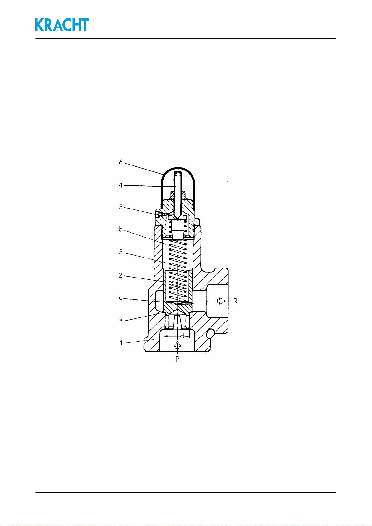
Pressure Relief Valves SPV / SPVF
82011-01-13 BSPV0006EN_D0024980002_04