manuals.online logo
Brands
  1. Home
  2. •
  3. Brands
  4. •
  5. Kramer
  6. •
  7. Marine Audio
  8. •
  9. Kramer EXT3-POE-XR-R User manual

Kramer EXT3-POE-XR-R User manual

EXT3-POE-XR-R Quick Start
P/N:
2900- 301563QS
Rev:
1
Scan for full manual
EXT3-POE-XR-R Quick Start Guide
This guide helps you install and use your EXT3-POE-XR-R for the first time.
Go to www.kramerav.com/downloads/EXT3-POE-XR-R to download the latest user manual and check if
firmware upgrades are available.
Step 1: Check what’s in the box
EXT3-POE-XR-R 4K HDMI/USB Receiver
1 Bracket set
1 Quick start guide
1 Power adapter and cord
4 Rubber feet
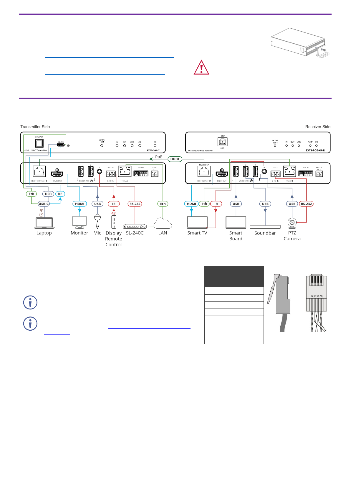
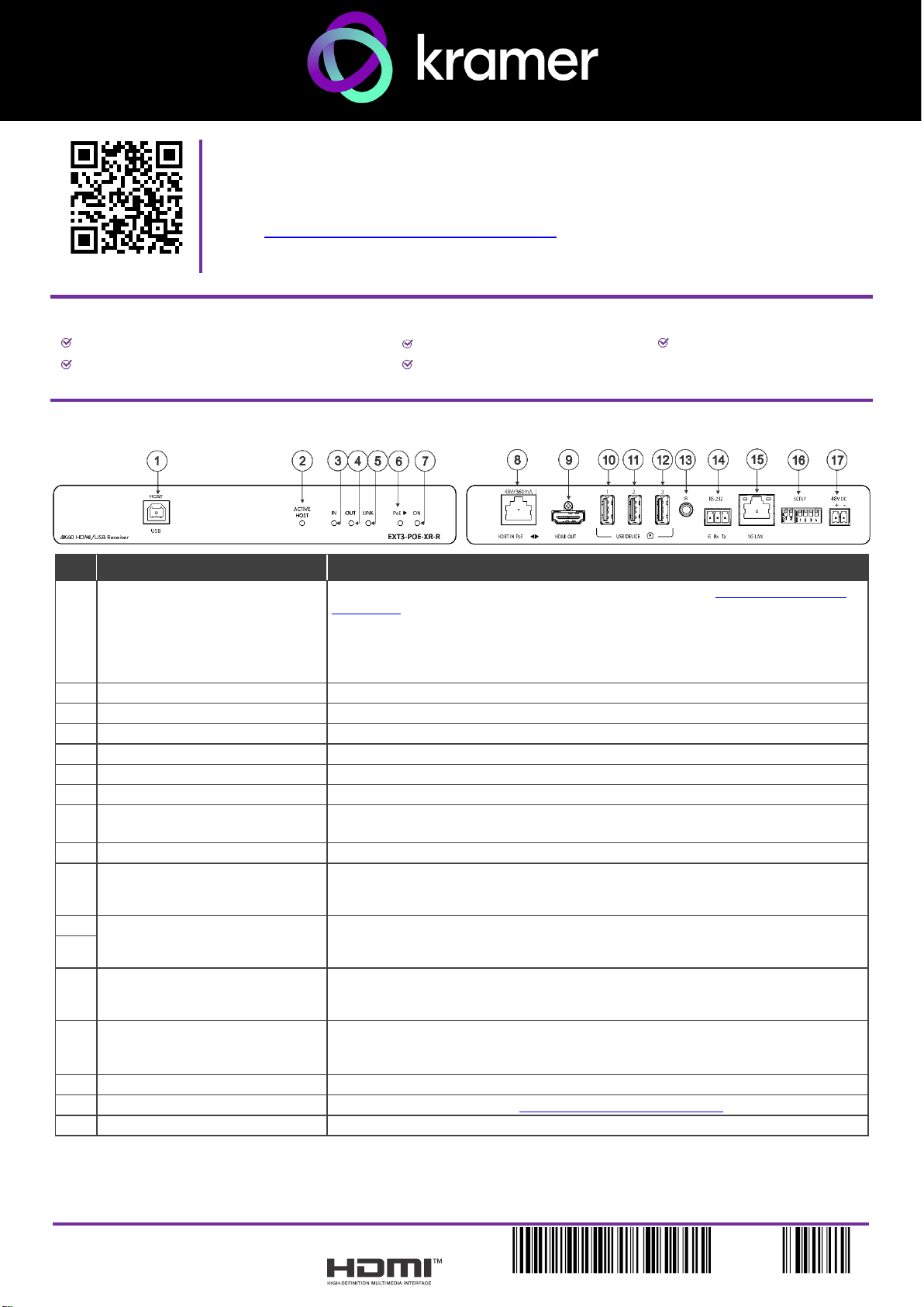
Step 2: Get to know your EXT3-POE-XR-R
#
Feature
Function
1
HOST USB B 2.0 Connector
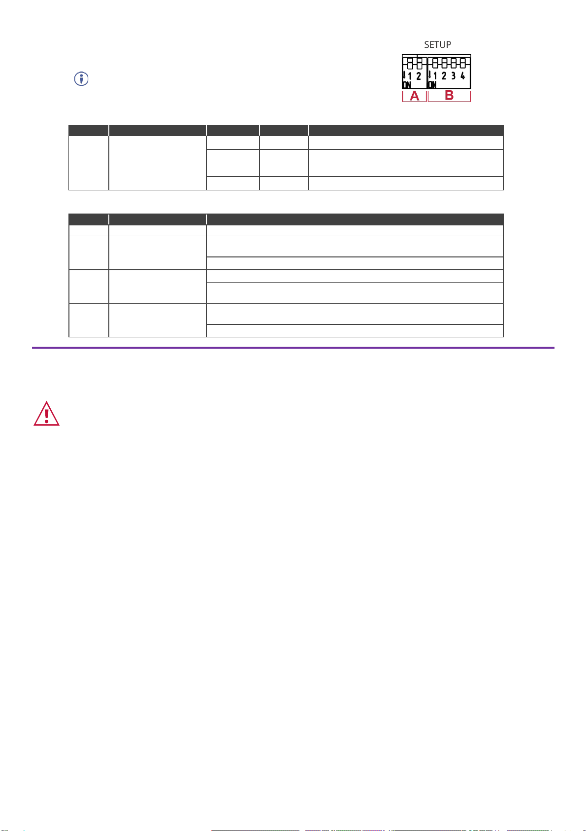
When the device DIP-switch is set to active host as defined in Step 4:Connect inputs
and outputs, connect a USB host (for example, a room PC) to communicate with the
USB peripheral devices (for example, a smart board) connected to USB device ports
on this device or the connected remote device.
Note that an active host can be set only one device, either the transmitter or the
receiver, not both.
2
ACTIVE HOST LED
Lights orange when the USB host side is active.
3
IN LED
Lights blue when an active HDMI input signal is detected on HDMI IN.
4
OUT LED
Lights blue when an output acceptor device is connected.
5
LINK LED
Lights green when the HDBT active link connection is established.
6
PoE► LED
Lights green when power-providing over HDBT is active.
7
ON LED
Lights green when the device receives power.
8
HDBT IN PoE◄►
Connect to the HDBT connector on a paired PoE-accepting transmitter device (for
example, a EXT3-C-XR-T device).
9
HDMI OUT
Connect to an HDMI acceptor.
10
USB A 2.0 Charging Connector 1
Connect to the USB local peripheral devices (for example, a USB PTZ camera). When
the USB Host PC is disconnected, the USB signal and charging power for this port
are inactive.
11
USB A 2.0 Charging Connectors
2-3
Connect to the USB local peripheral devices (for example, a USB camera, a
soundbar, a microphone and so on). When the USB Host PC is disconnected, the
USB charging power for this port continues to be active.
12
13
IR 3.5mm Mini Jack Connector
Bidirectional IR connection. Outputs a received IR signal (from the HDBT transmitter)
to connected IR emitter or transmits an IR signal (from IR sensor) to the HDBT
transmitter.
14
RS-232 3-pin Terminal Block
Bidirectional RS-232 connection. Outputs a signal received from a controller device
(for example, SL-240C) to control a remote device via serial connection (for example,
the remotely connected PTZ USB camera).
15
1G LAN RJ-45 Connector
Connect to LAN for Ethernet extension to the transmitter.
16
SETUP 4-way DIP-switch
Sets the device behavior (see Step 4:Connect inputs and outputs).
17
48V DC
Connect to the power supply.
Step 3: Mount EXT3-POE-XR-R
Install EXT3-POE-XR-R using one of the following methods:
•Attach the rubber feet and place the unit on a flat surface.
•Fasten a bracket (included) on each side of the unit and attach it to a flat surface
(see www.kramerav.com/downloads/EXT3-POE-XR-R).
•Mount the unit in a rack using the recommended rack adapter
(see www.kramerav.com/product/EXT3-POE-XR-R).
•Ensure that the environment (e.g., maximum ambient temperature &
air flow) is compatible for the device.
•Avoid uneven mechanical loading.
•Appropriate consideration of equipment nameplate ratings should be
used for avoiding overloading of the circuits.
•Reliable earthing of rack-mounted equipment should be maintained.
•Maximum mounting height for the device is 2 meters.
Step 4: Connect inputs and outputs
Always switch OFF the power on each device before connecting it to your EXT3-POE-XR-R.
Wiring the RJ-45 Connectors
This section defines the HDBT pinout, using a STRAIGHT pin-to-pin cable
with
RJ-45 connectors.
EIA /TIA 568B
PIN
Wire Color
1
Orange / White
It is recommended that the cable ground shielding be
connected/soldered to the connector shield.
2
Orange
3
Green / White
4
Blue
To achieve specified extension distances, use the recommended
Kramer cables available at www.kramerav.com/product/EXT3-
POE-XR-R. Using third-party cables may cause damage!
5
Blue / White
6
Green
7
Brown / White
8
Brown
DIP-Switch Settings
The DIP-switches are used to set the HDBT range, upgrade the firmware,
Determine IR signal pass-through.
All the DIP-switches are set to OFF (up) by default.
A –DIP-switch Settings
DIP #
Feature
DIP-1A
DIP-2A
State Description
1A, 2A
HDBT Range Mode
Off
Off
Standard range mode.
Off
On
Ultra-long range mode.
On
Off
TBD
On
On
TBD
B –DIP-switch Settings
Changes to DIP-switches 2B and 3B only take effect after power cycling the device.
DIP #
Feature
DIP-switch Settings
1B
TBD
2B
Active USB Host
Off (default) –The device is configured as the host for connected USB
devices.
On –USB are configured as slaves to the remote connection.
3B
IR Modulation
Off (default) –IR pass-thru is enabled.
On –IR pass-thru is disabled (add a 38KHz modulation to the IR output
signal).
4B
RS-232 operation
Mode
Off (default) –RS-232 FW programming is inactive (Normal operation
mode is enabled).
On –RS-232 FW programming is active.
Step 5: Connect power
Connect the power adaptor to theEXT3-POE-XR-R and the power cord and plug it into the mains electricity. Alternatively,
receive PoE via HDBT.
Safety Instructions (See www.kramerav.com for updated safety information)
Caution:
•There are no operator serviceable parts inside the unit.
Warning:
•Use only the power cord that is supplied with the unit.
•Disconnect the power and unplug the unit from the wall before installing.
The terms HDMI, HDMI High-Definition Multimedia Interface, and the HDMI Logo are trademarks or registered trademarks of HDMI Licensing Administrator, Inc.

Popular Marine Audio manuals by other brands

DNA MA3 instruction manual

DNA

DNA MA3 instruction manual

MTX TP112 user manual

MTX

MTX TP112 user manual

Behringer eurolive b115w quick start guide

Behringer

Behringer eurolive b115w quick start guide

Sony CDX-M20 Specifications

Sony

Sony CDX-M20 Specifications

ASA Electronics MSR180 owner's manual

ASA Electronics

ASA Electronics MSR180 owner's manual

Sony XS-AR1025 Installation/connections

Sony

Sony XS-AR1025 Installation/connections

Akai CSP-8500 instruction manual

Akai

Akai CSP-8500 instruction manual

Jensen MS2013BT Installation and operation manual

Jensen

Jensen MS2013BT Installation and operation manual

JL Audio M6-8IB-L owner's manual

JL Audio

JL Audio M6-8IB-L owner's manual

Pioneer TS-MR1640 instruction manual

Pioneer

Pioneer TS-MR1640 instruction manual

Altec Lansing 55-4A SPEAKER SYSTEM manual

Altec Lansing

Altec Lansing 55-4A SPEAKER SYSTEM manual

Rockford Fosgate PMX-8DH Installation and operation guide

Rockford Fosgate

Rockford Fosgate PMX-8DH Installation and operation guide

Beta Three S400a user manual

Beta Three

Beta Three S400a user manual

Navilock NL-8022MU Operation manual

Navilock

Navilock NL-8022MU Operation manual

Audiovox AquaTronics MS1550 owner's manual

Audiovox

Audiovox AquaTronics MS1550 owner's manual

Polk Mono UM2 Installation and operation manual

Polk Mono

Polk Mono UM2 Installation and operation manual

Sony XS-HA1724 Installation/connections

Sony

Sony XS-HA1724 Installation/connections

Aquatic AQ-CD-1 Specifications

Aquatic

Aquatic AQ-CD-1 Specifications

manuals.online logo
manuals.online logoBrands
  • About & Mission
  • Contact us
  • Privacy Policy
  • Terms and Conditions

Copyright 2025 Manuals.Online. All Rights Reserved.