manuals.online logo
Brands
  1. Home
  2. •
  3. Brands
  4. •
  5. Kramer
  6. •
  7. Matrix Switcher
  8. •
  9. Kramer VP-4x4K User manual

Kramer VP-4x4K User manual

Other manuals for VP-4x4K

3

Other Kramer Matrix Switcher manuals

Kramer Sierra Viddeo 84V3S User manual

Kramer

Kramer Sierra Viddeo 84V3S User manual

Kramer VS-606xl User manual

Kramer

Kramer VS-606xl User manual

Kramer VP-88ETH User manual

Kramer

Kramer VP-88ETH User manual

Kramer 20-04400030 User manual

Kramer

Kramer 20-04400030 User manual

Kramer VS-88SDI User manual

Kramer

Kramer VS-88SDI User manual

Kramer VP-8x8 User manual

Kramer

Kramer VP-8x8 User manual

Kramer Sierra Pro XL 1208V3S User manual

Kramer

Kramer Sierra Pro XL 1208V3S User manual

Kramer VS-44AV User manual

Kramer

Kramer VS-44AV User manual

Kramer VS-42HDCP User manual

Kramer

Kramer VS-42HDCP User manual

Kramer XL 1204V4 User manual

Kramer

Kramer XL 1204V4 User manual

Kramer Sierra Video 1208V3S User manual

Kramer

Kramer Sierra Video 1208V3S User manual

Kramer XL 1608V2S User manual

Kramer

Kramer XL 1608V2S User manual

Kramer VS-44H User manual

Kramer

Kramer VS-44H User manual

Kramer VP-436 User manual

Kramer

Kramer VP-436 User manual

Kramer VS-62H User manual

Kramer

Kramer VS-62H User manual

Kramer XL 3232V User manual

Kramer

Kramer XL 3232V User manual

Kramer 3232HD User manual

Kramer

Kramer 3232HD User manual

Kramer VS-4228 User manual

Kramer

Kramer VS-4228 User manual

Kramer AFM-20DSP-LE User manual

Kramer

Kramer AFM-20DSP-LE User manual

Kramer VS-5x4 User manual

Kramer

Kramer VS-5x4 User manual

Kramer Sierra Video 3232V5 User manual

Kramer

Kramer Sierra Video 3232V5 User manual

Kramer VP-727 User manual

Kramer

Kramer VP-727 User manual

Kramer VS-42HC User manual

Kramer

Kramer VS-42HC User manual

Kramer VS-44HDxl User manual

Kramer

Kramer VS-44HDxl User manual

Popular Matrix Switcher manuals by other brands

AMX AVS-OCT-3264-210 Product View

AMX

AMX AVS-OCT-3264-210 Product View

Communica CST-2042 user manual

Communica

Communica CST-2042 user manual

Thinklogical TLX48 product manual

Thinklogical

Thinklogical TLX48 product manual

Broadcast Tools SS 8.2 Installation and operation manual

Broadcast Tools

Broadcast Tools SS 8.2 Installation and operation manual

Altimium MATF32 user manual

Altimium

Altimium MATF32 user manual

Monoprice Blackbird 15377 user manual

Monoprice

Monoprice Blackbird 15377 user manual

Link HD8X8 user manual

Link

Link HD8X8 user manual

TESmart HMA0402A40 quick start guide

TESmart

TESmart HMA0402A40 quick start guide

AMX AVS-OP-2020-117 Product View

AMX

AMX AVS-OP-2020-117 Product View

Shinybow USA SB-8811 instruction manual

Shinybow USA

Shinybow USA SB-8811 instruction manual

ALFAtron ALF-MUK44N manual

ALFAtron

ALFAtron ALF-MUK44N manual

Optimus Compact operating instructions

Optimus

Optimus Compact operating instructions

PTN FMX12 user manual

PTN

PTN FMX12 user manual

Lindy 38042 quick start guide

Lindy

Lindy 38042 quick start guide

AMX Precis LT instruction manual

AMX

AMX Precis LT instruction manual

CYP nT15GX01 Operation manual

CYP

CYP nT15GX01 Operation manual

Extron electronics DTP CrossPoint 108 4K user guide

Extron electronics

Extron electronics DTP CrossPoint 108 4K user guide

CYP PUV-662-4K22 Operation manual

CYP

CYP PUV-662-4K22 Operation manual

manuals.online logo
manuals.online logoBrands
  • About & Mission
  • Contact us
  • Privacy Policy
  • Terms and Conditions

Copyright 2025 Manuals.Online. All Rights Reserved.

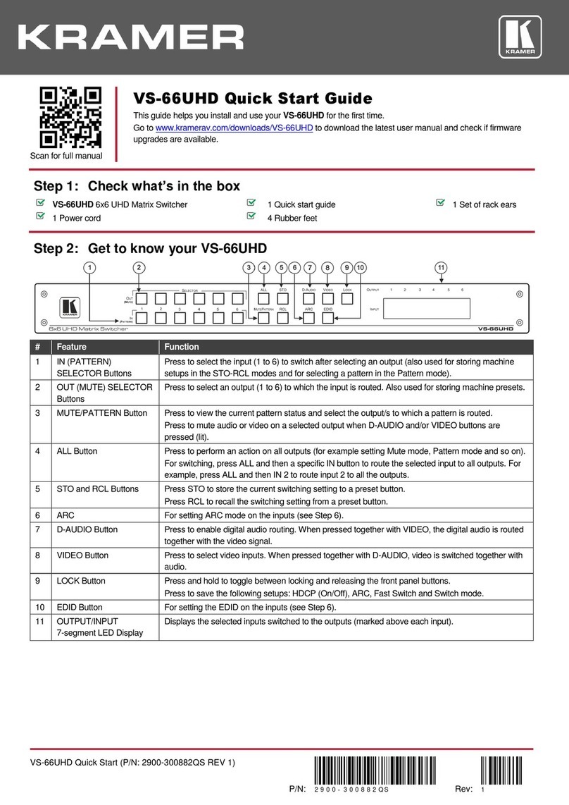
VP-4x4K Quick Start
P/N:
2900- 301261QS
Rev:
2
Scan for full manual
VP-4x4K Quick Start Guide
This guide helps you install and use your VP-4x4K for the first time.
Go to www.kramerav.com/downloads/VP-4x4K to download the latest user manual and check if firmware
upgrades are available.
Step 1: Check what’s in the box
VP-4x4K 4x4 UXGA/Audio Matrix Switcher
1 Set of rack ears
4 Rubber feet
Kramer RC-IR3 IR Remote Control Transmitter
1 Power cord
1 Quick start guide
Step 2: Get to know your VP-4x4K
#
Feature
Function
1
POWER Switch
Illuminated switch for turning the unit ON or OFF
2
IR Receiver
Signals from the remote control transmitter illuminate the LED
3
SELECTO
R Buttons
OUT
Select the output to which the input is switched
IN
Select the input to switch to the output
When a signal is detected, the input button illuminates in green
The SELECTOR IN and OUT buttons also store/recall the input/output configurations
4
ALL Button
Pressing ALL before pressing an input button connects that input to all outputs
For example, press ALL and then Input button # 2 to connect input # 2 to all the outputs
5
OFF Button
Pressing OFF after pressing an output button disconnects that output from the inputs. To disconnect
all the outputs, press the ALL button and then the OFF button
6
AFV Button
When illuminated, the audio channels follow the video channels. The button is illuminated when the
AFV mode is selected. If the AUDIO differs from the VIDEO, the TAKE button will flash, and you
have to press the TAKE button to confirm the modification
7
VID Button
When illuminated, actions relate to video
The VID button is illuminated when in breakaway mode and actions relate to video
8
AUD Button
When illuminated, actions relate to audio
The AUD button is illuminated when in breakaway mode and actions relate to audio
9
STO Button
Pressing STO (STORE) followed by an output or an input button stores the current setting
Press the STO and LOCK buttons simultaneously to set the delay time. For example, press STO and
then the Output button # 3 to store in Setup # 3
10
LOCK Button
Disengages the front panel switches
11
RCL Button
Pressing RCL (RECALL) followed by an output or an input button displays a stored setup
12
TAKE Button
Pressing TAKE toggles the mode between the CONFIRM mode and the AT ONCE mode (user
confirmation per action is unnecessary). When in CONFIRM mode, actions are confirmed by
pressing the TAKE key. For example, press STO and then the Output button # 3 to store in Setup # 3
When in the CONFIRM mode, the TAKE button illuminates
13
AUDIO GAIN
Button
Press to adjust the audio input or output gain
#
Feature
Function
14
- Button
Press to decrease the numerical value
By pressing the + or - buttons continuously, you can speed up their response. For step-by-step
response, press and release these buttons as many times as needed
Gain, switching delay time and machine number
15
+ Button
Press to increase the numerical value
16
STATUS 7-
segment Display
Displays the selected input switched to the output (marked above each input)
Also displays the number of IN and OUT ports, the firmware version number, the MACHINE # and
the audio gain level
#
Feature
Function
17
INPUT 15-pin HD Connectors
Connect to the video sources (from 1 to 4)
18
OUTPUT 15-pin HD Connectors
Connect to the acceptors (from 1 to 4)
19
AUDIO INPUTS 3.5mm Mini Jack
Connect to the unbalanced stereo audio sources (from 1 to 4)
20
AUDIO OUTPUTS Terminal block connectors
Connect to the balanced stereo audio acceptors (from 1 to 4)
21
PROGRAM Button
Not used (for technical staff use only)
22
Ethernet Connector
Connects to the PC or other Serial Controller through computer networking
23
Factory Reset Button
Press to reset to the factory default definitions:
IP number −192.168.1.39
Mask –255.255.0.0
Gateway –0.0.0.0
UDP port –50000
TCP port –5000
Protocol 3000 commands
All 8 Presets deleted
All audio channels set to 0dB
Machine name –the last four digits of the machine's serial number
DHCP disabled
Turn the POWER switch OFF and then ON again while pressing the
Factory Reset button. The unit will power up and load its memory with the
factory default definitions
24
RS-485 TERM DIP-switch
DIP 1 is for RS-485 Termination, DIP 2 is not used
25
RS-485 Terminal Block Port
Pins B (-) and A (+) are for RS-485; Pin G (Ground) may be connected to
the shield of the cable if desired
26
RS-232 9-pin D-sub Connector
Connects to the PC or the Remote Controller
27
Power Connector with Fuse
AC connector enabling power supply to the unit
Step 3: Mount VP-4x4K
To rack mount the machine, attach both rack ears
(by removing the screws from each side of the
machine and replacing those screws through the
rack ears) or place the machine on a table.
•Ensure that the environment (e.g., maximum ambient temperature &
air flow) is compatible for the device.
•Avoid uneven mechanical loading.
•Appropriate consideration of equipment nameplate ratings should be
used for avoiding overloading of the circuits.
•Reliable earthing of rack-mounted equipment should be maintained.
Step 4: Connect inputs and outputs
Always switch OFF the power on each device before connecting it to your VP-4x4K.
You can connect DVI-U to an analog (VGA, composite or component video) or digital (HDMI™or DVI) source.
The terms HDMI, HDMI High-Definition Multimedia Interface, and the HDMI Logo are trademarks or registered trademarks of HDMI Licensing Administrator, Inc.
Connecting the audio output
Wiring the RJ 45 Connectors
To a balanced
stereo audio
acceptor:
This section defines the TP pinout, using
a straight pin-to-pin cable with RJ 45
connectors.
EIA /TIA 568B
PIN
Wire Color
1
Orange / White
2
Orange
3
Green / White
To an unbalanced
stereo audio
acceptor:
For HDBT cables, it is recommended
that the cable ground shielding be
connected/soldered to the connector
shield.

4
Blue
5
Blue / White
6
Green
7
Brown / White
8
Brown
Set the RS-485 TERM DIP-switch
RS-485 TERM
ON for RS-485 line termination with 120OFF
for no RS-485 line termination
When cascading machines, set this DIP-switch
to ON for the first and last units only
(otherwise, set it to OFF)
To achieve specified extension distances, use the recommended Kramer cables available at www.kramerav.com/product/VP-4x4K.
Using third-party cables may cause damage!
Step 5: Connect power
Connect the power cord to VP-4x4K and plug it into the mains electricity.
Safety Instructions (See www.kramerav.com for updated safety information)
Caution:
•For products with relay terminals and GPI\O ports, please refer to the permitted rating for an external connection, located next to the
terminal or in the User Manual.
•There are no operator serviceable parts inside the unit.
Warning:
•Use only the power cord that is supplied with the unit.
•Disconnect the power and unplug the unit from the wall before installing.
•Do not open the unit. High voltages can cause electrical shock! Servicing by qualified personnel only.
•To ensure continuous risk protection, replace fuses only according to the rating specified on the product label which located on the
bottom of the unit.
Step 6: Operate VP-4x4K
RS-232 and Ethernet:
EDID
EDID data is passed between Input 1 and Output 1
RS-232
Protocol 2000
Protocol 3000 (Default)
Baud Rate:
9600
Baud Rate:
115,200
Data Bits:
8
Data Bits:
8
Stop Bits:
1
Stop Bits:
1
Parity:
None
Parity:
None
Command Format:
HEX
Command Format:
ASCII
Example (Output 1 to Input 1):
0x01, 0x81, 0x81, 0x81
Example (Output 1 to
Input 1):
#AV 1>1<CR>
Switching Protocol
P2000 -> P3000
P3000 -> P2000
Command:
0x38, 0x80, 0x83, 0x81
Command:
#P2000<CR>
Front Panel:
Press and hold Output 1
and Output 3
simultaneously
Front Panel:
Press and hold Output
1 and Output 2
simultaneously
Ethernet
Default Settings
Reset Settings
IP Address: 192.168.1.39
Power cycle the unit while holding in the Factory Reset button, located on the
rear panel of the unit.
TCP Port #: 5000
UDP Port #: 50000
Technical Specifications
Inputs:
4 UXGA on 15-pin HD connectors
4 unbalanced audio stereo signals on 3.5mm mini plug connectors
Outputs:
4 UXGA on 15-pin HD connectors
4 balanced audio stereo signals on 5-pin terminal block connectors
Max. Output Level:
Video: 2.2Vpp
Audio: >15Vpp
Bandwidth (-3dB):
Video: 400MHz
Audio: 19kHz
Diff. Gain:
0.07%
Diff. Phase:
0.03 Deg.
K-Factor:
<0.05%
S/N Ratio:
Video: 73.5dB @5MHz
Audio: 76dB unweighted
Crosstalk (all hostile):
Video: -48dB @5MHz
Audio: -54dB @1MHz
Controls:
Input-output selector, AFV, VID, AUD, STO, LOCK, RCL, TAKE, DELAY,
MACH. #, RS-485, RS-232, REMOTE IR
Coupling:
Video: DC
Audio: AC
Audio THD + Noise:
0.065% @1kHz
Audio 2nd Harmonic:
0.002% @1kHz
Power Source:
100-240V AC, 18VA max.
Operating Temperature:
0° to +40°C (32° to 104°F)
Storage Temperature:
-40° to +70°C (-40° to 158°F)
Humidity:
10% to 90%, RHL non-condensing
Dimensions:
19” x 7” x 1U (W, D, H) rack mountable
Weight:
2.7kg (6 lbs) approx
Accessories:
Power cord, rack “ears”, Windows®-based control software
Specifications are subject to change without notice at www.kramerav.com