Kreg KPHA750 User manual
English 2
French (N. America) 19
Spanish (N. America) 37
French 55
Spanish 73
German 91
OWNER’S MANUAL
We’re here to help.
We want you to have an exceptional project building experience.
If you have questions or need support, please get in touch.
Tell us about your experience.
Your opinion counts. And we’re always looking for ways to improve.
Share your feedback so we can keep growing and innovating for you.
www.kregtool.com/feedback
WARNING Every user must read and follow instructions and safety precautions in this manual.
Failure to do so could result in serious injury. Save manual for future reference.
KPHA750 Pocket-Hole Jig
Docking Station
For use with Kreg 500-Series and 700-Series
Pocket-Hole Jigs

2
Safety Precautions
WARNING Before using a power tool with this product, read and follow the tool manufacturer’s
instructions and safety precautions in addition to the safety precautions below to reduce the risk
of serious injury from hazards such as re, electric shock, or rotating drill bit.
■Always wear personal protective equipment recommended by the manufacturer of the power
tool you are using, such as eye, hearing, or respiratory protection.
■The drill bit is sharp. Handle with care.
■Do not allow familiarity gained from frequent use of your tools to replace safe work practices.
A moment of carelessness is sufcient to cause serious injury.
■Avoid awkward hand positions where a sudden slip could cause contact with the rotating bit.
■When drilling, always ensure workpiece is clamped securely. It is dangerous to hold workpiece
in place by hand.
WARNING Do not operate this tool or any machinery while under the inuence of drugs, alcohol,
or medications.
WARNING This product can expose you to chemicals including Acrylonitrile and other chemicals,
which are known to the State of California to cause cancer and reproductive harm. For more
information go to www.P65Warnings.ca.gov.
Table of Contents
Safety Precautions . . . . . . . . . . . . . 2
Pre-Assembly . . . . . . . . . . . . . . . . 3
Recommended Tools (Not Included). . . 3
Product Description . . . . . . . . . . . 3
Assembly: For 500-Series Jig . . . . . . . 4
Assembly: For 700-Series Jig . . . . . . . 7
Assembly: Adjustable Stop. . . . . . . . . 10
Operation - Folding the Material Support
Wings . . . . . . . . . . . . . . . . . . . .12
Operation - Using the Adjustable Stop . . 13
Removing the Jig from the
DockingStation. . . . . . . . . . . . . . . 15
Care and Cleaning . . . . . . . . . . . . . 16
3
Pre-Assembly
Review this section before you begin. Ensure that you have all tools and materials on hand.
Compare the package with the items listed in the Recommended Tools and Product Description
sections. If any item is missing or lost, do not use this product. Contact Technical Support or
return the product to the place of purchase.
Recommended Tools (Not Included)
Assembling dock for use with 500-Series Jig: Assembling dock for use with 700-Series Jig:
#2 Phillips screwdriver
No tools are required.
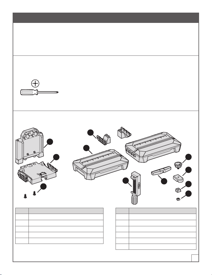
Product Description
A
B
E
D
KF
C
G
H
I
J
Part Description Part Description
A Dock-base back for 500-Series Jig F Adjustable stop arm
B Dock-base platform for 500-Series Jig G Adjustable stop knob
C Dock-base screws (2) for 500-Series Jig H Adjustable stop base
D Dock adapters for 700-Series Jig (2) I Adjustable stop base wedge
E Material support wings (2) J Adjustable stop square nut
K KPHA760 Pocket-hole jig clamp
4
Assembly: For 500-Series Jig
This section describes how to assemble the KPHA750 Pocket-Hole Jig Docking Station for use
with a Kreg 500-Series Jig.
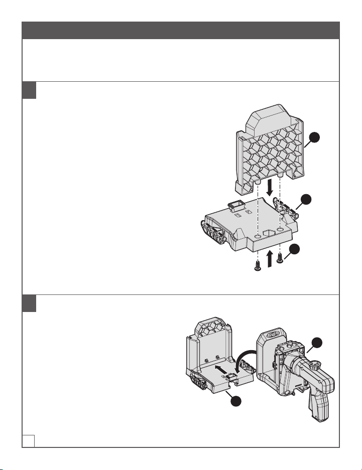
1 Assemble the Dock Base
a. Remove the two screws (C) taped to the
dock-base platform (B).
b. Insert the dock-base back (A) into the
dock-base platform (B):
■The honeycomb side of the dock-
base back (A) faces away from the
dock-base platform (B).
■The two connectors that protrude
from the bottom of the dock-base
back (A) t into the corresponding
holes in the dock-base platform (B).
c. For each connector: Insert a screw (C)
into the connector from the underside
of the dock-base platform(B); then use
a #2 Phillips screwdriver to tighten the
screw (C).
A
B
C
2 Connect the 500-Series Jig to the Dock Base
a. Place the assembled dock base (1) on a
at surface.
b. Slide the 500-Series Jig (2) onto the dock
base until the jig (2) reaches the back of
the assembled dock base (1) and snaps
into position.
2
1

5
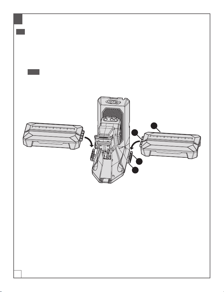
3 Connect the Material Support Wings to the Dock Base
Tip The material support wings also serve as storage boxes.
a. Hold a material support wing (E) right-side up (so that the lid of the storage box is facing up
and opens away from you).
b. Align the connector (1) on the side of the material support wing (E) with the connector (2) on
the side of the dock base; then press the material support wing (E) down rmly so that the
connectors snap together.
Note The bars on the material-support-wing connector (1) snap into the grooves on the
dock-base connector (2).
c. Repeat these steps to connect the other material support wing (E) to the connector (2) on the
opposite side of the dock base.
E
1
2

6
4 Optional: Mount the Dock Base to a Work Surface
If desired, you can mount the dock base to your work surface for added stability.
a. Place the assembled docking station (with or without the 500-Series Jig attached) in the
desired position on your workbench.
b. Drive one Kreg pocket-hole screw (1) through each of the four mounting holes (2) in the
dock-base platform (B).
Note You can use Kreg SML-C125 screws or any other Kreg pocket-hole screw.
B
1
2
7
Assembly: For 700-Series Jig
This section describes how to assemble the KPHA750 Pocket-Hole Jig Docking Station for use
with a Kreg 700-Series Jig.
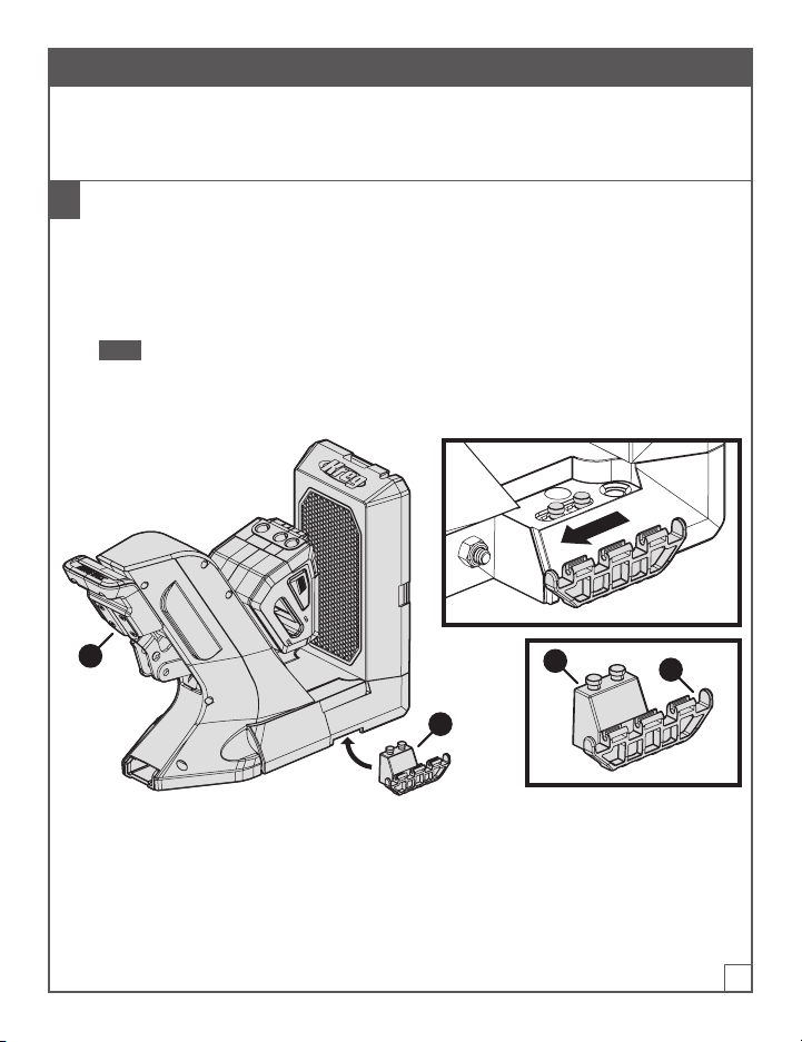
1 Connect the Dock Adapters to the 700-Series Jig
a. Place the 700-Series Jig on a at surface.
b. With one hand, lift one side of the 700-Series Jig slightly.
c. With your other hand, place a dock adapter (D) under the jig so that the attachment pins(1)
t into the corresponding hole on the underside of the jig; then slide the dock adapter (D)
toward the jig handle (3) to lock the dock adapter (D) into position.
Note One side of a dock adapter (D) has attachment pins (1) that t under the jig; the other
side has a connector (2) for a material support wing (not shown). Ensure that the wing-
connector side (2) of the dock adapter (D) extends out from the side of the jig.
d. Repeat steps b and c to connect the other dock adapter (D) on the opposite side of the jig.
D
12
3
8
2 Connect the Material Support Wings to the Dock Adapters
Tip The material support wings also serve as storage boxes.
a. Hold a material support wing (E) right-side up (so that the lid of the storage box is facing up
and opens away from you).
b. Align the connector (1) on the side of the material support wing (E) with the connector (2) on
the dock adapter (D) that extends from the side of the jig; then press the material support
wing (E) down rmly so that the connectors snap together.
Note The bars on the material-support-wing connector (1) snap into the grooves on the
dock-adapter connector (2).
c. Repeat these steps to connect the other material support wing (E) to the dock adapter (D) on
the opposite side of the jig.
E
1
2
D

9
3 Optional: Mount the Dock Adapters to a Work Surface
If desired, you can mount the dock adapters to your work surface for added stability.
a. Place the docking station (with the 700-Series Jig attached to it) in the desired position on
your workbench.
b. Drive one Kreg pocket-hole screw (1) through each of the four mounting holes (2) in the dock
adapters (D).
Note You can use Kreg SML-C125 screws or any other Kreg pocket-hole screw.
2
1
D
10
Assembly: Adjustable Stop
The docking station includes an adjustable stop that can be attached to either material support
wing. The adjustable stop makes it easy to achieve repeatable results when you have many pieces
that require the same pocket-hole spacing.
Note The adjustable stop has two parts: the adjustable stop base, which you will assemble
in step1; and the adjustable stop arm, which can be attached to the adjustable stop base in
different congurations (see step2).
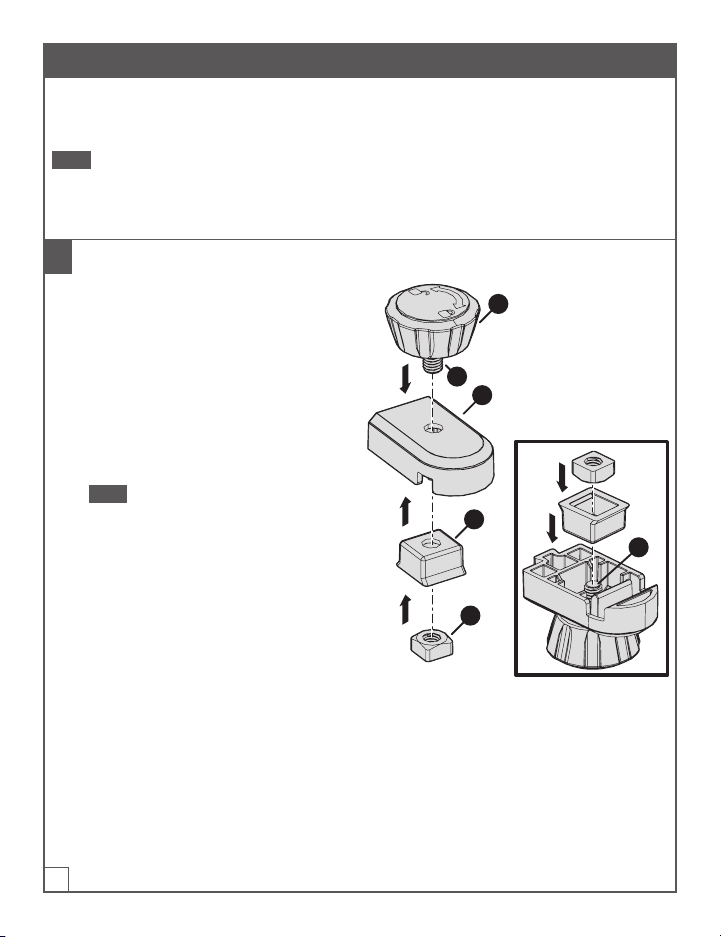
1 Assemble the Adjustable Stop Base
a. Insert the screw (1) of the adjustable
stop knob (G) into the hole on top of the
adjustable stop base (H).
b. Holding the adjustable stop knob (G) in
position, turn the adjustable stop base
(H) upside down so that the screw (1)
extends upward.
c. Drop the adjustable stop base wedge (I)
onto the screw (1) with the anged side
of the adjustable stop base wedge (I)
facing up.
Note The adjustable stop base wedge(I)
should sit ush with the adjustable stop
base (H). If it does not sit ush, rotate
the adjustable stop base wedge (I)
90degrees.
d. Place the adjustable stop square nut
(J) onto the screw (1); then rotate
the adjustable stop knob (G) until
the adjustable stop square nut (J) is
nger-tight.
G
H
1
I
1
J
Table of contents
Languages:


