Kremlin-Rexson VOLUREX User manual

INSTRUCTION MANUAL
VOLUREX PROPORTIONING GUN
PARVEX MOTOR - HARTING PLUG
Proportioning system
with outlet valve
25 cc # 105 824 0408
50 cc # 105 435 0408
100 cc # 105 145 0408
150 cc # 104 115 0408
Proportioning system
with outlet flange
25 cc # 105 824 0208
50 cc # 105 435 0208
100 cc # 105 145 0208
150 cc # 104 115 0208
Manual : 574.331.112 - 1210
Date : 03/10/12 - Supersede : 15/07/09
Modif.: Update
TRANSLATION OF THE ORIGINAL MANUAL
IMPORTANT : Before assembly and start-up, please read and clearly understand all the documents
relating to this equipment (professional use only).
THE PICTURES AND DRAWINGS ARE NON CONTRACTUAL. WE RESERVE THE RIGHT TO MAKE CHANGES WITHOUT PRIOR NOTICE.
KREMLIN - REXSON
l
150, avenue de Stalingrad
93 245 - STAINS CEDEX – France
: 33 (0)1 49 40 25 25 Fax : 33 (0)1 48 26 07 16
www.kremlin-rexson.com

KREMLIN REXSON 1 Manual : 574.331.112
INSTRUCTION MANUAL
VOLUREX PROPORTIONING GUN
TABLE OF CONTENTS
01. WARRANTY.......................................................................................................................................................... 2
02. SAFETY INSTRUCTIONS ..................................................................................................................................... 3
03. DESCRIPTION ...................................................................................................................................................... 6
04. OPERATING PRINCIPLE...................................................................................................................................... 7
05. TECHNICAL FEATURES...................................................................................................................................... 8
06. INSTALLATION .................................................................................................................................................. 11
07. MAINTENANCE .................................................................................................................................................. 11
08. TROUBLESHOOTINGS ...................................................................................................................................... 12
09. DISASSEMBLY - ASSEMBLY ............................................................................................................................ 12
10. ELECTRIC DIAGRAM......................................................................................................................................... 20
11. PNEUMATIC DIAGRAM...................................................................................................................................... 22
ADDITIONAL DOCUMENTATIONS :
Volurex proportioning system - Spare parts Doc. 574.331.120
Inlet valve Doc. 574.059.110
Proportioning part Doc. 574.045.110
Outlet valve Doc. 574.159.110

KREMLIN REXSON 2 Manual : 574.331.112
Dear Customer,
You are the owner of our new equipment and we would like to take this opportunity to thank you.
To make sure your investment will provide full satisfaction, special care has been taken by KREMLIN
REXSON during all designing and manufacturing processes.
To obtain the best result, safe and efficient operation of your equipment, we advice you to read and make
yourself familiar with this instruction and service manual. Indeed, the non-compliance with instructions and
precautions stated in this manual could reduce the equipment working life, result in operating trouble and
create unsafe conditions
01. WARRANTY
We reserve the right to make changes; these changes may be carried out after the receipt of the order. No claim
will be accepted as a consequence of any change carried out in the instruction manuals or in the selection guides.
Our equipment is checked and tested prior to shipment. In the case of a problem arising with the equipment, this
must be in writing, within ten days from the delivery date.
KREMLIN REXSON warrants all equipment manufactured bearing its name, to be free from defect in material or
workmanship for a period of 12 months (one shift per day or 1800 hours - 1 term reached) from the date of
delivery. Work life is based on single shift working - 8 hours per day. Warranty claims for defective items will only
be accepted in writing and will be verified and confirmed by us.
The warranty does not cover fair wear and tear, damage or wear caused by misuse, improper maintenance or
non-observance of our recommendations.
KREMLIN REXSON will repair or replace parts (carriage paid to our plant and accepted as defective by us). We
shall not be liable for any losses, resulting from a production breakdown. Upon request, we can carry out service
work at your premises; all expenses (travelling and accommodation) for KREMLIN REXSON technicians will be
chargeable.
In the event that it is found that equipment has been tampered with, this will invalidate the warranty. Equipment
that it is bought in will be subject to the suppliers' warranty.

KREMLIN REXSON 3 Manual : 574.331.112
02. SAFETY INSTRUCTIONS
GENERAL SAFETY INSTRUCTIONS
CAUTION : The equipment can be dangerous if you do not use it according to
the rules mentioned in this instruction manual. Read carefully all the
instructions hereafter before operating your equipment.
Only trained operators can use the equipment. (To acquire an essential training, please contact the
"KREMLIN REXSON University" training center - Stains).
The foreman must ensure that the operator has perfectly taken in the safety instructions of this equipment
as well as the instructions in the manuals of the different parts and accessories.
Read carefully all instruction manuals, label markings before operating the equipment.
Incorrect use may result in injury. This equipment is for professional use only. It must be used only for what
it has been designed for.
Guards (air motor cover, coupling shields, housings,…) have been designed for a safe
use of the equipment.
The manufacturer will not be held responsible for bodily injury or failure and / or damage to
property due to removal or partial removal of the guards.
Never modify the equipment. The parts and accessories supplied must be regularly inspected. Defective or
worn parts must be replaced.
Never exceed the equipment components' maximum working pressure.
Comply with regulations concerning safety, fire risks, electricity in force in the country of final destination of
the material. Use only products or solvent compatible with the parts in contact with the material (refer to
data sheet of the material manufacturer).
PICTOGRAMS
ADFECG
NIP HAZARD WARNING
MOVING
ELEVATOR
WARNING
MOVING PARTS
WARNING
MOVING
SHOVEL
DO NOT
EXCEED THIS
PRESSURE
HIGH PRESSURE
HAZARD
HJLKMQ
RELIEF OR
DRAIN VALVE
WARNING HOSE
UNDER
PRESSURE
WEAR GLASSES
OBLIGATORY
WEAR OF
GLOVES IS
OBLIGATORY
PRODUCT
VAPOR
HAZARDS
WARNING HOT
PARTS OR AREAS
NPR
ELECTRICAL
HAZARD WARNING FIRE
HAZARDS EXPLOSION
HAZARDS GROUNDING WARNING
(USER)
WARNING
SERIOUS
INJURIES

KREMLIN REXSON 4 Manual : 574.331.112
PRESSURE HAZARDS
Current legislation requires that an air relief shut off valve is mounted on the supply circuit of the
pump motor to let air off when closing the supply circuit. Without this precaution, the motor residual
air of the motor may let the pump beat and cause a serious injury.
Please ensure that, a material drain valve is mounted on the material circuit to drain it (after
shutting down air to the motor and the pressure relief) before any servicing on the equipment. These
valves must be closed for air and opened for product when processing.
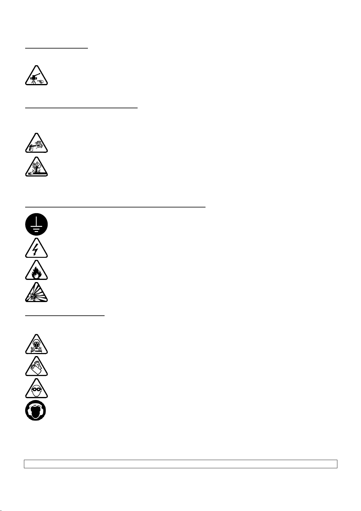
HIGH PRESSURE INJECTION HAZARDS
When working with high pressure equipment, special care is required. Fluid leaks can occur. Then
there are injection risks in exposed parts of body that may cause severe injuries or amputations :
Medical care must be handled immediately if product is injected under the skin or in other
parts of the body (eyes, fingers).
Never point the spray gun at any one. Never try to stop the spray with your hands or fingers
nor with rags or similars.
Follow the shut down procedure and always depressurize air and fluid circuits before
carrying out any servicing on the gun (cleaning, checking, maintenance of the material or
cleaning of the gun nozzles).
For the guns equipped with a safety device, always lock the trigger when you do not start the
gun.
FIRE - EXPLOSION - SPARKS - STATIC ELECTRICITY HAZARDS
A poor earth connection, inadequate ventilation, sparks or static electricity can cause an explosion
or fire. to avoid these risks when using or servicing KREMLIN REXSON equipment, the following
safety procedures must be followed :
ensure a good earth connection and ground the parts to be handled i.e. solvents, materials,
components and equipment,
ensure adequate ventilation,
keep working area clean and free from waste solvents, chemicals, or solid waste i.e. rags,
paper and empty chemicals drums,
never use electrical switches / power if in an atmosphere of volatile solvent vapour,
stop working immediately in case of electrical arcs,
never store chemicals and solvents in the working area.
TOXIC PRODUCT HAZARDS
Toxic products or vapours can cause severe injury not only though contact with the body, but also if
the products are ingested or inhaled. It is imperative :
to know the material products and their risks,
notified or hazardous materials must be stored in accordance with the regulations,
the material must be stored in an appropriate container, never place materials in a container
where there is a risk o spillage or leakage,
a procedure must be applied for the safe disposal of waste material. It must comply with all
prevailing regulations and legislations of the country where the equipment is to be used,
protective clothing should always be worn in compliance with the material manufacturers'
recommendations,
depending on the application and chemical safety instructions, safety glasses, hearing
protective earplug, gloves, foot wear, protective masks and possible breathing equipment
should be worn to comply with the regulations
(Refer to chapter "Safety equipment of KREMLIN selection guide).

KREMLIN REXSON 5 Manual : 574.331.112
CAUTION!
It is forbidden using any solvent or with halogenated hydrocarbon base and also products with
these solvents facing aluminium or zinc. The non-compliance with the instructions may cause
explosion hazards causing serious or fatal injuries.
EQUIPMENT REQUIREMENTS
Guards (air motor cover, coupling shields, housings,…) have been designed for a safe
use of the equipment.
The manufacturer will not be held responsible for bodily injury or failure and / or damage
to property due to removal or partial removal of the guards.
PUMP
Before carrying out any work, it is imperative to get used with the compatibilities of motors with
pumps before coupling. The operator shall understand the equipment and the safety instructions.
These instructions are available in the manuals of the pumps.
F
A
The air motor is designed to be mounted with a pump. Never modify any components or couplings.
Where operating, please keep hands away from moving parts. Before starting up the equipment,
please read the PRESSURE RELIEF instructions. Please ensure that any relief or drain valves
fitted are in good working order.
HOSES
Keep hoses out of circulation areas, moving parts or hot surfaces,
Never expose product hoses to temperature higher than + 60°C / 140° F or lower than 0°C /
32° F,
Never pull or use the hoses to move the equipment,
Tighten all fittings as well as the hoses before operating the equipment,
Check the hoses regularly; change them if they are damaged,
Never exceed the maximum working pressure (MWP) indicated on the hose.
USED PRODUCTS
Considering the variety of products that may be used by the users and the impossibility to check off all
chemical data, of possible reactions of chemicals to each other and their long term evolution,
KREMLIN REXSON can not be considered as liable for :
the bad compatibility of wetted parts,
risks for staff and surroundings,
for worn or out of order parts, for wrong working of equipments or units, as well as for the
qualities of final product.
The user must know and prevent the possible risks as toxic vapours, fires or explosions due to used
products. He shall determine the risks of immediate reactions or pursuant to repeated exposures of the
staff.
KREMLIN REXSON shall not be liable for psychic injuries, direct or indirect material damages further to
the use of chemicals.

KREMLIN REXSON 6 Manual : 574.331.112
ENVIRONMENT
Label marking on the Volurex
proportioning system
This equipment consists of a label plate with the name of the manufacturer, the
equipment part number, the interesting informations to use correctly the equipment
(pressure, voltage…) and the above pictogram.
The equipment is designed with and consists of high quality materials and
components which can be re-used.
The 2002/96/EC European Directive covers all equipments with a crossed-out bin
pictogram. Please inform yourself about the collection systems for electric and
electronic equipments.
Please according to local rules and do not throw the old equipments with
household wastes. A correct disposal of the old equipment will help prevent
negative consequences for the environment and health.
03. DESCRIPTION
The VOLUREX system consists of a Volurex proportioning gun and a control bay. It is designed for dispensing
materials beads (silicone, adhesive, mastic…) for cold and hot extrusion.
The VOLUREX assembly is linked to a robot that ensures the displacement of the proportioning system (or of
the part). The robot sends a signal to the control bay, thus providing the flow rate required to dispense the
bead.
The flow rate as well as the dosing are programmable and electronically controlled thanks to the control bay.
Depending upon the external informations (robot, manipulator, proportioning system), the bay drives the
system. It controls some safety devices that protect the proportioning system and its environment.

KREMLIN REXSON 7 Manual : 574.331.112
04. OPERATING PRINCIPLE
The proportioning system consists of :
The dispensing system consists of 3 actuators :
- The motor (6) of the proportioning system gives a translation motion to the piston (4) via the ball screw (5)
- The electrovalve (1a) enables the material coming from the fluid inlet (2) to enter into the chamber.
- The electrovalve (1b) enables the material from the chamber (3) to be extruded via the fluid outlet (7).
OPERATING
First position :
-The piston (4) is downwards and the ball screw (5) upwards.
Filling :
- The filling electrovalve (1a) opens to let the material enter in via the fluid inlet (2).
-The fluid enters in the chamber (3) via the shutting group (not represented).
- The piston (4) goes up because of the fluid pressure until coming into contact with the ball screw (5).

KREMLIN REXSON 8 Manual : 574.331.112
Pressurization :
- Thanks to the pressure sensor (8), the piston (4) goes down to put the fluid to the required pressure.
Extrusion :
- The extrusion electrovalve (1b) opens to let the material enter in via the fluid outlet (7).
- The piston (4) goes down in the chamber (3) with a speed that fits in with the output selected by the robot.
- The volume applicated is calculated thanks to the stroke carried out by the piston (4).
Drain :
The drain consists in :
- carry out an extrusion (empty the gun chamber) during a long duration shutdown of the proportioning
system or during a request of the operator.
- then carry out a filling operation (fill the gun chamber with material).
05. TECHNICAL FEATURES
FEATURES
The VOLUREX can apply materials which have viscosities from 2 000 up to 1 000 000 Cps.
VOLUREX
Features 25 cc 50 cc 100 cc 150 cc
Capacity (cm3) 25 50 100 150
Maxi fluid output (cm3/mn) 195 362 726 1090
Fluid application Hot extrusion
Maximum inlet fluid pressure 200 bar / 2900 psi
Outlet pressure 200 bar
/ 2900 psi 170 bar
/ 2465.5 psi 85 bar
/ 1233 psi 60 bar
/ 870 psi
Air pressure (valve) 6 bar / 87 psi
Motorization version Parvex
Pressure sensor 0-200 bar / 0 - 2900 psi 4-20 mA
Maximum fluid temperature 80°C / 176° F
Weight (kg) 12 kg / 26.4 lbs 12 kg / 26.4 lbs 13 kg / 28.6 lbs 13 kg / 28.6 lbs
Fluid connections
Fluid inlet (inlet valve) 3/4" Rp
Fluid outlet Refer to 'Specific features of the proportioning system'
Electric features
Voltage (V) 230
Power (W) 515 515 555 575
Intensity (A) 2.4 2.4 2.5 2.5
Frequency (Hz) 50
Electric connectors
Connectors Harting
Electric resistances 3 resistances of 125W - 230V
(1 inlet valve, 1 outlet valve / outlet flange,
1proportioning system body)
Heated collar (proportioning part) 140 W 140 W 160 W 160 W
Temperature drill PT 100 (located in the proportioning system body)

KREMLIN REXSON 9 Manual : 574.331.112
Specific features of the proportioning system with outlet valve
Fluid connections
Fluid outlet (outlet valve) Threading, model F10x100
Nozzle (option) Ø 0.8 to 8
Specific features of the proportioning system with outlet flange
Fluid connections
Fluid outlet (outlet valve) 1/2" Rc
DIMENSIONS OF THE VOLUREX WITH OUTLET VALVE
119 84 209
166
88
60
99
140
179
32.4
632
596
120
20244
224194
673
24
78

KREMLIN REXSON 10 Manual : 574.331.112
DIMENSIONS OF THE VOLUREX WITH OUTLET FLANGE
209
40
64
80 60 12
61 105 120
20
540
1/2" Rc
SORTIE
3/4" Rp
ENTREE
2 vis CHc M6
2 pions de centrage
8 h11
OUTLET
INLET
2 CHc M6 screws
2 Ø 8h11 centering
pins

KREMLIN REXSON 11 Manual : 574.331.112
06. INSTALLATION
PNEUMATIC CONNECTIONS
Install a HP fluid hose between the mastic regulator fluid outlet and the VOLUREX proportioning system
inlet valve. The hose can be a heated one to make easier the fluid flow.
Install an air hose (4x6) to supply with compressed air the proportioning system. Connect it to the
compressed air network by means of a regulator.
ELECTRIC CONNECTIONS
Connect the electric cables between the control bay and the proportioning system.
Connect the interface electric cables between the control bay and the robot control box.
Connect the control bay to the network.
07. MAINTENANCE
Guards (air motor cover, coupling shields, housings,…) have been designed for a safe
use of the equipment.
The manufacturer will not be held responsible for bodily injury or failure and / or damage to
property due to removal or partial removal of the guards.
DAILY PREVENTIVE MAINTENANCE
Be certain the hoses are in good condition and that there is no leakage.
Drain the proportioning gun after a long duration shutdown.
Check the nozzle is clean and correctly tightened. Clean it or change it (clogging or bead fault).
MONTHLY PREVENTIVE MAINTENANCE
Check if there is air or fluid leakage at the inlet and outlet valves' level (fluid leakage detector).
Lubricate the ball screw (every 300
hours))
(KLUBER grease - P.N°. STABUTHERM GH 461)
(ball screw duration life : 500 000 cycles)
NEVER TAKE OFF THE BALL SCREW
FROM THE NUT.
Lubricate the needle stop
(KLUBER grease - P.N°. STABUTHERM GH 461)
2 lubricators (one located on the nut of the ball
screw, the other one located on the gear box)
enable to grease the ball screw as well as the
needle stop. Take off the carter to carry out the
lubrication.

KREMLIN REXSON 12 Manual : 574.331.112
BIMONTHLY PREVENTIVE MAINTENANCE
Check the tightening :
- of the inlet valve on the body,
- of the outlet valve or flange on the body.
Check there is no fluid leak coming from the piston of the proportioning part.
YEARLY PREVENTIVE MAINTENANCE
Remove, clean the inlet valve. Change the seals.
Remove, clean the outlet valve. Change the seals.
Remove, clean the proportiong part. Change the seals.
Check the piston.
Check the ball screw and the bearings.
When reassembling :
Lubricate the ball screw, the needle stop, the slides and the bearings (KLUBER
grease - STABUTHERM GH 461)
Lubricate the seals, the piston, the cylinder, the needle with PTFE MAGNALUBE
grease.
Nota : if using intensively the equipment, the maintenance frequency could be modified.
08. TROUBLESHOOTINGS
If a trouble occurs during the operating of the VOLUREX proportioning system, the fault will be displayed on the
bay display unit (refer to bay instruction manual).
09. DISASSEMBLY - ASSEMBLY
Guards (air motor cover, coupling shields, housings,…) have been designed for a safe
use of the equipment.
The manufacturer will not be held responsible for bodily injury or failure and / or damage to
property due to removal or partial removal of the guards.
DISASSEMBLY / ASSEMBLY OF THE COMPLETE PROPORTIONING SYSTEM
Disassembly :
Empty completely the proportioning system,
Shut off the air supply of the pump into operation,
Switch the 'AUTO-MANU' control box switch on 'MANU',
Drain the proportioning system,
Open the drain valve (pump or collector),
Switch off the proportioning system,
Disconnect the beads of the electric connection,
Remove the VOLUREX proportioning gun.
Assembly :
Install the new proportioning system,
Connect the fluid supply hose on the inlet valve,
Connect all the electric connectors,

KREMLIN REXSON 13 Manual : 574.331.112
Switch on the heat area,
Close the drain valve (pump or collector),
Install air on the pump motor,
Drain the circuit (pump, hose, proportioning system) until there is no more air,
Switch the 'AUTO MANU' control box switch on 'AUTO'.
To remove a component from the proportioning system, you must :
- Stop the installation (depressurize, drain),
- Shut off the electric and pneumatic supply,
- Take off the 2 carters.
CHANGING THE INLET VALVE
Remove the hose located upwards the inlet valve,
Disconnect the 2 air hoses (red and blue),
Unscrew the 4 screws that hold the inlet valve on the proportioning system (BTR wrench n° 5).
Take off the inlet valve.
On the new valve, lubricate the seal in contact with the body of the proportioning system,
Install the new valve, slide it on the heated resistance, then tighten the 4 screws.
Install the fluid supply hose and the air hoses.
Red hose top fitting (closing of the valve)
Blue hose low fitting (opening of the valve)
Place the installation into operation.
To disassemble / assemble the valve, refer to 'INLET VALVE' documentation.
CHANGING OF THE OUTLET VALVE
Disconnect the 2 air hoses (red and blue).
Unscrew the 4 screws that hold the outlet valve on the proportioning system (BTR wrench n° 5).
Remove the outlet valve.
On the new valve, lubricate the seals in contact with the proportioning system.
Install the new valve, make the heated resistance slide on the hole expected (shoulder hole, model Ø 5 mm
/ 0.2"), then tighten the 4 screws.
Connect the air hoses.
Red hose low fitting (closing of the valve)
Blue hose top fitting (opening of the valve)
Place the installation into operation.
To disassemble / assemble the valve, refer to 'OUTLET VALVE' documentation.

KREMLIN REXSON 14 Manual : 574.331.112
DISASSEMBLY / ASSEMBLY OF THE PROPORTIONING PART
Remove the inlet valve and the outlet valve
of the proportioning system or the outlet
flange.
Disconnect the pressure sensor (10).
Unscrew the screws (13) (BTR wrench n° 5)
and screw the 2 extractions screws (14)
(BTR wrench n° 3).
Remove the electric box (20).
Take off the resistances (27) and the
temperature drill (23) located on the
proportioning body unscrewing the screw of
the thimble rope (BTR wrench n° 3).
Unscrew the 2 screws (8) that hold the fixing
plate (6) and the proportioning body (C)
(BTR wrench n° 4).
10+11+12+15+16
9
C
27
25+26
23+24
20+21+22+23
13
14

KREMLIN REXSON 15 Manual : 574.331.112
Detail of the piston seals
On the proportioning part :
Unscrew the little screw (10) located on the middle
of the heated collar (12).
Take off the 4 screws (8) that hold the proportioning
part.
Make the body (7), the cylinder (5), the piston
assembly slide downwards.
Leave the sleeve (11) and the heated collar (12).
Take off the piston and change the seals (2, 14).
Assembly :
Lubricate the seals (2, 9, 14) and the seal (8A) for
the 25 cc Volurex proportioning system.
On the piston (1), locate the seal (14), a seal (2),
the ring (13), the second seal (2), the stop washer
(3) - refer to drawing above.
Applicate Loctite 577glue on the threading of the
screw (4) and tighten the whole with that screw.
Grease the inside of the cylinder (5) and install the
piston assembly into that cylinder.
Important : Make it slide from downwards to
upwards to prevent from damaging the seals of
the piston.
Install the counter plate (6).
Caution when mounting the plate (5)
shoulder downwards.
Install the seals (9 and 8A) at the bottom of the
cylinder (5).
Slide the whole in the sleeve (11).
Applicate Loctite 222 glue on the screw (10).
Fix the whole (11 & 12) on the cylinders (5) with the
screw (10).
Reinstall the body (7) at the bottom of the cylinder
(5).
(Locate the 2 holes of the body in front of the 2
holes of the fixing plate (33)).
Tighten the screws (8) in the 4 tie-rods (ind. 18 of
the fixing part).
Connect the heated collar.
Reinstall the different components : the junction
box, the pressure sensor, the inlet valve and the
outlet valve.
Place the installation into operation.

KREMLIN REXSON 16 Manual : 574.331.112
CHANGING THE MOTOR
Stop the installation (Depressurize, drain, disconnect).
Disconnect the 2 cables connected to the motor (power
and control).
Unscrew the 4 screws (47) that hold the motor (48) (BTR
wrench n° 4).
Take off the motor.
Remove the motor pinion (39) taking off the screw (41)
(BTR wrench n° 3) and the plate (40) on which it is fixed.
Install a new motor and connect the 2 cables.
Place the installation into operation.
CHANGING THE BALL SCREW (32)
Remove the inlet valve, the outlet valve or outlet flange,
the proportioning part (do not remove the sleeve and the
heated collar).
Unscrew the 2 screws (77) (BTR wrench n° 2.5) installed
on the strap (84).
Unscrew the 4 screws (31) (BTR wrench n° 5) installed on
the stop (30).
Hold the assembly to prevent it from rotating.
Take off the ball screw downwards.
When disassembling, check if there is a play in the
bearings.
Lubricate the ball screw
(KLUBER grease - STABUTHERM GH 461)
NEVER TAKE OFF THE BALL SCREW FROM THE
NUT.
Install the new ball screw, the stop (30). Tighten them with
the screws (77 and 31).
Reinstall the proportioning part, the outlet valve or the
outlet flange and the inlet valve.
32
30+31
35+36+37
41
40
39
42+43
38
3
3
3
4
44
CHANGING THE STOP ASSEMBLY, THE BALL BEARINGS (35)
Take off the 4 tie-rods (9).
Take off the screws (8) that hold the
bearing box (101) on the fixing plate (6).
Change the assembly (35).
The assembly (35) consists of the
bearing box, the ball bearing (104), the
needle stop (110), the spacers (106,
112), the washers (105, 111), the gear
shaft (108), the circlips (107).
Nota : the pinion (38) does not belong to
the assembly (35).
101
104
113
111
109
107
114
103
112
106
110
105
102
108
38
48
47

KREMLIN REXSON 17 Manual : 574.331.112
Disassemble the receptor pinion (38) from the bearing box.
Unscrew the 2 screws (43) (BTR wrench n° 4); you can thus remove the washer (42).
Take off the 2 pins, the pinion (38).
Change the assembly (35). Reinstall the receptor pinion (38), the 2 pins (44), the washer (42) and the 2
screws (43).
Caution : comply with the assembly order of the pinion and washer.
Lubricate the bearings, the needle stop by means of the lubricator (113).
Locate the new assembly on the proportioning system.
Make the assembly rotate manually before carrying on the assembly of the other components (tie-rod, ball
screw…).
CHANGING THE POM SENSOR (61)
48
91+92+93+94+95
58
54
46+47
45
67
70
66
62
68
65
55
49
56+57+59
61+63
74
72+73
60
76
Remove the connection plate (65) unscrewing the screws (67)
Unscrew the screws (63) from the sensor. Remove the electric thimbles.
Take off the sensor (61).
Install a new sensor instead of it.
Connect the electric rope thimbles (terminals 1 and 2).

KREMLIN REXSON 18 Manual : 574.331.112
CHANGING THE MEASURE ROD (34)
Remove the sensor support (62)
Unscrew the screws to take off the 2 spacers (55).
Unscrew the 2 screws (49) (BTR wrench n° 4).
Take off the slide (54), opposite side from the cable support.
Take off the strap (84) and the detection rod (34).
You can change the little bearings (81) taking off the clips (82).
Lubricate the bearings during the assembly.
85
96
80+81+82
84
90
88
75
89
87
86
77
34
To change the rod (34) :
Unscrew the screws (90).
Take off the plate (89), the spring (87).
Unscrew the nut (86).
The rod is screwed in the detection ring (75).
During the assembly, comply with the 214 mm / 8.4" dimension between
the end of the rod (34) and the detection ring (75). (refer to drawing).
Applicate glue on the threading of the rod (Loctite 577).
Reinstall the nut (86), the spring (87), the plate (89), the 2 screws (90).

KREMLIN REXSON 19 Manual : 574.331.112
Check the 5 mm / 0.2"
dimension between the
screw (85) and the plate
(89).
Lubricate the slides (54).
Reinstall the slides and the
cart (rod with plate).
Tighten the screws
manually.
Place the cart downwards
and tighten the low part of
the slides with a clamps.
Tighten the screws with the
wrench.
Install on the top the plate (65) with the connectors.
Move the clamp to the top of the slides and tighten the upper screws.
Move the cart checking if the bearings run.
Lubricate the rod (34) and reinstall the ball screw (32).
Install it in the strap (84).
Line up the different parts.
Install the plate (30) on the lower part of the ball screw and fix it with the screws (31).
Reinstall the proportioning part, the outlet valve and the inlet valve.
CHANGING THE ELECTROVALVES (91)
Disconnect the electrovalves.
Change them.
EV (91G) that controls the inlet valve is towards the outside.
EV (91E) that controls the outlet valve is towards the inside.
91G
54
45
49
74
72+73
76
91E
This manual suits for next models
8
Table of contents
Popular Dispenser manuals by other brands

Safety 1st
Safety 1st Ready! Growing Baby Nursery Kit quick start guide

Aike
Aike AK1205 user manual

CBS
CBS B822 Series COMPONENT MAINTENANCE MANUAL WITH ILLUSTRATED PARTS LIST

TEFAL
TEFAL BR3019U manual

Remcor
Remcor Cornelius VANGUARD 245 Installation & service manual

Nordson
Nordson UltimusPlus Connection instructions

Nordson
Nordson FoamMelt 200 Operator card

Air Delights
Air Delights MICROBURST 9000 quick start guide

Saraya
Saraya GUD-1000A instruction manual

Follett
Follett Chewblet 7 Series Installation, operation and service manual

Nordson ASYMTEK
Nordson ASYMTEK DispenseJet Series owner's manual

Techfood
Techfood Manual Nutella Dispenser Original instructions