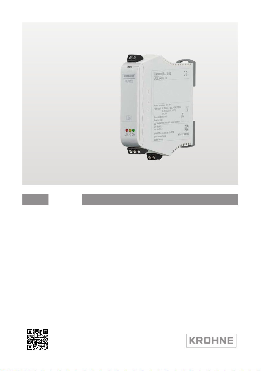
KROHNE SU 502 User manual

SU 502 Handbook

2
Contents
SU 502 •
66134-EN-220412
Contents
1 About this document ............................................................................................................... 4
1.1 Function ........................................................................................................................... 4
1.2 Target group ..................................................................................................................... 4
1.3 Symbols used................................................................................................................... 4
2 For your safety ......................................................................................................................... 5
2.1 Authorised personnel ....................................................................................................... 5
2.2 Appropriate use................................................................................................................ 5
2.3 Warning about incorrect use............................................................................................. 5
2.4 General safety instructions............................................................................................... 5
2.5 Installation and operation in the USA and Canada ........................................................... 5
2.6 Safety instructions for Ex areas........................................................................................ 6
3 Product description ................................................................................................................. 7
3.1 Conguration.................................................................................................................... 7
3.2 Principle of operation........................................................................................................ 7
3.3 Adjustment ....................................................................................................................... 7
3.4 Packaging, transport and storage..................................................................................... 7
4 Mounting................................................................................................................................... 9
4.1 General instructions ......................................................................................................... 9
5 Connecting to power supply................................................................................................. 10
5.1 Preparing the connection ............................................................................................... 10
5.2 Connection procedure.................................................................................................... 11
5.3 Wiring plan ..................................................................................................................... 11
6 Setup ....................................................................................................................................... 13
6.1 Adjustment system......................................................................................................... 13
6.2 Adjustment elements...................................................................................................... 13
6.3 Automatic function test................................................................................................... 15
6.4 Function table "Point level" ............................................................................................. 17
7 Diagnostics and servicing .................................................................................................... 19
7.1 Maintenance .................................................................................................................. 19
7.2 Rectify faults................................................................................................................... 19
7.3 Diagnosis, fault messages ............................................................................................. 19
7.4 How to proceed if a repair is necessary.......................................................................... 20
8 Dismount................................................................................................................................. 21
8.1 Dismounting steps.......................................................................................................... 21
8.2 Disposal ......................................................................................................................... 21
9 Certicatesandapprovals.................................................................................................... 22
9.1 Approvals for Ex areas ................................................................................................... 22
9.2 EU conformity................................................................................................................. 22
9.3 SIL conformity (optional) ................................................................................................ 22
10 Supplement ............................................................................................................................ 23
10.1 Technical data ................................................................................................................ 23
10.2 Dimensions .................................................................................................................... 25
10.3 Trademark ...................................................................................................................... 26

3
Contents
SU 502 •
66134-EN-220412
Supplementary documentation
Information:
Supplementary documents appropriate to the ordered version come
withthedelivery.Youcanndthemlistedinchapter"Product descrip-
tion".
Editing status: 2022-04-06

4
1 About this document
SU 502 •
66134-EN-220412
1 About this document
1.1 Function
This instruction provides all the information you need for mounting,
connection and setup as well as important instructions for mainte-
nance,faultrectication,theexchangeofpartsandthesafetyofthe
user. Please read this information before putting the instrument into
operation and keep this manual accessible in the immediate vicinity
of the device.
1.2 Target group
This operating instructions manual is directed to trained personnel.
Thecontentsofthismanualmustbemadeavailabletothequalied
personnel and implemented.
1.3 Symbols used
Information, note, tip: This symbol indicates helpful additional infor-
mation and tips for successful work.
Note: This symbol indicates notes to prevent failures, malfunctions,
damage to devices or plants.
Caution: Non-observance of the information marked with this symbol
may result in personal injury.
Warning: Non-observance of the information marked with this symbol
may result in serious or fatal personal injury.
Danger: Non-observance of the information marked with this symbol
results in serious or fatal personal injury.
Ex applications
This symbol indicates special instructions for Ex applications.
• List
The dot set in front indicates a list with no implied sequence.
1 Sequence of actions
Numbers set in front indicate successive steps in a procedure.
Disposal
This symbol indicates special instructions for disposal.

5
2 For your safety
SU 502 •
66134-EN-220412
2 For your safety
2.1 Authorised personnel
All operations described in this documentation must be carried out
onlybytrained,qualiedpersonnelauthorisedbytheplantoperator.
During work on and with the device, the required personal protective
equipment must always be worn.
2.2 Appropriate use
SU 502 is a universal controller for connection of level switches.
Youcannddetailedinformationabouttheareaofapplicationin
chapter " Product description".
Operational reliability is ensured only if the instrument is properly
usedaccordingtothespecicationsintheoperatinginstructions
manual as well as possible supplementary instructions.
2.3 Warning about incorrect use
Inappropriate or incorrect use of this product can give rise to applica-
tion-specichazards,e.g.vesseloverllthroughincorrectmounting
or adjustment. Damage to property and persons or environmental
contamination can result. Also, the protective characteristics of the
instrument can be impaired.
2.4 General safety instructions
This is a state-of-the-art instrument complying with all prevailing
regulations and directives.The instrument must only be operated in a
technicallyawlessandreliablecondition.Theoperatorisresponsi-
ble for the trouble-free operation of the instrument. When measuring
aggressive or corrosive media that can cause a dangerous situation
if the instrument malfunctions, the operator has to implement suitable
measures to make sure the instrument is functioning properly.
The safety instructions in this operating instructions manual, the na-
tional installation standards as well as the valid safety regulations and
accident prevention rules must be observed by the user.
For safety and warranty reasons, any invasive work on the device
beyond that described in the operating instructions manual may be
carried out only by personnel authorised by the manufacturer. Arbi-
traryconversionsormodicationsareexplicitlyforbidden.Forsafety
reasons,onlytheaccessoryspeciedbythemanufacturermustbe
used.
To avoid any danger, the safety approval markings and safety tips on
the device must also be observed.
2.5 Installation and operation in the USA and
Canada
This information is only valid for USA and Canada. Hence the follow-
ing text is only available in the English language.

6
2 For your safety
SU 502 •
66134-EN-220412
Installations in the US shall comply with the relevant requirements of
the National Electrical Code (ANSI/NFPA 70).
Installations in Canada shall comply with the relevant requirements of
the Canadian Electrical Code.
2.6 Safety instructions for Ex areas
For applications in explosion-proof areas (Ex), only devices with cor-
respondingExapprovalmaybeused.ObservetheEx-specicsafety
instructions.These are an integral part of the operating instructions
and are enclosed with every device with Ex approval.

7
3 Product description
SU 502 •
66134-EN-220412
3 Product description
3.1 Conguration
The scope of delivery encompasses:
• Controller SU 502
• Documentation
– This operating instructions manual
– Ex-specic"Safety instructions" (with Ex version)
– Safety Manual "Functional safety (SIL) acc. to IEC 61508" (with
SIL version)
– Ifnecessary,furthercerticates
Thetypelabelcontainsthemostimportantdataforidenticationand
use of the instrument:
• Instrument type
• Information about approvals
• Technical data
• Serial number of the instrument
• Manufacturer information
3.2 Principle of operation
The SU 502 is a single channel controller for level detection of limit
switches with 8/16 mA interface. Via the integrated relay simple con-
trol tasks can be solved. Typical applications are monitoring functions
suchasoverllordryrunprotection,Optionallyanadditionalsecond
relay can be ordered.Via a DIL switch the function of the second
relaycanbedetermined.Itcanbeconguredasfailsaferelayoras
second level relay.
The SU 502 controller powers connected sensors and simultaneously
processes their measuring signals.
When the medium reaches the switching point of the sensor, the
sensor current changes.This is measured and evaluated by SU 502.
The change causes the output relays to switch according to the set
operating mode.
3.3 Adjustment
All adjustment elements are located under a hinged front plate. The
operating mode, switch-on pulse monitoring and the switching delay
can be set via a DIL switch block. In addition, the correct function of
the measuring system can be checked by simply pressing a key.
3.4 Packaging, transport and storage
Your instrument was protected by packaging during transport. Its
capacity to handle normal loads during transport is assured by a test
based on ISO 4180.
The packaging of standard instruments consists of environment-
friendly, recyclable cardboard. For special versions, PE foam or PE
Scope of delivery
T
ype label
Application area
Functional principle
Packaging

8
3 Product description
SU 502 •
66134-EN-220412
foil is also used. Dispose of the packaging material via specialised
recycling companies.
Transport must be carried out in due consideration of the notes on the
transport packaging. Nonobservance of these instructions can cause
damage to the device.
The delivery must be checked for completeness and possible transit
damage immediately at receipt. Ascertained transit damage or con-
cealed defects must be appropriately dealt with.
Up to the time of installation, the packages must be left closed and
stored according to the orientation and storage markings on the
outside.
Unless otherwise indicated, the packages must be stored only under
the following conditions:
• Not in the open
• Dry and dust free
• Not exposed to corrosive media
• Protected against solar radiation
• Avoiding mechanical shock and vibration
• Storage and transport temperature see chapter " Supplement -
Technical data - Ambient conditions"
• Relative humidity 20 … 85 %
Transport
Transport inspection
Storage
Storage and transport
temperature

9
4 Mounting
SU 502 •
66134-EN-220412
4 Mounting
4.1 General instructions
SU 502 is designed for carrier rail mounting (top hat rail 35 x 7.5 ac-
cording to DIN EN 50022/60715). Due to its protection rating of IP20,
the instrument is suitable for mounting in switching cabinets. It can be
mountedhorizontallyandvertically.
Note:
When several instruments are mounted together without space in
between, the ambient temperature at the installation location of the
instrument must not exceed 60 °C. Around the ventilation slots there
must be a distance of at least 2 cm to the next component.
SU 502 in Ex version is a corresponding, intrinsically safe instrument
andmustnotbeinstalledinhazardousareas.Asafeoperationisonly
ensurediftheoperatinginstructionsandEUtypeapprovalcerticate
are observed. SU 502 must not be opened.
A distance of 50 mm to the intrinsically safe terminals must be en-
sured when mounting.
The instrument is suitable for standard and extended ambient condi-
tions acc. to DIN/EN/IEC/ANSI/ISA/UL/CSA 61010-1.
Makesurethattheenvironmentalandambientconditionsspeciedin
chapter " Technical data" are maintained.
Mounting options
Ambient conditions

10
5 Connecting to power supply
SU 502 •
66134-EN-220412
5 Connecting to power supply
5.1 Preparing the connection
Always keep in mind the following safety instructions:
Warning:
Connect only in the complete absence of line voltage.
• Connect only in the complete absence of line voltage
• If overvoltage surges are expected, overvoltage arresters should
be installed
Note:
Install a disconnecting device for the instrument which is easy to
access.The disconnecting device must be marked for the instrument
(IEC/EN 61010).
Inhazardousareasyoumusttakenoteoftherespectiveregulations,
conformityandtypeapprovalcerticatesofthesensorsandpower
supply units.
Thedataforpowersupplyarespeciedinchapter"Technical data".
The voltage supply of SU 502 is connected with standard cable ac-
cording to the national installation standards.
The sensors are connected with standard two-wire cable without
shielding. If electromagnetic interference is expected which is above
the test values of EN 61326 for industrial areas, shielded cable should
be used.
Make sure that the cable used has the required temperature resist-
anceandresafetyformax.occurringambienttemperature
Connect the cable shielding on both ends to ground potential. In
the sensor, the shielding must be connected directly to the internal
ground terminal.The ground terminal on the outside of the sensor
housing must be connected to the potential equalisation (low imped-
ance).
If potential equalisation currents are expected, the connection on the
processing side must be made via a ceramic capacitor (e. g. 1 nF,
1500 V). The low-frequency potential equalisation currents are thus
suppressed,buttheprotectiveeectagainsthighfrequencyinterfer-
ence signals remains.
Take note of the corresponding installation regulations for Ex applica-
tions. In particular, make sure that no potential equalisation currents
owoverthecablescreen.Incaseofgroundingonbothsidesthis
can be achieved by the use of a capacitor or a separate potential
equalisation.
Safety instructions
Safety instructions
for Ex applications
Voltage supply
Connection cable
Cable screening and
grounding
Connection cable
for Ex applications

11
5 Connecting to power supply
SU 502 •
66134-EN-220412
5.2 Connection procedure
The pluggable terminals can be removed as needed to allow more
convenient connection. To make the electrical connection, proceed as
follows:
1. Mount the instrument as described in the previous chapter
2. Connect sensor cable to terminal 1/2, and where applicable, con-
nect the shielding
3. Connectswitched-opowersupplytoterminal16/17
4. Connect relay to terminal 10/11/12
5. Option with fail safe relay: Connect relay to terminal 13/14/15
Theelectricalconnectionisnished.
5.3 Wiring plan
1
2
4
3
13 14 15
10 11 12
-+
1 2
-+
16 17
OPEN
1 Sensor circuit (8/16 mA)
2 Relay output
3 Fail safe relay/second relay output (optional)
4 Voltage supply

12
5 Connecting to power supply
SU 502 •
66134-EN-220412
Information:
The connection terminals can be detached towards the front, if neces-
sary. This can be useful when working in tight spaces or for exchange
of an instrument.

13
6 Setup
SU 502 •
66134-EN-220412
6 Setup
6.1 Adjustment system
1
2
3
4
Fig. 1: Display and adjustment elements
1 Test key
2 DIL switch block
3 Signal lamps (LEDs)
4 Hinged front cover
6.2 Adjustment elements
Control lamps (LED) in the front plate indicate operation, switching
status and fault signal.
• Green
– Operating control lamp
– Mains voltage on, instrument is operating
• Red
– Fault indicator
– Fault on the sensor circuit due to sensor failure or line break
– The relay deenergises in case of failure
• Yellow
Control lamps

14
6 Setup
SU 502 •
66134-EN-220412
– Relay control lamp
– Lights with activated (current-carrying) relay status
The adjustment elements are located under a hinged front cover.To
open it, use a small screwdriver in conjunction with the slot on the
upper side of the front cover. To close it, push the cover at bottom and
toprmlyontothefrontcoveruntilyouhearthetworetainingclips
snap in.
The DIL switch block is located behind the front cover.The individual
switches are assigned as follows:
1
2
3
4
5
6
maxmin
0s
0s
0s
0s
7
2x
+2s
+6s
t
+2s
+6s
t
Fig. 2: DIL switch SU 502
1 Mode (min./max. adjustment)
2 Switch-onpulsemonitoringOn/O
3 Switch-on delay 2 seconds
4 Switch-on delay 6 seconds
5 Switch-odelay2seconds
6 Switch-odelay6seconds
7 Switchover, function relay 2 (optional)
The requested operating mode is set with the min./max. switch (min.
detectioni.e.dryrunprotectionormax.detectioni.e.overllprotec-
tion)
• Dry run protection:Relayisswitchedowhenthelevelfalls
below the min. level (safe currentless state), relay is switched on
againwhenthemin.levelisexceeded(switch-onpoint>switch-o
point)
• Overowprotection:Relayisswitchedowhenthemax.levelis
exceeded (safe currentless state), relay is switched on again when
thelevelfallsbelowthemax.level(switch-onpoint<switch-o
point)
Note:
If the connected sensor has an own mode switch, then this switch
must be set to " Max.".
Whileswitchingon,theOPTISWITCHsensorsdeliveradened
switching sequence in which the switching conditions empty/full/
failure are run through. This switching sequence is checked and
evaluated when switch-on pulse monitoring is activated. If this does
notcorrespondtothedenitionoriscompleteymissing,theSU502
displays a fault. A function test is only triggered by pressing the test
Front cover
DIL switch block
Mode (min./max. adjust-
ment)
Switch-on pulse monitor-
ing

15
6 Setup
SU 502 •
66134-EN-220412
key. This function test is not carried out automatically when switching
on the SU 502.
Note:
Whenconnectingsensorswithoutthisdenedswitchingsequence,
the switch-on monitoring must be deactivated.
With these switches you can delay the changeover of the relays by
thesettime.Thiscanbeuseful,e.g.withuctuatingproductsurfaces,
forpreventingunwantedswitchingcommands.Theswitch-on/o
delays can be set independently of each other. If both switches, e.g.
of the switch-on delay, are activated, the times sum up. Delays of 2, 6
or 8 seconds can thus be adjusted.
Information:
Keep in mind that the switching delay of the sensor and controller
accumulate.
A second relay can be ordered as an option for SU 502.The function
of the second relay is determined via this DIL switch. It can be con-
guredasfailsaferelayorassecondlevelrelay.Whenconguredas
level relay, the switching behaviour is identical to relay 1. If the instru-
ment is WHG approved, then both relays can be used as WHG relay.
When a level switch OPTISWITCH in two-wire version are connected,
a function test can be carried out.The test key is recessed behind the
front plate of the controller. Press the test key for at least one second
with a suitable object (screwdriver, pen, etc.).
Note:
Keep in mind that downstream connected devices are activated dur-
ing the function test.This allows you to check the correct function of
the measuring system.
By pushing the test key, the circuit to the sensor is interrupted and a
restart of the sensor is initiated. Through this, the conditions fault sig-
nal, empty and full alarm are simulated.The complete test procedure
takes approx. 5 seconds. After correct function, the red failure LED
should not light and depending on the status of the sensor, the relays
areenergizedordeenergized.
If the test result is negative, the red failure LED lights up and the
relaysmustbedeenergized.Inthiscasethewholemeasuringsystem
has to be checked and repaired.
Information:
This test is accepted as proof test acc. to WHG.
6.3 Automatic function test
As an alternative to the manual test via test key, the function test can
be also carried out automatically. For this purpose, the SU 502 with
optional fail safe relay as well as a PLC are required.The following
setup is necessary:
Switch-on/Switch-o
delay
Function relay 2 (op-
tional)
Test key

16
6 Setup
SU 502 •
66134-EN-220412
10
11
12
1
2
16
17
13
14
15
+
-
1 2 3
4
5
6
Fig. 3: Automated function test via fail safe relay and PLC
1 Digital PLC output
2 PLC
3 Digital PLC input
4 Sensor
5 SU 502
6 Fail safe relay
With the relay contact of the PLC output, the sensor current must be
interrupted for at least 1 s. The switching-on impulse delivered by the
sensor is controlled by SU 502. After a time of 6 s after switching on
the sensor again, the result of the test will be available on the fail safe
output and can be further processed by the PLC.

17
6 Setup
SU 502 •
66134-EN-220412
3,6
8
16
on
off t
t
t
mA
off
on
1
2
3 4
Fig. 4: Flow chart of a correct switching-on impulse
1 Level relay
2 Fail safe relay
3 Interruption of the sensor current for at least 1 s
4 Time until event is available (at least 6 s)
t
t
t
3,6
8
16
mA
off
on
on
off
3 4
2
1
Fig. 5: Flow chart of an incorrect switching-on impulse
1 Level relay
2 Fail safe relay
3 Interruption of the sensor current for at least 1 s
4 Time until event is available (at least 6 s)
6.4 Function table "Point level"
The following table provides an overview of the switching conditions
depending on the set mode and the level.
Switching-on impulse
correct
Switching-on impulse
incorrect

18
6 Setup
SU 502 •
66134-EN-220412
Note:
The switching conditions in the tables are only valid if the mode
switch on the sensor is set to " Max.".
Sensor Controller
Level Sensor
current
LED yel-
low
(output)
LED red
(fault)
Relay Fail safe
relay (op-
tional)
approx.
8 mA ON ON
approx.
16 mA OFF ON
any < 3.6 mA
> 21 mA OFF OFF
Sensor Controller
Level Sensor
current
LED yel-
low
(output)
LED red
(fault)
Relay Fail safe
relay (op-
tional)
approx.
16 mA ON ON
approx.
8 mA OFF ON
any < 3.6 mA
> 21 mA OFF OFF
Overllprotection,point
level
Dry run protection, point
level

19
7 Diagnostics and servicing
SU 502 •
66134-EN-220412
7 Diagnostics and servicing
7.1 Maintenance
If the device is used properly, no special maintenance is required in
normal operation.
The cleaning helps that the type label and markings on the instrument
are visible.
Take note of the following:
• Use only cleaning agents which do not corrode the housings, type
label and seals
• Use only cleaning methods corresponding to the housing protec-
tion rating
7.2 Rectify faults
The operator of the system is responsible for taking suitable meas-
ures to rectify faults.
Thedeviceoersmaximumreliability.Nevertheless,faultscanoccur
during operation.These may be caused by the following, e.g.:
• Measured value from sensor not correct
• Voltage supply
• Interference in the cables
Therstmeasuretobetakenistochecktheinputandoutputsignals.
The procedure is described as follows. In many cases the causes can
bedeterminedthiswayandfaultscanbeeasilyrectied.
Depending on the reason for the fault and the measures taken, the
steps described in chapter " Setup" must be carried out again or must
be checked for plausibility and completeness.
7.3 Diagnosis, fault messages
The controller and the connected sensors are permanently monitored
during operation. If irregularities occur, a fault signal is triggered. In
the event of a failure, the fault indication lights up and the relays are
de-energized(safestate).
Maintenance
Cleaning
Reaction when malfunc-
tion occurs
Causes of malfunction
Faultrectication
Reaction after fault recti-
cation
Fault signal

20
7 Diagnostics and servicing
SU 502 •
66134-EN-220412
Cause Rectication
Sensor not connected
correctly •
In Ex systems, make sure that the Ex protection
isnotinuencedbythemeasuringinstruments
used.
•
Measure the current and voltage on the connec-
tion cable to the sensor
•
Faults in the sensor causing a current change to
below 3.6 mA or over 21 mA lead to a fault signal
in the controllers
•
Theterminalvoltagemustbeinsidethespecied
range.Youcanndthisvoltagerangeintheoper-
ating instructions of the connected sensor.
Sensor delivers no (cor-
rect) switch-on pulse •
Use sensor with switching-on pulse
•
Deactivate switch-on pulse monitoring
Sensor current < 3.6 mA •
Check controller
•
Check the terminal voltage on the controller; if it
is < 17 V, the controller is defective -> exchange
controller or return it for repair
•
If the terminal voltage is > 17 V, disconnect the
sensor cable at the controller and replace it
witha1kΩresistor.Ifthefaultsignaldoesnot
disappear, the controller is defective -> exchange
controller or return it for repair
•
Check sensor or sensor cable
•
Reconnect the sensor cable to the controller,
disconnectthesensorandreplaceitwitha1kΩ
resistor. If the fault signal does not disappear,
then the sensor cable is broken -> replace the
sensor cable
•
If there is no longer a fault signal on the line, the
sensor is defective -> exchange sensor or return
it for repair
Sensor current > 21 mA •
Check controller
•
Disconnect sensor cable and replace it with a
1kΩresistor.Ifthefaultsignaldoesnotdisap-
pear, the controller is defective -> exchange
controller or return it for repair
•
Check sensor or sensor cable
•
Reconnect the sensor cable to the controller,
disconnectthesensorandreplaceitwitha1kΩ
resistor. If the fault signal does not disappear,
then the sensor cable is short-circuited -> elimi-
nate the short-circuit or replace the sensor cable
•
If there is no longer a fault signal on the line, the
sensor is defective -> exchange sensor or return
it for repair
7.4 How to proceed if a repair is necessary
If it is necessary to repair the instrument, please contact the responsi-
ble Krohne agency.
Red fault LED lights up
Table of contents
Other KROHNE Controllers manuals
Popular Controllers manuals by other brands

Grieve
Grieve HONEYWELL UDC3200 Basic operation

GE
GE Masoneilan SVi 1000 instruction manual

Danfoss
Danfoss VTL MCD 203 Series operating instructions

Vescent Photonics
Vescent Photonics SLICE-QT quick start guide

Mitsubishi Electric
Mitsubishi Electric MELCEC Q Series user manual

T-Motor
T-Motor fixed wing Series instructions