KRUEGER PAC Series User manual

PAC MAX AIR CLEANER
INSTALLATION, OPERATION, AND MAINTENANCE MANUAL
SECTION ONE - INTRODUCTION..............................................................3
Features..............................................................................................................3
Options ...............................................................................................................3
Applications.......................................................................................................3
SECTION TWO - INSTALLATION...............................................................4
SECTION THREE - OPERATION ................................................................5
Initial Start-Up..................................................................................................5
Airflow Adjustment..........................................................................................5
Filter Status Indicator.....................................................................................5
Recirculation Mode..........................................................................................5
Total Exhaust Mode (Negative Pressure) ...................................................5
SECTION FOUR - MAINTENANCE & SERVICE.........................................6
Parts Identification..........................................................................................6
Daily Maintenance............................................................................................6
Cleaning the Unit..............................................................................................6
Removal of Front Panel...................................................................................6
Prefilter Replacement.....................................................................................6
Primary Filter Replacement...........................................................................7
Removal of the UV Light Assembly.............................................................8
Removal of the UV Light Bulb.......................................................................8
Motor/Blower Assembly Removal................................................................8
Relocated a Contaminated Unit....................................................................9
Unit Decontamination .....................................................................................9
SECTION FIVE - TROUBLESHOOTING .....................................................10
Inoperative Airflow ..........................................................................................10
Low Airflow........................................................................................................10
High Airflow ......................................................................................................10
SECTION SIX - MISCELLANEOUS ............................................................11
Wiring Diagram..................................................................................11
Replacement Parts ..........................................................................................12
Specifications ...................................................................................................12
Air Change Rates .............................................................................................12
SECTION SEVEN - LIMITED WARRANTY.................................................13
TABLE OF CONTENTS

3
PAC MAX AIR CLEANER
INSTALLATION, OPERATION, AND MAINTENANCE MANUAL
SECTION ONE - INTRODUCTION
The PAC MAX is a portable, self-contained high efficiency
particulate air (HEPA) filtration system with an optional
ultraviolet lamp that helps to disinfect the filter face. The
PAC MAX is designed to easily and economically create a
negative pressure isolation room or be used as a positive
pressure clean air recirculating system for a large variety
of applications. The PAC MAX’s powerful motor/blower can
deliver up to 1,700 CFM (2,888 m3/hr) to provide a large
number of room air changes per hour to minimize the
spread of airborne diseases. The unit works by pulling air
through a MERV 8 antimicrobial prefilter and then through
an efficient HEPA filter before being exhausted out of the
top of the unit or through an optional 14” duct collar and
ducted to the exterior through a window or wall.
Figure 1
APPLICATIONS
• Negative Pressure Rooms
• Oce Buildings
• Waiting Rooms
• Health Clubs & Fitness Centers
• Dental & Medical Oces
• Classrooms & Dormitories
• Auditoriums
• Clinics
• Physician Oces
• Correctional Facilities
• Nursing Homes
• Homeless Shelters
• Addiction Recovery Centers
• Temporary Medical Facilities
FEATURES
• Low Cost Isolation Room:The PAC MAX is an easy and
economical solution for creating a negative pressure
isolation room. Simply roll the PAC MAX into a standard
room, connect flexible ducting to an optional 14” (355
mm) collar on the top of the unit and vent the purified air
to the exterior through a window or wall.
• Flexible Applications: The versatile PAC MAX can be
used as a clean air recirculating unit with a variable speed
fan to accommodate spaces of all sizes.
• Small and Portable:The PAC MAX can be rolled from
one room to another and easily fits into areas with
limited floor space.
• Simple Maintenance: Both the HEPA filter and prefilter
are easily accessible for replacement by authorized
personnel.
• Adjustable Airflow:The PAC MAX provides effective air
filtration for a wide variety of room sizes. The PAC MAX
utilizes a variable speed control with airflows ranging
from 400 to 1,700 CFM (679 to 2,888 m³/hr).
• Quiet Operation: 48 dBA on low and 65 dBA on high
speed measured 30” (762mm) from face of the unit.
OPTIONS
• UV-C Sanitizing Light
• Carbon Prelter (Sold Separately)
• 100% Exhaust Duct Collar (Sold Separately)
• Directional Discharge Kit (Sold Separately)
MOTOR/BLOWER
UFC-C LIGHT
(OPTIONAL)
HEPA FILTER
ANTI-MICROBIAL
PREFILTER

4
PAC MAX AIR CLEANER
INSTALLATION, OPERATION, AND MAINTENANCE MANUAL
SAFETY WARNING & PROCEDURES
WARNING: To reduce the risk of fire, electric shock,
or injury to persons, observe the following.
1. Installation work and electrical wiring must be done by
a qualified person(s) in accordance with all applicable
codes and standards, including fire-rated construction.
2. Service to this equipment should be performed by
an authorized technician trained and experienced in
performance evaluation and maintenance of clean air
equipment.
3. Before servicing or cleaning unit, unplug the unit power
cord from outlet to prevent power from being switched
on accidentally.
4. This unit may have UV lamps. Eye damage may result
from direct exposure to the light. Take UV radiation
protective measures for personnel during service.
5. Use this unit only in the manner intended by the
manufacturer.
SECTION TWO - INSTALLATION
!
Warning
UNPACKING INSTRUCTIONS
1. The PAC MAX will arrive in a cardboard carton that’s
wrapped and on top of shipping pallet. Inspect for any
noticeable damage to the unit before unpacking. If any
damage is observed, a claims report should be completed
and promptly filed with the responsible carrier.
2. Cut the wrapping and remove the cardboard. Again,
inspect for any noticeable damage to the unit. The
shipping components list and actual material received
should be compared and any shortages reported to
Krueger immediately.
3. Lift the PAC MAX off the shipping pallet. Move the unit to
the desired location.
4. Remove the tie wrap around power cord.
5. Unit is ready to be plugged in for use.

5
PAC MAX AIR CLEANER
INSTALLATION, OPERATION, AND MAINTENANCE MANUAL
TOTAL EXHAUST MODE (NEGATIVE PRESSURE)
CAUTION: To reduce risk of fire and to properly exhaust
air, be sure to duct air outside. Do not vent exhaust air into
spaces within walls or ceilings or into attics, crawl spaces, or
garages.
CAUTION: For general ventilating use only. Do not use to
exhaust hazardous or explosive materials and vapors.
An optional 14” (355mm) exhaust collar kit (272040-001) is
available to convert the PAC MAX unit to the 100% exhaust
mode.
1. Remove the 8 screws from on top of the unit. These 8
screws will be utilized to connect the 14” exhaust collar.
2. Apply gasket (if not already applied) to the flat plate of
the duct collar to help seal the exhaust collar to the PAC
MAX.
3. Line up the 8 holes on the exhaust collar to the holes
on top of the PAC MAX. Use the 8 previously removed
screws to secure the exhaust collar to the unit.
4. Attach flexible exhaust duct (not included) over the 14”
collar and fasten tightly with a round hose clamp (not
included).
5. The HEPA filtered exhaust air can now be vented to the
outside or returned to the main HVAC system. If the
unit is ducted to an exhaust duct rather than directly to
the outside, it must be verified that the exhaust duct is
capable of handling the exhaust air expelled by the unit.
SECTION THREE - OPERATION
INITIAL START-UP
1. Connect the power cord to a standard 115 v, 1-phase, 60
Hz, grounded power source. Verify that the circuit is sized
to provide sufficient amperage as noted on the data label
on the back.
2. Locate the “ON/OFF” switch on the left side of the unit.
The switch is a maintain contact rocker type.
3. Turn the PAC MAX unit on by pressing downward on the
raised portion of the rocker switch.
AIRFLOW ADJUSTMENT
1. To adjust airflow, locate the speed control on the left side
(viewing the unit from the front).
2. Turn the fan adjust knob using a small flathead screw
driver to select the fan setpoint. Turn clockwise direction
to speed up the unit or counterclockwise to slow the unit
down.
3. The LED readout alternates between selected setpoint
and motor RPM. The RPM may not scale linearly with the
selected setpoint.
FILTER STATUS INDICATOR
1. Locate the filter status indicator on the left side of the
unit adjacent to the “ON/OFF” switch. The indicator
light will be green during normal operation. The light
will illuminate red should the pressure threshold be
met. It is recommended to replace the prefilter. If the
light continues to be red after a prefilter change, it is
recommended to replace the HEPA filter. The indicator
light should not be used as the only guide for when a
filter change is necessary. The unit should be checked
often to insure recommended room air changes per hour
are being met.
RECIRCULATION MODE
1. The PAC MAX unit arrives from the factory to provide air
recirculation.
2. The room air change rate of the unit will depend on both
the speed control setpoint and the size of the room. See
Air Change Rates on page 11 for representative room air
changes per hour (ACH).

6
PAC MAX AIR CLEANER
INSTALLATION, OPERATION, AND MAINTENANCE MANUAL
PARTS IDENTIFICATION REMOVAL OF FRONT PANEL
To access the prefilter, HEPA filter, UV light, or motor/blower
assembly, the front panel will need to be removed. To
remove the front panel perform the following.
1. Turn off the unit by placing the power switch to the “OFF”
position.
2. Unplug the unit from the power source.
3. Remove the 4 screws holding the front panel to the body
of the unit. Two of these screws are located in the top left
and top right of the front face. The other two screws are
located approximately halfway down the unit on the left
and right of the front face. It is recommended to wear
protective gloves when performing maintenance on the
PAC MAX.
PREFILTER REPLACEMENT
The prefilter should be replaced every 60 to 90 days. Regularly
replacing the prefilter will maximize the life of the HEPA filter.
The PAC MAX comes standard with an anti-microbial pleated
prefilter. Please see directions for removing the front panel
before removing the prefilter. The prefilter can be removed
and replaced by grabbing prefilter and sliding in and out.
Reference facility protocols for handling and disposing of
the prefilter.
DAILY MAINTENANCE
The PAC MAX does not require daily maintenance for
optimized operation. It is recommended to visually inspect
the unit on occasion for any integrity issues with the unit,
controls, power cord, casters, or ductwork (if attached).
Remember to monitor the filter status indicator light over
time to assist in setting a filter change schedule for the HEPA
filter.
CLEANING THE UNIT
Periodic cleaning of the unit may be done with a mild
disinfecting soap and water solution. A 1% or 1/100 dilution
of bleach is an optional disinfectant. Wipe the exterior of the
unit with a damp sponge or cloth. Do not use an excessive
amount of liquid or cleaning agent when wiping the unit
down.
Figure 3
SECTION FOUR - MAINTENANCE & SERVICE
Figure 2
MOTOR/BLOWER
UFC-C LIGHT
(OPTIONAL)
HEPA FILTER
ANTI-MICROBIAL
PREFILTER
AIR INLET

7
PAC MAX AIR CLEANER
INSTALLATION, OPERATION, AND MAINTENANCE MANUAL
SECTION FOUR - MAINTENANCE & SERVICE (CONTINUED)
Figure 4
Figure 5
Figure 6
PRIMARY FILTER REPLACEMENT
Reference the CDC for appropriate precautions required
for handling HEPA filters. A regular maintenance program
should include procedures for installation, removal, and
disposal of filter elements and a program to monitor the
HEPA filter for possible leakage and for filter loading. The
filter status indicator light can help assist in determining an
appropriate time to replace the HEPA filter. The indicator
light should not be used as the only guide for when a filter
change is necessary. The unit should be checked often to
ensure recommended room air changes per hour are being
met.
The expected HEPA filter life should range from eighteen
(18) months to two (2) years depending on the environment
and prefilter maintenance schedule. The filter indicator light
will give a warning of filter loading by illuminating red. To
replace the HEPA filter, please reference the directions for
removing the front panel before removing the HEPA filter.
1. Once the power is off and the front panel is off, it is
recommended to remove the UV bulb from the UV light
assembly before removing the HEPA filter. If the unit does
not have a UV bulb this can be skipped. It is recommended
to wear protective gloves before removing the UV bulb.
The UV bulb is removed from the UV light assembly by
twisting the bulb out of the supporting lamp sockets (you
should feel tension on the tube release). Please reference
the UV bulb replacement section for all steps.
2. The HEPA filter is compressed and held in place using 4
rotating thumb latches located in the 4 corners of the
HEPA filter. Rotate the thumb latches 90° to allow the
filter to be removed.
3. Pull the filter towards you using the filter frame to remove
the filter. The filter will slide out the channel. Once the
filter is pulled out far enough, the filter can be handled
by using opposing sides of the filter frame. Reference
facility protocols for handling and disposing of the HEPA
filter. Note: Filter weighs approximately 30 lbs.
4. Remove the new HEPA filter from its packaging and
install it in the reverse order of removal. Care must be
taken when handling the filter. Do not bump or squeeze
the filter as this may damage the filter and render it non-
effective.

8
PAC MAX AIR CLEANER
INSTALLATION, OPERATION, AND MAINTENANCE MANUAL
Figure 8
Figure 9
Figure 7
REMOVAL OF THE UV LIGHT ASSEMBLY
WARNING: Skin or eye damage may result from
directly viewing the light produced by the lamp in
this apparatus. Always disconnect power before
relamping or servicing. Replace lamp with lamp TUV
15W SLV, manufactured by Philips.
1. Once the power is off and the front panel is off (reference
removal of front panel), the UV light assembly can be
removed and is located above the HEPA filter.
2. Disconnect the 3-pin connector.
3. Remove the two screws on the left hand of the UV
assembly and then the two screws on the right of the UV
assembly.
4. The entire assembly can now be removed. For
replacement, perform these steps in reverse order.
REMOVAL OF THE UV LIGHT BULB
The expected life of the UV light bulb is 9,000 hours of
operation. To remove the bulb, follow the steps below.
1. Twist the bulb to enable removal (you should feel tension
on the tube release). To remove the light tube, carefully
pull away from the supporting UV lamp sockets towards
the HEPA filter (take care not to contact the filter). Dispose
of the light bulb (or recycle) following local guidelines.
2. Use clean latex gloves to ensure that the new light tube
remains clean. Clean the new light tube using a cloth
dampened with a 10% alcohol (or ammonia) and water
solution. To replace, reverse the order of removal.
MOTOR/BLOWER ASSEMBLY REMOVAL
To replace the motor/blower assembly, please reference the
directions for removing the front panel before removing the
motor/blower assembly.
1. Once the power is off, the front panel is off, and the
motor/bower is no longer spinning, the motor/blower
assembly can be removed.
2. Disconnect the power and control wire harnesses from
the motor.
3. Remove the two vertical screws fastening the assembly
into the housing.
4. Grip the motor/blower assembly on both sides and pull
towards you. The motor/blower assembly will slide on the
channel rails. Take care when at the edge of the channel
to support the weight of the motor/blower assembly.
Note: The motor/blower weighs approximately 35 lbs. To
replace, reverse the order of removal.
SECTION FOUR - MAINTENANCE & SERVICE (CONTINUED)
!
Warning

9
PAC MAX AIR CLEANER
INSTALLATION, OPERATION, AND MAINTENANCE MANUAL
SECTION FOUR - MAINTENANCE & SERVICE (CONTINUED)
RELOCATING A CONTAMINATED UNIT
NOTE: Use proper protocol, gowning, and protective
measures.
1. If an existing unit is to be placed into storage for an
extended period of time, remove and replace the prefilter.
2. Turn the unit off and disconnect from power source.
3. Clean the exterior surfaces of the unit.
4. Unlock caster wheel locks and move unit to its new
location.
UNIT DECONTAMINATION
NOTE: Use proper protocol, gowning, and protective
measures during unit decontamination.
Should decontamination of the unit be required, the
following is an adaptation by Annex G. of the Recommended
Microbiological Decontamination Procedure from NSF 49,
June 2008. Confirm with appropriate Biosafety and Industrial
Safety Professionals that the procedures meet your facility’s
guidelines.
Paraformaldehyde Decontamination
1. As described previously, relocate the unit to a controlled
access, non-public area with a non-porous floor, good
ventilation, and a dedicated exhaust directly outside the
building. A new prefilter is not required. Attach and seal
a flexible hose to the dedicated exhaust. Place the other
end of the exhaust hose near the unit.
2. Calculate the total volume of the unit by multiplying the
height, width, and depth. The total unit volume is 13 cubic
feet (61” x 24” x 15.5”) or (1.55m x 0.61m x 0.39m).
3. Multiply the total volume of the unit by 0.3g/ft3to
determine the gram weight of Paraformaldehyde
required. Decontamination of the unit requires 3.9 grams
(12 ft3 x 0.3g/ ft3) of Paraformaldehyde.
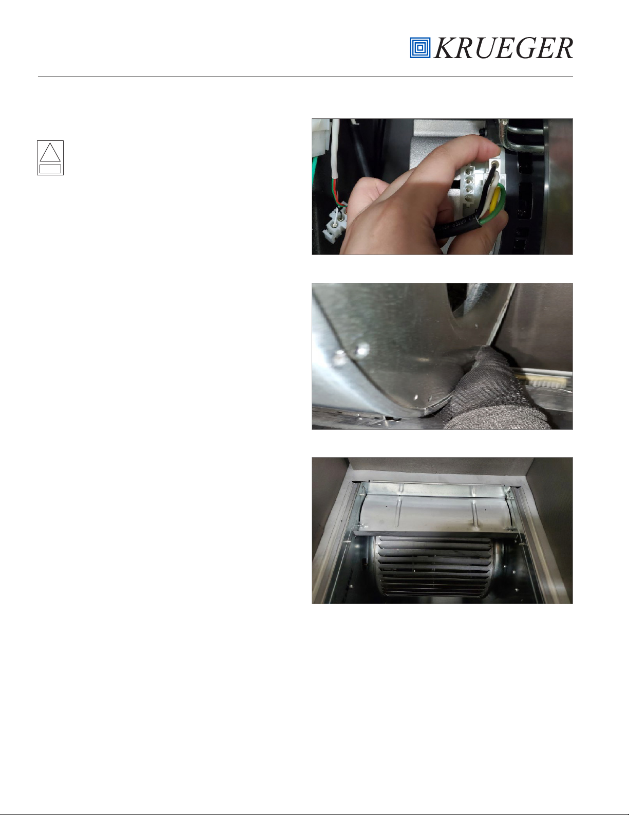
4. Remove the intake grille and wipe it down with an
appropriate surface decontaminant.
5. Place an unplugged heating device, such as a commercially
available electric frying pan with the thermostat set
at 232.2° to 246.1°C (450° to 475°F) inside the unit
through the removed prefilter access panel. Spread
the Paraformaldehyde evenly over the heating surface
of the electric frying pan. Caution: The auto-ignition
temperature of paraformaldehyde is 300°C (572°F).
Place a hot plate, beaker of water, and temperature and
humidity indicators in the unit next to the pan that will
contain the paraformaldehyde.
6. Enclose all sides of the unit with heavy gauge plastic film
and tape in place while leaving the film that will close the
space formerly occupied by the intake grille free. The
power cord should be coiled and taped to the unit and
sealed under the plastic film. Seal the film to the floor on
which the unit stands.
7. Determine the temperature and humidity inside the unit.
8. The temperature should be 21.1°C (70°F) or higher with a
humidity level between 60% to 85%. Use the hot plate to
heat the beaker of water until the desired temperature
and humidity are achieved. Disconnect the hot plate.
9. Seal the film over the remaining opening of the intake grille
space. Carefully seal around the power cord extending
from the electric frying pan so that formaldehyde gas will
not leak out.
10. Plug the cord of the electric frying pan into an outlet.
11. After the Paraformaldehyde has depolymerized,
disconnect the frying pan from the electrical outlet.
12. Allow the unit to stand for a minimum of two hours or
overnight.
13. Attach the flexible hose to the unit and allow it to draw
from inside the unit.
14. After 15 minutes of visible exhaust activity, small openings
may be made in the film over the unit’s air supply grille to
improve ventilation.
15. Allow the unit to ventilate overnight.
16. Remove the unit from exhaust ventilation when the
formaldehyde gas has been exhausted. Caution: During
unit decontamination, respiratory protection for service
personnel is highly recommended. Only national institute
for occupational safety and health (NIOSH) approved
respirators should be used.
17. Remove the HEPA filter as described previously. The filter
can now be disposed of as general waste.
Phenolic Decontamination
In facilities where Paraformaldehyde gas decontamination is
prohibited or not feasible, the unit can be disinfected by the
following procedure.
1. Remove the prefilter.
2. After the intake grille and prefilter are removed, turn
the unit on, and with the unit running, spray a mist of
phenolic disinfectant such as Amphyl or Lysol into the air
intake opening. Approximately two (2) to five (5) ounces
is adequate.
3. Remove the HEPA filter as described previously. Since the
filter has not been decontaminated by the formaldehyde
procedure, it must be placed in a red medical waste bag
and disposed of properly.

10
PAC MAX AIR CLEANER
INSTALLATION, OPERATION, AND MAINTENANCE MANUAL
If the unit requires service to repair the unit, use proper facility protocol. It is recommended to wear protective equipment,
clean the unit, and verify power has been turned off at the unit and the unit is disconnected from the power source for
initial inspection.
A few examples of issues that might occur:
INOPERATIVE AIRFLOW
1. Confirm that the power cord is plugged into the building receptacle and power is present.
2. Confirm that the unit power switch is turned “ON”.
3. Confirm the setpoint is set to a value that will allow the motor/blower to run. Recommended to change the position for
confirmation.
4. Authorized personnel can check power switch and transformer for appropriate power. Contact Krueger for more in-
depth troubleshooting, if required. Replace or repair faulty component(s).
LOW AIRFLOW
1. Check prefilter for obstruction and remove obstruction as necessary.
2. Replace dirty prefilter media.
3. Increase the setpoint requirement of the speed control.
4. Check power supply for proper voltage, amperage, and distribution frequency.
5. Check for down-stream obstructions or erratic isolation room ventilation balance.
6. Replace HEPA filter if the air velocity remains low after checking all other causes of low airflow.
HIGH AIRFLOW
1. Decrease the setpoint requirement of the speed control.
2. Verify all filters are properly in place.
SECTION FIVE - TROUBLESHOOTING

12
PAC MAX AIR CLEANER
INSTALLATION, OPERATION, AND MAINTENANCE MANUAL
PAC MAX SPECIFICATIONS
• Dimensions: 57.75” H x 26.18” W x 24.75” D, 1467 H x 665
W x 629 D (mm)
• Weight: 175 lbs. (79 kg) ship weight
• Power Requirements: 10.2 A at 120V, 60 Hz, 1-Phase,
10.3 A at 120V, 60 Hz, 1-Phase with UV Light
• Airflow: 400 CFM (679 m3/hr) at minimum ±10% and
1,700 CFM (2,888 m3/hr) at maximum ±10%
• HEPA Filter Media: 99.97% at 0.3 micron minimum
efficiency
• Prefilter: 2” MERV8 multi-pleat anti-microbial pleated
prefilter with frame
• Motor: 3/4 HP (0.56 kW), direct drive, continuous duty,
variable speed, electronically commutated motor with
sealed-for life bearings and overload protection
REPLACEMENT PARTS
SECTION SIX - MISCELLANEOUS (CONTINUED)
TABLE 1 -PAC MAX
PART NO. DESCRIPTION QUANTITY
272000-001 PAC MAX 120V 1
272000-001UV PAC MAX 120V UV 1
S272010-001 MOTOR/BLOWER ASSEMBLY, 120V 1
272022-001 99.97% HEPA FILTER 1
63352-001 ANTI-MICROBIAL PREFILTER 1
63951-002 VCU SPEED CONTROL 1
62974 CASTER WITH LOCK 2
62973 CASTER 2
63667 TRANSFORMER 120/24VAC 1
63739-002 ON/OFF SWITCH 1
272019-001 FILTER INDICATOR LIGHT 1
63415-004 PRESSURE SWITCH 1
60265-002 UV LAMP 1
272014-001 UV LIGHT ASSEMBLY 1
272025-001 POWER CORD - 120V 1
AIR CHANGE RATES
TABLE 2 - ROOM SIZE (ROOM AIR VOLUME) IN FEET
PAC
MODEL FAN SPEED 15 x 20 x 8
(2400 ft3)
20 x 20 x 8
(3200 ft3)
24 x 24 x 8
(4608 ft3)
24 x 30 x 8
(5760 ft3)
30 x 30 x 8
(7200 ft3)
30 x 40 x 8
(9600 ft3)
40 x 40 x 8
(12800 ft3)
MAX Min 400 CFM 10 ACH 7 ACH 5 ACH 4 ACH 3 ACH 2 ACH 1 ACH
MAX Max 1,700 CFM 42 ACH 31 ACH 22 ACH 17 ACH 14 ACH 10 ACH 7 ACH

13
PAC MAX AIR CLEANER
INSTALLATION, OPERATION, AND MAINTENANCE MANUAL
a) Unless otherwise set forth in the Sales Confirmation,
Seller warrants to Buyer, for a period of twelve (12) months
following the date of shipment to the Delivery Location
(the “Warranty Period”), that the Goods will be free from
defects in material and workmanship. Notwithstanding the
foregoing, the Warranty Period for consumable Goods shall
in no event exceed recommended replacement intervals
set forth in the Instructions (hereinafter defined). If, prior
to the expiration of the Warranty Period, Buyer informs
Seller in writing of any breach of this limited warranty, then
Seller may repair or replace the Goods that gave rise to such
breach or, in Seller’s sole and exclusive discretion, refund
the amounts that Buyer paid for such Goods.
The foregoing limited warranties do not apply to (i) any
defect in Goods not manufactured by Seller; and (ii) any
Goods manufactured according to Buyer’s specifications.
(b) Buyer shall bear the costs of access, de-installation, re-
installation and transportation of the Goods to Seller and
back to Buyer. Any repair or replacement pursuant to this
limited warranty shall not extend the Warranty Period.
Seller does not warrant the Goods, or any repaired or
replacement parts, against normal wear and tear. This
limited warranty and remedy are expressly conditioned
upon: (i) Buyer’s payment of the purchase price in full,
(ii) Buyer giving written notice of the defect, reasonably
described, to Seller within ten (10) days of the time when
Buyer discovers or ought to have discovered the defect,(iii)
the storage, installation, operation, use, and maintenance of
the Goods in compliance with the published specifications
and instructions provided by Seller or its suppliers or
subcontractors (the “Instructions”), (iv) the existence of
proper records of Buyer’s operation and maintenance of
the Goods during the Warranty Period, (v) Buyer providing
Seller with a reasonable opportunity to examine the Goods
and the aforementioned records, and (vi) the absence of any
unauthorized modification or repair of the Goods.
(c) Before any test may be used to evaluate the Goods, Buyer
shall: (i) provide Seller with reasonable written notification
of such test, (ii) allow Seller to be present during such test,
and (iii) receive Seller’s consent to the conditions of such test,
which consent will not be unreasonably withheld. If a test is
performed on the Goods, and Seller has not consented to
the conditions of such test, then this limited warranty shall
be void.
(d) THE REMEDIES SET FORTH IN THIS SECTION ARE
BUYER’S SOLE AND EXCLUSIVE REMEDIES FOR ANY
FAILURE OF SELLER TO COMPLY WITH ITS OBLIGATIONS
UNDER THIS AGREEMENT, INCLUDING ANY BREACH OF
THE LIMITED WARRANTY SET FORTH IN THIS SECTION.
Correcting any defect in the manner set forth in this Section
8 shall constitute complete fulfillment of Seller’s obligations
and liabilities under the Agreement following the delivery
of the Goods, regardless of whether a claim is based in
contract law, tort law (including negligence, strict liability or
otherwise), or other legal theory.
THE LIMITED WARRANTY SET FORTH IN THIS SECTION
IS EXCLUSIVE AND IN LIEU OF ALL OTHER WARRANTIES,
WHETHER STATUTORY, EXPRESS, OR IMPLIED. EXCEPT AS
SET FORTH IN THIS SECTION, SELLER MAKES NO EXPRESS
OR IMPLIED WARRANTIES, INCLUDING, BUT NOT
LIMITED TO ANY WARRANTIES OF MERCHANTABILITY,
NON-INFRINGEMENT, OR FITNESS FOR A PARTICULAR
PURPOSE, OR ANY WARRANTIES ARISING FROM COURSE
OF DEALING OR USAGE OF TRADE. Any other oral or written
statements, whether contained in general advertising or
other printed material, do not constitute warranties, and
Buyer agrees that it is not entering into the Agreement in
reliance upon any such statements.
CONTACT KRUEGER
For warranties, replacement parts, technical support, or any
other questions please contact us at the following.
tel: 972.680.9136
email: kruegerinfo@krueger-hvac.com
web: www.krueger-hvac.com
SECTION SEVEN - LIMITED WARRANTY

1401 N. Plano Rd.
Richardson, TX 75081
tel: 972.680.9136
www.krueger-hvac.com
Verasys Digital Controls: 09/2019
©Krueger 2019. All Rights Reserved.
YOUR RESOURCE FOR AIR DISTRIBUTION AND EQUIPMENT SOLUTIONS
Let us know how we can assist you in your next building application. For more information, contact
your local Krueger representative or visit us on the web at www.krueger-hvac.com.
CRITICAL ROOM SOLUTIONS
CHILLED BEAMS
DISPLACEMENT VENTILATION
UNDERFLOOR
Underoor Diusers
Underoor Terminal Units
TERMINAL UNITS
Single Duct
Fan Powered
Dual Duct
Bypass & Retrot
FAN COILS & BLOWER COILS
Horizontal
Vertical / Stack
DIFFUSERS
Plaque & Architectural
Louvered
Perforated
Modular Core
Linear Slot
Plenum Slot
Round
Air Nozzles
GRILLES & REGISTERS
Supply
Return
Linear Bar
Security
Industrial
Duct Mounted
Transfer
Stainless Steel
CONNECT WITH US!
Other manuals for PAC Series
1
Table of contents
Other KRUEGER Air Cleaner manuals