Formax Cut-True 15M User manual

Cut-True 13M
Manual Paper Cutter
OPERATOR MANUAL
FIRST EDITION
4/2015


TOPIC PAGE
Specications 1
Safety Guidelines 1
Assembly 2
Overview 3
Description of Equipment Parts 4
Operation 5-6
Maintenance 7
Replacing the Cutting Stick 7
Cutting Blade Maintenance 7
Replacing the Cutting Blade 8 - 9
TABLE OF CONTENTS

SAFETY GUIDELINES
SPECIFICATIONS
* Operators should read this manual prior to using the cutter
* The Cut-True 13M should only be used by one person at a time.
* The blade lever should be lowered using both hands.
* After making each cut, the blade lever should be moved back to the full upright and locked position.
* Do not disassemble the front Plexiglas safety cover.
* Do not grasp underneath the blade edge.
* When changing the blade, carefully follow the instructions in this manual, and be sure to use the supplied
Blade Change Safety Tool.
Cutting Action: Manual lever handle
Maximum Cutting Width: 14.567”
Maximum Paper Stack Height: .75”
Cutting Length Behind Blade 10.5”
Narrow Cut 1.25”
LED Laser Cut Line: Yes
Clamp Style: Lever
Back Gauge Adjustment: Thumbscrew
Back Gauge Reading: Scale, in both inches and metric
Blade Change Tool: Included
Dimensions: 12.75” H x 18.75” W x 17.5” L
Weight: 38 lbs.
Cut-True 13M Guillotine Cutter
1

ASSEMBLY
2
Rear Safety Cover
Rear safety
cover
Blade lever
arm
Remove the four screws indicated in g 1. Insert the rear safety cover with the notch under the clamping lever
arm (g. 2). Attach the rear safety cover by reinstalling the screws (g 3).
Blade Lever Arm
Screw the blade lever arm into the
lever arm base and hand tighten.
Batteries
Install the two “C” batteries for the laser
light into the holder on the underside of
the cutter.
Fig. 1 Fig. 2 Fig. 3
Batteries

1. Blade lever arm
2. Front safety guard
3. Blade lever locking safety arm
4. LED laser light switch
5. Blade lever safety release
6. Blade adjustment
7. Back gauge scale
8. Back gauge slide
9. Back gauge adjustment thumbscrew
10. Back gauge
11. Rear safety cover
12. Blade housing cover
13. Clamping lever
14. Blade carrier
15. Cutting stick
16. Cutting blade
17. Blade change safety tools
18. “T” handle Allen wrench
1
OVERVIEW
2
13
11
10
9
8
7
6
5
4
3
12
14
15
16
17
3
18

DESCRIPTION OF EQUIPMENT PARTS
1. Blade Lever Arm Lever-action provides robust cutting with minimal effort. After each cut, the
lever must be returned to its full upright and locked position.
2. Front Safety Guard Prevents operators from placing hands or other objects in the cutting area.
Must be in the lowered/closed position in order to operate the cutter. The
guard can only be reopened when the knife lever is in the upright, locked
position.
3. Blade lever locking safety arm Locks the blade lever arm safety release in position when the front safety
guard is open.
4. LED laser light switch Turns the laser light beam on and off.
5. Blade lever safety release Locks the blade in the open position. Slide the safety lever to the left to
lower the blade lever arm.
6. Blade adjustment access The blade height can be adjusted up to 2mm by using the adjustment screw.
To lower the blade (+), turn to the left. To raise the blade (-), turn to the right.
NOTE: If the blade is adjusted too low, it will cut deeply into the cutting stick,
damaging not only the stick but the cutting blade. The optimal blade height
is when the bottom sheet in a stack is cut accurately.
7. Back gauge scale In mm/cm and inches.
8. Back gauge slide Guides the back gauge forward and back.
9. Back gauge adjustment thumb-
screw
Loosen the thumbscrew to move the back gauge forward and backward.
10. Back gauge Moved by loosening the back gauge thumbscrew. Used to move the paper
stack to the appropriate cutting position and to safely remove paper from the
cutter.
11. Rear safety cover Clear acrylic cover is provided for operator safety and helps to prevent dust
buildup.
12. Blade housing cover Attached to the machine with 5 screws. Only disassemble in case of blade
change or maintenance. Before removing the cover, the blade lever arm
must be removed.
13. Clamping lever Lowers the clamping device that holds the paper stack rmly in position.
14. Blade carrier Holds the blade during operation. Blade is attached with 4 screws.
15. Cutting stick Plastic stick which protects the edge of the blade during cutting. Can be
rotated and repositioned to be used up to 8 times before being replaced.
16. Cutting blade Heat-treated high-carbon steel blade.
17. Blade change safety tools Used to safely remove the blade when it needs to be re-sharpened or re-
placed.
18. “T” handle Allen wrench Used to adjust blade and remove cutting stick
4

1. Turn on the LED Laser Light.
2. Raise the blade lever arm to the upright, locked posi-
tion.
3. Loosen the back gauge thumbscrew and slide the
back gauge forward or back to set it for the correct
paper length then re-tighten the thumbscrew. The
back gauge scale is marked for both standard and
metric measurements.
4. Raise the front safety cover. Slide the paper stack
into the cutter along the left edge, using the align-
ment bar for guidance. Push it as far back as pos-
sible toward the back gauge, without placing hands
under the cutting blade.
Important Note: When cutting pieces less than
2” insert the longer side of the document for safe
removal after cut.
5. Lower the front safety cover.
6. Move the clamping lever to the left to lower the
clamp and secure the paper in place.
OPERATION
5

7. Grasp the blade lever arm and lower it slightly while
at the same time sliding the safety lever to the right
(inset) to engage the blade lever arm.
8. Use both hands to grasp the blade lever arm and
bring it down to cut through the paper stack. When
the cut is complete, raise the lever arm to its top
position until it locks into place.
9. Move the clamping lever to the right to raise the
clamp and release the paper.
10. Lift the front safety cover.
11. Loosen the back gauge thumbscrew and slide the
back gauge forward to safely remove the paper.
Important Note: When cutting pieces less than
2” insert the longer side of the document for safe
removal after cut.
6

MAINTENANCE
REPLACING THE CUTTING STICK
All moving parts with screws should be checked periodically to be sure the screws are tight. They may become loose in
the process of transportation. Users should also check and tighten the screws after more than 200 cutting cycles.
All moving parts should be lubricated and oiled periodically to maintain performance and equipment life. Before lubricat-
ing, these parts should be cleaned to remove paper dust and old deposits of oil and grease.
The cutting stick is the surface the blade contacts during the
cutting process. It can be turned or rotated and used twice
on each side, 8 times altogether.
If the last piece of paper in the stack is not cut through
cleanly, and the blade height has been adjusted properly, the
cutting stick should be turned, rotated or replaced.
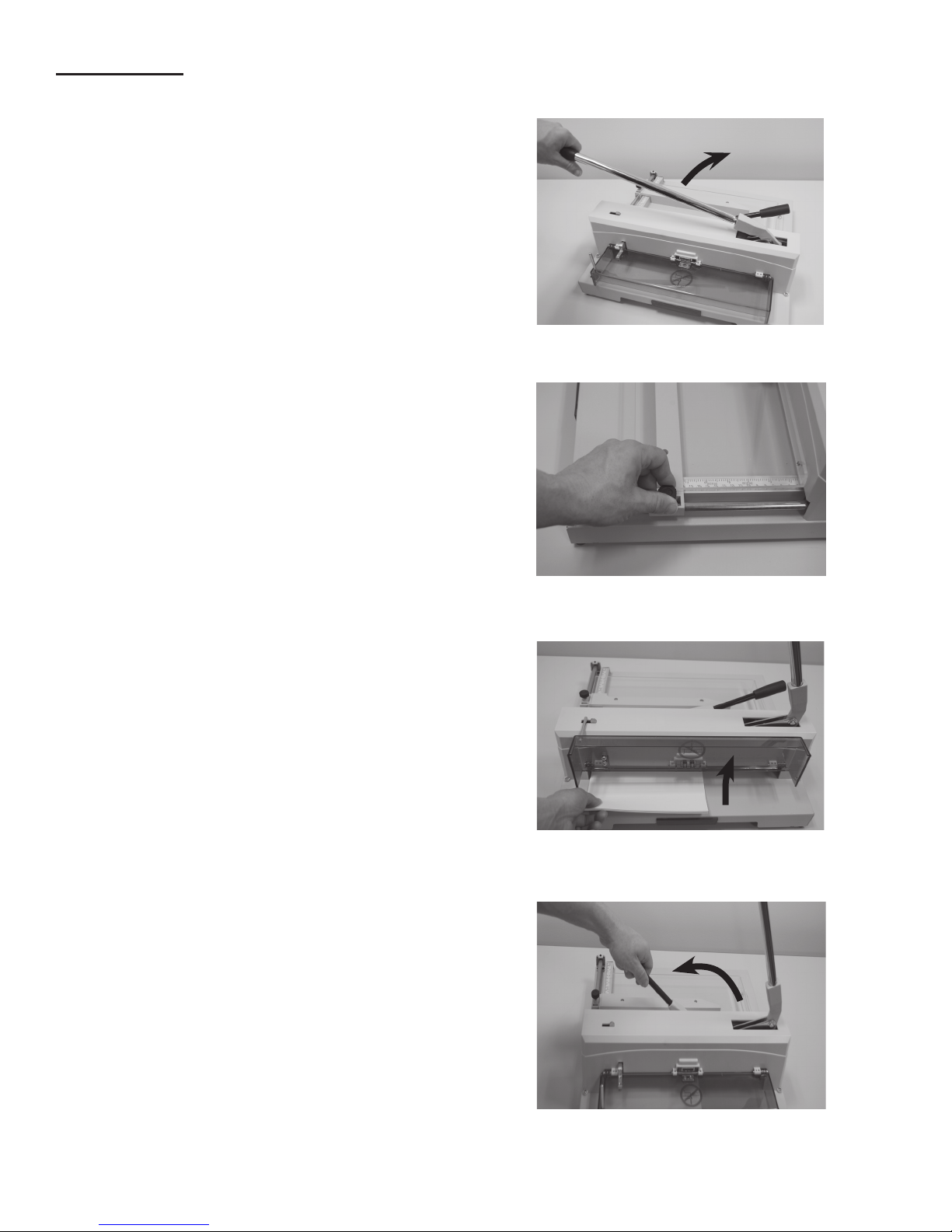
The cutting stick sits in a channel in the base of the cutter. To
remove the stick, insert the “T” red-handled Allen wrench tool
into the hole in the end of the cutting stick through the open-
ing on the left side of the blade housing cover and lift the
stick up and out. Turn the stick 180 degrees to use the same
cutting side, or rotate to a new side if the rst has already
been used twice.
NOTE: When the cutting stick is rotated or replaced, the
blade height must be readjusted. A blade which cuts too
deeply damages not only the cutting stick but the blade itself.
The optimal blade height is when the last sheet in a stack is
cut accurately. The blade height can be adjusted up to 2mm
by using the adjustment screw located on the left side of the
cutting head. To lower the blade (+), turn to the left. To raise
the blade (-), turn to the right.
CUTTING BLADE MAINTENANCE
The cutting blade is made of heat-treated high-carbon steel and is designed for repeated use. However, over time the
blade will become dull, and not perform to the highest standards. Cutting heavy paper or cardboard will dull the blade
more quickly than thinner paper stock. A dull blade will not cut accurately. If the blade jams in the paper stack or leaves a
groove in the paper, it should be changed immediately.
If the blade is not making clean, accurate cuts, check the following:
* Have you rotated or replaced the cutting stick?
* Have you correctly adjusted the height of the blade?
If so, the blade will need to be replaced. The blade can either be re-sharpened by a professional, or it can be replaced
with a new blade. To avoid injury, follow the Blade Changing Procedure and use the Blade Change Safety Tool, included
with the cutter.
7
Cutting stick

REPLACING THE CUTTING BLADE
1. Remove the blade lever arm and the blade housing
cover. Then reinstall the blade lever arm.
4. Remove the two outer screws.
5. Raise the blade lever arm.
6. Slowly turn the handles of the safety tool slightly to
the left, just enough to release the blade from the
machine. Then carefully remove the blade.
2. Lower the blade lever arm.
3. Remove the two middle blade screws and install the
blade carrier tools.
8

9
7. Carefully remove the old blade from the blade
change tools. Set the blade on a at surface and
unscrew the handles. Cap the old blade with a
protective pad to prevent injury.
8. Place the new blade with the beveled cutting edge
facing up, and the screw holes at the top, as shown
here. Remove the protective pad from the new
blade.
Attach the blade change tools to the new blade.
Do not screw the blade tools all the way in, there
needs to be enough of a gap approx. 1/4” so the
blade can be slid back into position.Then reverse
the procedure to install the new blade.
9. After installing the new blade, it will need to be
adjusted for proper positioning and cutting depth.
10. Carefully move the blade to the cutting stick by low-
ering the blade lever arm. NOTE: Keep hands and
objects out of the path of the blade.
11. Turn the blade adjustment screw (X) to the right
(-) until you have a visible ray of light between the
blade and the cutting stick.
12. Adjust the blade to touch the cutting stick evenly by
using the two screws at the top (Y).
13. Raise the blade lever arm to the top position and
lock it. Then make a trial cut with a single sheet of
paper. If the paper is not cut through completely, the
blade must be adjusted using the screws (X)
and/or (Y).
NOTE: The two (Y) screws are for horizontal
adjustment and the (X) screw is for minor up-down
adjustment.
14. Reassemble the blade housing cover, the front
safety cover, and reattach the the blade arm lever.
Y
X
Cutting edge
Other manuals for Cut-True 15M
1
Table of contents
Other Formax Paper Cutter manuals
Popular Paper Cutter manuals by other brands

MyBinding
MyBinding MBM Kutrimmer Series instruction manual

GBC
GBC ProCut 20P Installation and operation manual

UBI
UBI EasyCoder 401 installation instructions

Challenge
Challenge TITAN 200BC Operator's manual

Krug & Priester
Krug & Priester IDEAL 4810-95 operating instructions

Challenge
Challenge Champion 305 XD Operator's manual

Duplo
Duplo DC-616 Service manual

Quality Commercial Macines
Quality Commercial Macines QCM-1200E user manual

ABC Office
ABC Office Ideal Cutter 4810 user manual

Intimus
Intimus 4340 M Original instructions

Challenge
Challenge SPARTAN 185A Operator's manual

Challenge
Challenge CHAMPION 305 TC Instructions and parts manual