KS RnD KS200-4G User manual

KS200-4G
Automotive Gas Analyzer
Manual
(Ver. 0.1.4)

Contents
1. Safety guideline ……………………………………………………………………………… 3
1-1 Purpose of use …………………………………………………………………………… 3
1- Terms of use …………………………………………………………………………… 3
2. Product descriptions ………………………………………………………………………… 4
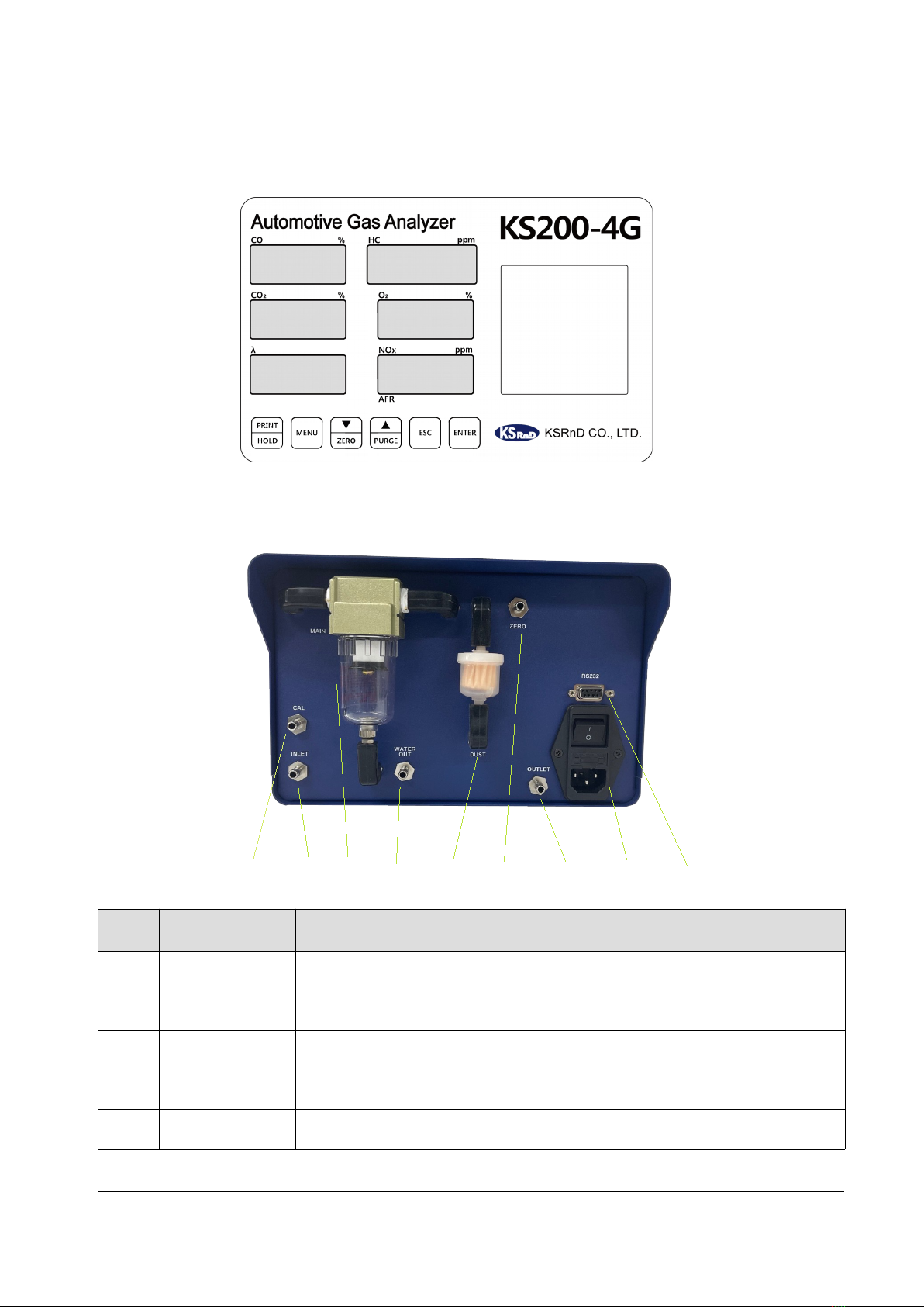
-1 Outlook …………………………………………………………………………………… 4
- Front Part …………………………………………………………………………………… 5
-3 Back Part …………………………………………………………………………………… 5
-4 Specification …………………………………………………………………………………… 6
3. Installation and precautions ……………………………………………………………… 7
3-1 How to install …………………………………………………………………………………… 7
4. Measure ent Mode…………………………………………………………………………… 8
4-1 Warm up ………………………………………………………………………………………… 8
4- Ready ……………………………………………………………………………………………… 9
4-3 Purge……………………………………………………………………………………………… 10
4-4 Measurement ………………………………………………………………………………… 10
4-5 Leak test …………………………………………………………………………………… 10
4-6 Print ………………………………………………………………………………………… 11
5. Select Mode ………………………………………………………………………………… 1
5-1 Key & Function ………………………………………………………………………………… 1
5- HC test ………………………………………………………………………………………… 13
5-3 Choice Fuel ……………………………………………………………………………………… 14
5-4 HCV , OCV , Ramda calculation …………………………………………………………… 14
5-5 PEF ………………………………………………………………………………………… 15
5-6 Set Date ………………………………………………………………………………………… 16
5-7 Calibrate gas……………………………………………………………………………………… 16
6. Others ………………………………………………………………………………………… 3
6-1 Flow diagram …………………………………………………………………………………… 3
6- Electric block diagram ………………………………………………………………………… 3
6-3 Dust filter………………………………………………………………………………………… 4
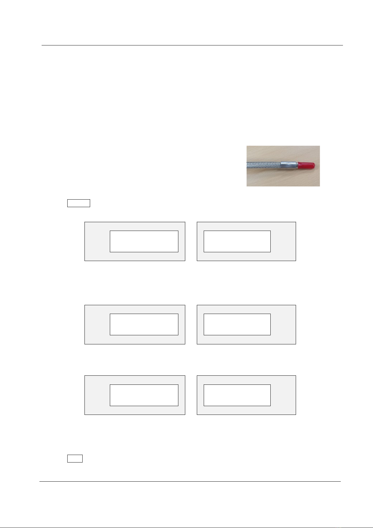
6-4 Probe …………………………………………………………………………………………… 5
6-5 Accessories………………………………………………………………………………………… 6

1. Safety guideline
1-1. Purpose to use
KS 00-4G measures the concentration of automobile exhaust gas to diagnose and maintain the
condition of the vehicle. .
1- . Terms of use
① Use the rated voltage.
② An altitude of less than 1000m and a humidity of less than 85%.
③ Install in a place where there is no direct sunlight, vibration, or sudden temperature change.
④ Install it in a well-ventilated place.
⑤ Install at least 5cm above the ground.
*Notice
If anything unusual occurs, please stop using it immediately and contact the place
of purchase or headquarters for inspection.
Waring
① Please check power before using.
② When probe in and out watch out for burns..
③ Don’t stay longer when the exhaust gas is generated.
* As the exhaust gas contains carbon onoxide (CO) and nitrogen oxide (NOx) that cause fatal
da age to the hu an body, use it in a ventilable place at all ti es.

KS200-4G MANUAL
2. Specification
-1. Product
① Full ② Front
③ Side ④ Back
4/26

KS200-4G MANUAL
- . Display
-3. Back
⑨ ④ ⑦ ⑧ ③ ⑥ ⑤ ① ②
NO. NAME Description
① Power switch 0V (1A Fuse in it)
② RS 3 9Pin connector(communication)
③ Dust filter Remove dust
④ INLET Gas inlet or Cal gas inlet (Using pump)
⑤ OUTLET Gas outlet
5/26

KS200-4G MANUAL
⑥ ZERO INLET Set ZERO for air inlet
⑦ Main filter Water separation & remove dust
⑧ WATER OUTLET Water out
⑨ CAL Cal gas inlet (NOT using pump)
-4. KS 00-4G Specification (Blue is Option)
Measure ent ite s CO, HC, CO ,O ,NOx, Ramda, AFR
Measure ent principle
CO,HC,CO : Non-Dispersive Infrared
O ,NOx : Electro-Chemical
Measuring range
/
Resolution function
CO 9.99% HC 9999 ppm CO 0.0%
0.01% 1 ppm 0.01%
O 5.00% Ram
da
,000 AFR 99.0
0.01% 0.001 0.1
NOx 0~5,000ppm
1ppm
Repeatability Under % FS
Response ti e 10 sec (over 90%)
Preheating ti e 8~10 min
Sa pling volu e 4L/min
Power 100~ 0V Free Voltage
Power Consu ption 50W
Te perature -10℃ ~ 40℃
Size 45(W) x 380(D) x 155(H)mm
Weight 6kg
Output Method RS 3 , 4times /sec
Printer Built-in thermal printer (option)
Display 4 digit 7 segment LED
6/26

KS200-4G MANUAL
3. Installation and precautions
3-1. Installation
① Insert one end of the probe hose into the measurement probe and the other end into the analyzer
GAS INLET.
*The exhaust of a car can pulse, especially at low RPM, drawing air in causing bad readings ensure the
flexible probe is fully inserted.
② Place the power switch off, connect the one-touch fitting to the analyzer Inlet and Outlet, and
then connect the probe to the fitting on the Inlet side. After that, connect the power cable to the
power socket behind the analyzer.
*Notice
Please check the probe and filters connection status
7/26

KS200-4G MANUAL
4. Measure ent Mode
4-1. Warm up
① Power [ON] and start initialization.
VEr
0.63
ppm
WarM
UP
ppm
tIME
351
ppm
② Warming up is carried out step by step, and the initial count value may vary depending on the
surrounding temperature or the state of use of the device.
*The count value is reduced in the ready state for device preheating.
※ Please place the probe end in a clean at osphere.
③ End of warm up, set ZERO automatically.
ZEro
20
ppm
④ When analyzer ready, the following message will be displayed.
rdy
odE
ppm
8/26

KS200-4G MANUAL
4- . Ready Mode
① Ready Mode: It refers to a state in which the
power is [ON] but the suction pump is [OFF]
when the measurement is not performed for
a long time.
* KS 00-4G automatically turns off the pump
after 30 minutes to maintain the standby
state.
② After 10 minutes from the ready state, it
automatically changes to STAND-BY mode.
③ Press any button in STAND-BY mode to return to standby again with zero. (STAND-BY mode is not
displayed.)
4-3. PURGE
Purge is to clean the remaining gas in the cells and probes inside the equipment with clear air.
PressPURGEkey clean up probe 1 0sec and set ZERO automatically.
Purg
120
ppm
ZEro
20
ppm
★ Please place the probe end in a clean air.(For refresh.)
9/26
PURGE Key Clean pro e
(120 sec)
Auto zero
set

KS200-4G MANUAL
4-4. Measurement
① Probe put on clean air press ZERO key start cal.
② Insert the probe of the measuring instrument and press ENTER key measure the exhaust gas.
③ After measuring it, remove the probe from the exhaust port. press PURGE key Clean inside with
fresh air for value reduce to “o”.
④ When the measured value is "0" press ESC key stay on ready mode.
4-5. Leak test
To ensure the gas sampling system is sealed correctly and
not letting in air, the analyzer will perform a leak check.
This requires the user to block the probe inlet and perform the test.
① End of the probe put the cap on.
② Press MENU key choose mode.
LEAK
TEST
ppm
③ When pump on, can check the pressure indication value falls.
Make sure the dropped pressure value is maintained.
LEAK
43.5
ppm
④ Display the status as Pass and Fail.
LEAK
PASS
ppm
** If the result is Fail, please check probe hose and leak cap and test again.
⑤ Press ESC key return to ready mode.
10/26

KS200-4G MANUAL
4-6. Printer
① When the result value comes out, press the key to print it.
② Print mark.
KS200-4G
Automotive Emission Analyzer
2021/1/1 AM 09:00:00
CO 0.00%
HC 0000ppm
CO₂ 00.0%
O₂ 20.9%
Nox 0000ppm
λ 1.000
AFR 00.0
KSRnD CO., LTD.
5. Select Mode
5-1. KEY and FUNCTION
11/26

KS200-4G MANUAL
NO. NAME FUNCTION
①SELECT Use it when choosing a menu or additional function.
②PRINT print
③UP/ PURGE Purge or Increase Value
④DOWN/ZERO Move position
⑤ ESC Use when ending the selection mode and switching to the
measurement mode.
⑥ ENTER Enter measurement mode and Save the data
*Each time you press MENU key, the mode changes in the order below.
NO. NAME FUNCTION
①READY MODE Ready mode
②LEAK TEST Leak test
③HC TEST Check HC remaining gas
④FUEL Choose Fuel
⑤HCV/OCV HCV / OCV
⑥PEF PEF
⑦DATE SETTING Set date and time
⑧CAL CAL GAS mode
⑨VERSION Display version
⑩NOx Check NOx sensor
*Press MENU can using ▼ , ▲ , SET, ESC , SELECT
12/26

KS200-4G MANUAL
5- . HC Test
During vehicle exhaust gas measurement, the level of contamination is indicated by measuring the
sample collection probe line and the hydrocarbon (HC) component accumulated inside the analyzer.
① In ready mode press MENU key move on “ HC TEST ”.
② Press ENTER key, start ZERO function.
③ ZERO is complete, start HC % vol test.
CO %
HC ppm
HC tESt
λ
NOx ppm
tIME 30
CO %
HC ppm
HC 17
λ
NOx ppm
PASS
④ If HC % vol reading does not go below 0 ppm when in fresh air following a test then a
residue check will be requested. Repeat tests will be carried out until the reading is below 0 ppm.
<If Fail>
Sampling gas Since the inside of the probe or device is contaminated, have to change the dust
filter.
Press the [PURGE] key to clean it with clean air and re-measure HC to check.
13/26

KS200-4G MANUAL
5-3. Choice FUEL
choose the fuel for the measurement vehicle, calculrate RAMDA and AFR.
① In ready mode press MENU key move on “FUEL ****” .
②press ▼ , ▲ choose fuel press ENTER key.
Fuel start GASOLIN → LPG → CNG → ALCOHOL and the end.
5-4. HCV and OCV
Display fuel HCV and OCV.
① In ready mode press MENU key can check. ( ex- HCV : 1.8500, OCV : 0.0000 )
CO %
HC ppm
Hcv 1. 8500
λ
NOx ppm
Ocv 0. 0000
14/26

KS200-4G MANUAL
* For Lambda calculation, based upon measurements of CO, CO , HC and O , the following formula
is standardized: Displayed on the instrument as LAMBDA (O).
Gasoline LPG CNG Alcohol
HCV 1.8500 .5000 3.8300 3.0000
OCV 0.0000 0.0000 0.0000 0.5000
AFR 14.7 15.5 16.9 9.0
* LAMBDA CALCULATIONS - Brettschneider
5-5. PEF
PEF(Propane Equivalency Factor) Propane equivalence factor or n-hexane to propane ratio
as set in the instrument. This is not a user variable parameter but is displayed for reference.
15/26

KS200-4G MANUAL
① In ready mode press MENU can check it.
CO %
HC ppm
PEF 0.500
λ
NOx ppm
5-6. Set date
Can set date and time.
① Press the MENU key in standby mode to move to the time setting. Now you can see the current
time.
CO %
HC ppm
dAtE
2021 05.05
λ
NOx ppm
AM 10.30
① Press the ENTER key, the year digit blinks, and the setting mode is ready.
②Press ▼ , ▲ to set the desired time, and press ENTER to display "SAVE" then save. You can set
time in the order of year → month → day → morning/afternoon → hour → minutes.
16/26

KS200-4G MANUAL
*Notice
Check the gas pressure meets the prescribed value.
5-7- . Calibration gas setting
1) material
항목 내용
Standard gas Standard gas with a test report from an accredited institution.
Suggest gas CO : 1.00~6.00%m C3H8 : 500~ 000ppm, CO : 1 ~15%
N balance
Supply rate 4~6L/min
Pressure regulator Use pressure and flow meter that displays primary and secondary
pressure gauges and a product with a flow control valve.
)Connecting method
- Standard gas cylinder preparation
order.
① The primary and secondary valves of the standard gas cylinder must be turned clockwise (closed)
and left the cut-off state.
② Release the gas injection pressure control valve counterclockwise to place the pressure-free and
open the primary valve of the standard gas cylinder counterclockwise. At this time, the remaining
gas in the tank is displayed on the primary gauge.
③ Turn the gas injection pressure control valve clockwise to adjust the secondary gauge pressure to
3kgf/cm².
④ Connect the drain hose to the outlet and water outlet nipple.
❖ The standard gas contains toxic ingredients. To prevent direct inhale make sure to prepare for
emissions in the exhaust analyzer outlet and calibrate in a well-ventilated place.
17/26

KS200-4G MANUAL
5-7-3. Calibration
① Place the analyzer in [standby].
CO %
HC ppm
rdy odE
λ
NOx ppm
② Press the MENU key until the screen below appears.
CO %
HC ppm
CAL gAs
λ
NOx ppm
③ Press the ENTER key, it will be automatically [zero adjustments].
CO %
HC ppm
CAL gAs
λ
NOx ppm
ZEro 20
18/26

KS200-4G MANUAL
④ After [ZERO Adjustment], it displays the previously set gas concentration value, and the top spot
blinks.
CO %
HC ppm
1.20
501
11.1 1.05
λ
NOx ppm
⑥ Pressing the ▲ key increases the value of the blinking number and sets the number. Pressing
the ▼ key moves the blinking value to the next. Repeat the procedure to set the gas concentration,
then press the ENTER key to save the concentration value and move to the next operation.
⑦ This screen displays the current gas concentration.
CO %
HC ppm
0.00
0
0.0 0.00
λ
NOx ppm
19/26

KS200-4G MANUAL
⑧ [CAL] Connect the tube of the standard gas cylinder to the inlet and turn the cylinder secondary
valve of the standard gas counterclockwise to adjust the flow meter scale to 4 to 6 L/min.
CO %
HC ppm
1.22
490
10.1 1.25
λ
NOx ppm
⑨ When the gas concentration value rises and the value stabilizes, press the MENU key and the
ENTER key simultaneously to perform gas calibration.
CO %
HC ppm
PASS
PASS
PASS PASS
λ
NOx ppm
⑩ If it is completed successfully, the display displays [PASS] as above. Press the ENTER key to check
the corrected concentration value. Turn the cylinder secondary valve of the standard gas clockwise to
lock the gas, disconnect the hose connected to the INLET, and press the ENTER key.
⑪ Run [PURGE CELL] for 1 0 seconds, perform [ZERO Adjustment], end the calibration mode, and
move to [Standby Mode].
⑫ If the gas calibration fails, [FAIL] is displayed in the corresponding display window.
*If [FAIL] is displayed, move to standby mode, press the PURGE key to clean the sample cell
for 2 to 3 minutes ith clean air, and perform gas calibration again.
20/26
Table of contents
Other KS RnD Measuring Instrument manuals