Axis ME-03 User manual

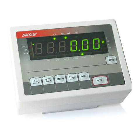
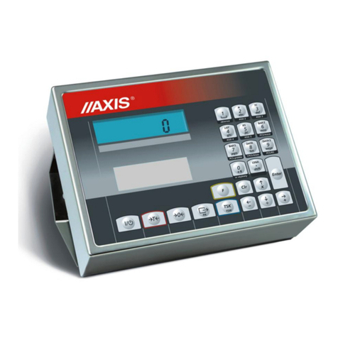
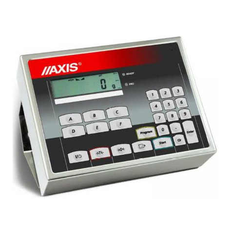
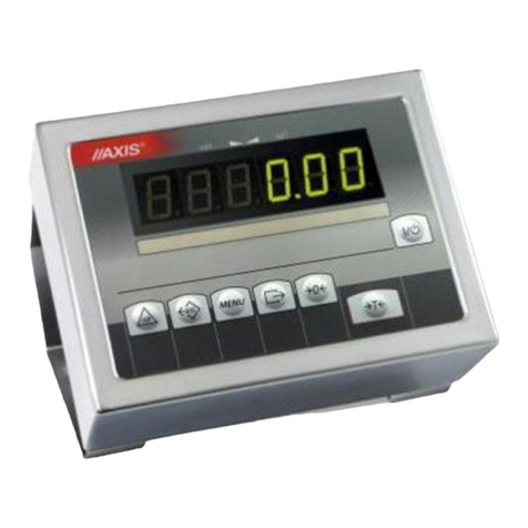
ME-03 meter
User manual
File: 2018-01-29-DTR-ME-03 ML0018 GB
AXIS, 80-125 Gdańsk, ul.Kartuska 375B, www.axis.pl

2USER MANUAL
Content:
1. General information........................................................................................................................................................... 3
2. Set..................................................................................................................................................................................... 3
3. Technical data................................................................................................................................................................... 4
4. General view and meter’s mounting method..................................................................................................................... 5
5. Keys and indicators........................................................................................................................................................... 7
6. Security rules .................................................................................................................................................................... 8
7. Rules proceeding with used up scales.............................................................................................................................. 9
8. Assembly and connecting tensometric sensors .............................................................................................................. 10
9. Meter connections description ........................................................................................................................................ 12
9.1 Threshold interface ......................................................................................................................................................... 12
9.2 External keys................................................................................................................................................................... 13
9.3 Data transmission LonG protocol.................................................................................................................................... 15
9.4 Data transmission EPL protocol..................................................................................................................................... 17
10. Exploitation general rules................................................................................................................................................ 18
11. Balance checking and adjustment .................................................................................................................................. 19
12. Start-up ........................................................................................................................................................................... 20
13. Weighing with tare........................................................................................................................................................... 21
14. Scale menu - diagram ..................................................................................................................................................... 21
15. Menu navigation rules ..................................................................................................................................................... 26
16. Labels.............................................................................................................................................................................. 26
16.1 General rules................................................................................................................................................................ 26
16.2 Labels database........................................................................................................................................................... 27
16.3 Users base ................................................................................................................................................................... 32
16.4 Fields to printout (SCALE mode) ................................................................................................................................. 33
16.5 Fields order (SCALE mode) ......................................................................................................................................... 34
17. Configuration................................................................................................................................................................... 35
17.1 Auto-zeroing................................................................................................................................................................. 35
17.2 Unit selection................................................................................................................................................................ 35
17.3 Setting serial port parameters (Interface)..................................................................................................................... 36
17.4 Language selection (Language)................................................................................................................................... 37
17.5 Setting date and time ................................................................................................................................................... 37
17.6 Keyboard...................................................................................................................................................................... 37
18. Troubleshooting and maintenance.................................................................................................................................. 38
Annex A 39
Annex B 42

3USER MANUAL ME-03
1. General information
ME-03/N/GLCD meter replaces standard meters produced by AXIS in order to extend functionality by
cooperation with ZEBRA label printers (with EPL-2 and ZPL-2 protocol).
Meter is equipped with hermetic housing made from stainless steel and graphical display.
Meter can be a part of industrial platform scale produced by AXIS.
2. Set
Basic set consists:
1. Meter
2. TN/20/10/7-3C90 core –1 pc (if only weighing meter is ordered)
3. WE-05 cable
4. MM adapter

4USER MANUAL
3. Technical data
Parameter
ME-03/N/GLCD
Designation
to III class scales
one and two-ranged
with verification units number n 6000
Max verification units number
6000
Internal resolution
1:16 777 216
Power supply
AC: 230V 50Hz DC: 12V or accumulator 6V ÷ 12 V
Keyboard
Function keys, alphanumeric keys
Display
Graphical
Transducer supply voltage
DC: 5V or 5V keying(choper)
Voltage measurement range
-10 mV ÷ 10 mV or 0 mV ÷ 10 mV
Maximal voltage signal for stable loading
+ 10 mV
Minimal voltage signal for stable loading
- 10 mV or 0 mV
Minimal allowable input signal corresponding
to verification unit e
0,3 μV
Sensor impedance range
40÷4000
Work temperature range
- 10 C ÷ +40 C
Part of limiting error
0,5
Sensor connecting
4 or 6 conductor system
Maximal cable length
75 m/mm2
Primary measurement module functions
- gross and net weight indication
- automatic and semi-automatic zeroing
- semi-automatic tare,
- connection with label printer (RS232C)
Enclosure type
ODN
Security level
IP65
Dimensions
270x180x86mm
Weight
3kg
The metrological parameters of the balance are indicated on the rating plate.

5USER MANUAL ME-03
4. General view and meter’s mounting method
Basic version (on cable):
On column mounting version:
Space for ~230V wire
Space for sensor wire

6USER MANUAL
Assembly
ME-03/N/GLCD
Meter grip assembly
3 ways to mount the meter
to wall
Mounting to wall or desktop
2 holes Ф5/10, spacing 256mm

7USER MANUAL ME-03
5. Keys and indicators
key
I/
-switch-on / switch-off (standby),
"
T
-tare,
"
0
-zeroing,
"
-label printout,
"
MENU
-menu,
"
F1
-label number selection; hold longer –temporary selection of other
product for the actual label,
"
F2
-cumulative label printout level I (if it is set)
"
F3
-cumulative label printout level II (if it is set)
"
F4
-inscribing code 1 (operator)
"
F5
-inscribing code 2 (contractor/buyer)
"
F6
-inscribing code 3 (lot/batch)
"
F7
-inscribing code 4
"
F8
-turn on/off inscribed tare value
"
F9
-switching indication between weighing –pieces counting (PCS); hold
longer –entering pieces counting function
"
F10
-switching indication between weighing –total weight (TOTAL)
"
START ()
-menu navigation,
"
STOP ()
-menu navigation (enter)
"
RESTART ()
-menu navigation (back to previous level),
"
PAUSE ()
-menu navigation,
indicator
0
-zero indication (scale not loaded),
"
-weighing result stabilization,
"
NET
-net weight (after using T),
"
MODE
-special function menu turning on indicator
"
B/G
-gross weight (after using TARE i klawisza
)
"
g, kg, ct, lb,mg
-indication unit,

8USER MANUAL
"
pcs
-pcs indication,
"
OFF
-scale turned off by key (standby)
"
MIN
-weighing result below threshold I (thr function),
"
OK
-weighing result between I and II threshold,
"
MAX
-weighing result above II threshold,
line
Indicator
-load indicator (0-100%)
Additional
indicators
(visible after activation of proper print field):
NR :
-label number
P_ID :
-product ID
NA_P :
-product name
U_ID :
-User ID
NA_U :
-User name
P_NR:
-Product no
6. Security rules
To avoid electrical shock, scale or other connected peripheral devices
damage, it is necessary to follow the security rules below.
To supply the scale use power outlet with protective contact (not for scales with external
feeder).
Repairs and essential scale regulations can be made only by authorized personnel.
To avoid fire risk use a feeder of an appropriate type (supplied with a scale). Pay attention
that supply voltage is compatible with specified technical data.
Do not use a scale when its cover is opened.
Do not use a scale in explosive conditions.
Do not use a scale in high humidity.
If a scale seems not to operate properly, plug it out of the mains and do not use it until
checked by authorized service.

9USER MANUAL ME-03
7. Rules proceeding with used up scales
According to obligatory rules concerning environment protection used
electronic devices should not be put in a container with normal waste.
•After exploitation used scale should be given to special units authorized to collect used
electronic equipment or to the place where the device was bought.

10 USER MANUAL
8. Assembly and connecting tensometric sensors
To build a scale basing on ME-03 indicator contact authorized manufacturer.
To comply CE marking requirements, for connecting the wires use filtering core 20mm.
The core should be placed within 30mm from the place of its connection.
Single strain gauge scheme inside ME-03:
When 6-wires connection of strain gauge transducers is used (REF+ and REF) jumpers shown on the picture
above should be soldered out from the main board (jumpres connect REF+ with EXC+ and REF- with EXC-
).
Before connecting sensors to the indicator unplug the device from the mains
to avoid damaging the indicator.
REF-EXC
sensor safety
wire - 2 conduits
mains safety wire
screening
Sensor signal - 4 conduits
- 2 conduits

11 USER MANUAL ME-03
Diagram of common wires and shields in the platform balances:
Z
W
Caution:
The galvanic connection of sensors and adder housing is necessary.
In normal conditions grounding is made only by using W conductor.
In conditions of increased electrostatics grounding should be made with additional Z conductor (minimum
2,5 mm2).
Connect conductors from external devices to meter sockets, led out wires or to bar on supply board inside
the meter (option). During leading out wires from meter housing use hermetic culverts in housing.
All devices connected to the scale should be supplied from the same phase
230V.

12 USER MANUAL
9. Meter connections description
ME-03/N/GLCD:
9.1 Threshold interface
P1-P3 (THRESHOLDS) outputs are used to connect dosing or signalling (option) devices. There are opto-
isolators of an open collector type with 50mA / 24V maximum load. They can be connected directly to
transmitters inputs or to MS3K/P board offered by AXIS separately or in ST 3K/P control box (3 transmitters,
own power supply)..
Optional indicators outer wires have digital markers.
Marker No.
Signal
Wire color*
1
P1 (I threshold)
Green
2
P2 (II threshold)
White
3
P3 (zero)
brown
10
GND (indicator ground)
black or yellow
*colors might change
Seal wires for
interfaces
~230V

13 USER MANUAL ME-03
Direct connection of transmitter to THRESHOLD output diagram:
* in option without an interface –10 is in the place of 8
Outputs are adapted for direct connection RM96P transmitter of DC24V input voltage and AC250V 8A
output. Transmitter’s coil has to be secured with diode e.g. 1N4148.
It is recommended to use MS 3K/P electronic board (3 transmitters of RM96P type –max. load of 3A/250V)
or complete ST 3K/P control box (feeder, 3 transmitters like above).
9.2 External keys
The input of external keys allows to place (make double) selected scale keys into control box or operator’s
workstation. As a standard the input is taken out with a wire for direct connect to a control panel. ME-03
meters can be eqipped with external keys (option od demand).
Marker numbers and outer wires colors indicators:
Nr
External keys input
Wire color
12
Yellow
13
MENU
Brown
15
0
Green
18
T
White
20
+24V (external supplier)
Pink
21
I/
Blue
22
HR
Red
23
B/G
Purple
* colors might change
External key connecting is shown below. It is crucial to use external supply (24V) in order to make current
flow through scale transoptor input. This way of connection provides galvanic separation of the scale from
automatics systems which increases resistance to external interference and increases reliability.

14 USER MANUAL
External keys connecting:
Standard Option with interface
Scale External keys Scale External keys
+24V
B/G
MENU
12
13
23
20
transoptor
+24V
DC
T
MENU
0
HR
B/G
1
6
2
7
3
8
4
9
5

15 USER MANUAL ME-03
9.3 Data transmission LonG protocol
Long protocol is used for communication with computer or standard receipt printer (AXIS C-001, Picco M,
MEFKA-1 PDT).
Transmission parameters: 8 bits, 1 stop bit, no parity, baud rate 9600bps,
RS232C interface description
Data exchange (communication):
Readout of scale indication
ComputerScale: SI CR LF (53h 49h 0Dh 0Ah),
ScaleComputer: scale response according to description below (16 bytes):
Byte
1
-
sign „-” or space
Byte
2
-
space
Byte
34
-
digit or space
Byte
5÷9
-
digit, decimal point or space
Byte
10
-
digit
Byte
11
-
space
Byte
12
-
k, l, c, p or space
Byte
13
-
g, b, t, c or %
Byte
14
-
space
Byte
15
-
CR
Byte
16
-
LF
Readout of actual indication
ComputerScale: Sx1 CR LF –initiaton signal
ScaleComputer: scale sends 16 bytes (the same as SI commad)
Readout of stabilization indicator and actual indication
ComputerScale: Sx3 CR LF –initiaton signal
ScaleComputer: scale send indicator S (stable) or U (unstable) + 16 bytes (the same as SI
command).
Attention:
Network number different than zero (SErIAL / nr function) changes scale working mode: communication with
a computer is possible after logging the scale in with 02h scale number command. To log the scale out use
03h command.
For example: Using a program to test RS232 interface ( program is available in www.axis.pl / programy
komputerowe ) for scale number 1 please write: $0201 to log in, then SI, and write: $03 to close
communication.
Asking about scale presence in system (testing scale connection with computer):
ComputerScale: SJ CR LF (53h 4Ah 0Dh 0Ah),
ScaleComputer: MJ CR LF (4Dh 4Ah 0Dh 0Ah),
RxD (receiver)
TxD (transmission)
gnd 5
4
3
2
1
8
7
6
9

16 USER MANUAL
Displaying a inscription on scale’s display (text communicate from computer):
ComputerScale: SN n n X X X X X X CR LF, nn-displaying time in seconds; XXXXXX-6 signs to
display
ScaleComputer: MN CR LF (4Dh 4Eh 0Dh 0Ah),
Scale tarring (calling
T
key press) :
ComputerScale: ST CR LF (53h 54h 0Dh 0Ah),
ScaleComputer: without response,
Scale zeroing (calling
0
key press):
ComputerScale: SZ CR LF (53h 5Ah 0Dh 0Ah),
Scale Computer: without response,
Scale turning on / off (calling I/ key press):
ComputerScale: SS CR LF (53h 53h 0Dh 0Ah),
Scale Computer: without response,
Entering to special function menu (calling MENU key press):
ComputerScale: SF CR LF (53h 46h 0Dh 0Ah),
Scale Computer: without response,
Setting threshold 1 value (option):
ComputerScale: SL D1...DN CR LF (53h 4Ch D1...DN 0Dh 0Ah)
D1...DN –threshold value, maximum 8 characters („-” –negative value, digits, dot –decimal
separator), number of digits after dot should be the same as on scale display,
Scale Computer: without response,
Example:
in order to set low threshold 1000g in scale B1.5 (d=0.5g) the following order should be sent:
S L 1 0 0 0 . 0 CR LF (53h 4Ch 31h 30h 30h 30h 2Eh 30h 0Dh 0Ah),
in order to set low threshold 100kg in scale B150 (d=50g) the following order should be sent:
S L 1 0 0 . 0 0 CR LF (53h 4Ch 31h 30h 30h 2Eh 30h 30h 0Dh 0Ah),),
Setting threshold 2 value (option):
ComputerScale: SH D1...DN CR LF (53h 48h D1...DN 0Dh 0Ah),
D1...DN –threshold value, maximum 8 characters
Scale Computer: without response.
Setting threshold 3 value (option):
KomputerWaga: SM D1...DN CR LF (53h 4Dh D1...DN 0Dh 0Ah),
gdzie: D1...DN –threshold value, maximum 8 characters
WagaKomputer: without response.
Connecting cable WK-1 (scale –computer / 9-pin interface)- on demand:
SCALE
COMPUTER

17 USER MANUAL ME-03
9.4 Data transmission EPL protocol
Transmission parameters: 8 bits, 1 stop bit, no parity, baud rate 9600bps,
After using key in scale:
ScaleLabel printer : set of instruction in EPL-2 language that initialize label printing:
US
-
Steering instruction
FR"0001"
-
Label number define instruction
?
-
Instruction that starts list of variable signs
mm:gg
-
5 signs: minutes:hour
rrrr.mm.dd
-
10 signs: year.month.day
masa
-
10 signs: scale indication+ mass unit
P1
-
Steering instruction
Attention:
1. Except variable signs constant signs can also be inscribed e.g. factory name, product name and so on.
2. In standard only one label pattern is possible to printout (number 0001). Using bigger amount of
patterns (other label numbers) is possible thanks to LAbEL special function.
3. To achieve label printout, label printer must have inscribed label pattern (label pattern is created on
computer and using computer it is saved to label printer memory). Label pattern is designed by ZEBRA
DESIGNER program which is supplied together with label printer.
4. Scales parameters and transmission protocol must corespond to label printer type.
WE-05 connection cable (connects scale with ZT230 label printer –MM adapter also
required; can be also used to connect scale with computer)
SCALE/METER ZT230 PRINTER

18 USER MANUAL
10. Exploitation general rules
1. Before each measurement make sure that zero indicator is displayed. If zero indicator does not display
or “----“ communicate appears, press 0key and wait until zero indication and zero indicator appears.
2. The scale is equipped with a tare equal to its range. To tare the scale press Tkey (left or right).
Storing a tare value does not extend measuring range, but only subtracts it from a load placed on a pan.
To make weight control easier and to avoid range overdrawing, the scale (with LCD) is equipped with a
load indicator (graduated in percentages).
3. Weighing result should be read when the indicator " " lights, which signalises result stabilization.
4. When the scale is not used but it is necessary to be ready to work immediately, it can be switched off by
pressing I/ key. The scale reading system is then switched off to "standby" mode (signalled by the
indicator "OFF" in version with the LCD display). To switch the scale on press I/ key. The scale is
immediately ready to operate maximum accuracy (after self tests).
5. Weighed sample should be placed in the centre of the pan.
6. Protect the scale against dust, aggressive dusts and liquids. To clean the scale wash it with water with
soap and dry it afterwards.
7. A scale equipped with accumulators (option) automatically charges during normal work with feeder and
controls accumulator state. Charging control is executed by bAtterY special function. The function enables
to readout charging state and also to turn off charging in case of using normal batteries (instead of
accumulators). Meter signalizes an accumulators discharge on LCD display and after around 1h the scale
switches itself off to avoid discharging the accumulator below threshold voltage.
After discharge signalising appears an accumulator should be charged as quickly as possible by
connecting external feeder. Charging is more effective when scale is turned off with I/ key, then charging
time is about 10 hours..
Place the scale on a platform to avoid dropping weighed objects on
the pan.
Do not overload the scale more than 20% of maximum load (Max).
Do not allow to fully discharge the accumulator as this could
damage it!

19 USER MANUAL ME-03
11. Balance checking and adjustment
It is advised to check scale indication accuracy before and after series of measurement using any load with
known weight.
To check the scale with legal verification use a calibration weight with valid calibration certificate. In case
permissible error is exceeded it is advised to contact the nearest service to calibrate the scale.
Adjusting (calibration) scale should be made if the scale precision is not sufficient. A standard
of mass should be used with Max value taken from scale technical data table. In case of
legalized scales with inaccessible calibration (secure seal) contact with service is
recommended.

20 USER MANUAL
12. Start-up
In scales with direct supply when pan is unloaded put
the plug into socket.
In scales with external supplier connect the supplier
plug into meter and then (if scale is unloaded) plug it
to wall socket.
Scale turning on sequence:
Producer data.
Scale tare.
Zero indication means that the scale is ready to work.
Attention: UnLOAd communicate means that the
scale is loaded or transport secure elements located
under the scale’s platform were not taken out.
F1 F6
F2 F7
F3 F8
F4 F9
F5 F10
AXIS
AXIS Sp. z o.o.
Ul.Kartuska 375B
80-125 Gdańsk
www.axis.pl
Max ... Min ... d= ... e=.......
0.0 g
0% 100%
TAROWANIE
- - - - - -
AXIS
AXIS Sp. z o.o.
Ul.Kartuska 375B
80-125 Gdańsk
www.axis.pl
Table of contents
Other Axis Measuring Instrument manuals

Axis
Axis SE-03/N/LCD Operator's manual

Axis
Axis S3016 User manual

Axis
Axis ADF Web HD67316-U-D1 User manual

Axis
Axis Companion Recorder User manual

Axis
Axis ME-02/N/LCD User manual

Axis
Axis DV426 User manual

Axis
Axis ME-01 Operator's manual

Axis
Axis S3008 Mk II User manual

Axis
Axis ATS60 User manual

Axis
Axis F9111 User manual

Axis
Axis Companion Recorder 8CH 2TB User manual

Axis
Axis FA Series User manual

Axis
Axis ME-01/P User manual

Axis
Axis ME-01 Installation instructions manual

Axis
Axis S1132 User manual

Axis
Axis ME-01 Operator's manual

Axis
Axis 01618-001 User manual

Axis
Axis S3016 User manual

Axis
Axis S1148 User manual

Axis
Axis F9114 User manual