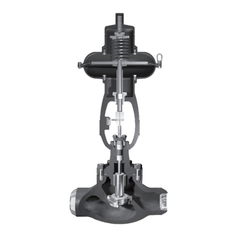
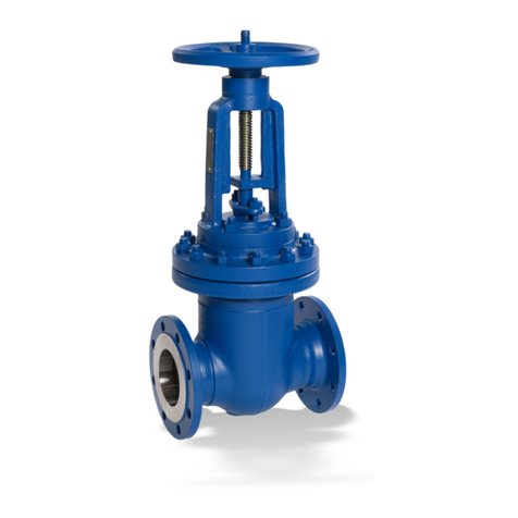
KSB MIL 76000 User manual

The following instructions should be thoroughly
reviewed and understood prior to installing, operating
or performing maintenance on this equipment.
Throughout the text, safety and/or caution notes will
appear and must be strictly adhered to, otherwise, serious injury
or equipment malfunction could result.
Instruction Manual
Purchase Order No : ___________________________________________
MIL 76000
High Pressure Letdown Control Valves

TABLE OF CONTENTS
1. Introduction........................................................................................................................2
2. General................................................................................................................................3
3. Unpacking...........................................................................................................................3
4. Installation ..........................................................................................................................4
5. Air Piping.............................................................................................................................4
6. Body Disassembly ................................................................................................................4
7. Maintenance / Repair ..........................................................................................................5
7.1 Guide Bush Removal.............................................................................................5
7.2 Lapping Seats .......................................................................................................5
7.3 Plug Stem Pinning................................................................................................6
7.3.1 Replacing Plug and Stem......................................................................6
7.3.2 Replacing Existing Stem only................................................................7
7.4 Packing Box..........................................................................................................7
8. Valve Body Reassembly.......................................................................................................8
Parts List............................................................................................................................10
9.
Note: Easily replaceable Pressure gauges for Air sets and externally mounted Pressure
gauges of positioners are normally dismantled, separately packed and bound to the
actuator yoke as a precaution against transit damages. This may be noted while
opening the boxes.
Warning: Do not lift large size valves by the actuator. Lifting lugs provided on the
actuators are for lifting the actuator alone.
1. Introduction
The following instructions should be thoroughly
reviewed and understood prior to installing,
operating or performing maintenance on this
equipment. Throughout the text, safety and/or
caution notes will appear and must be strictly
adhered to, otherwise, serious injury or
equipment malfunction could result.
MIL has a highly skilled Aftermarket
department available for start-up, maintenance
and repair of our valves and component parts.
Arrangements for availing their service can be
made through your local representative or
2

Aftermarket department. In addition, a
regularly scheduled training program is
conducted at our plant, to train customer
service and instrumentation personnel in the
operation, maintenance and application of MIL
Control Valves and Accessories. Also when
performing maintenance, please ensure that only
original MIL replacement parts are used. When
specifying parts, always include Serial Number
of the valve.
Caution: Skilled service personnel to be
engaged for start up, maintenance and
repair of the valve.
Caution: Always use original MIL
replacement parts while performing
maintenance.
2. General
MIL 76000 series high pressure letdown valves
are designed with angle body (side inlet and
bottom outlet) to handle compressible fluids
and flashing/two phase liquids effectively in
high pressure applications, without body/ trim
erosion, vibration and noise. Their angle design
provides flow surfaces that slopes down
permitting the valve to self-drain.
Tight Shut-off Class IV leakage is standard.
Optional constructions meet ANSI/FCI 70.2
Class V requirements.
Optional Low Emission Packing (Eco-lock) is
available to assure compliance with the fugitive
emission norms.
MIL 76000 has single and multi stage trim
options. Single stage design allows high flow
capacity with contoured plug and clamped seat
ring design. Body outlet flow passage is
protected by seat ring liner, which ensures long
life by limiting erosion of the body flow path
area. The liner is easily replaceable in case of
any wear
For higher pressure drop applications, Multi-
stage trims are employed. Multi-stage trim
incorporates a unique design, which integrates
the advantage of multi-stage pressure reduction
with gradually expanding area, to
reduce fluid velocity and the resultant noise
generation. Individual pressure drop stages in
the valve trim are designed to accommodate the
increased specific volume of the medium with
reduced fluid velocity. Due to the unique flow
path in the valve trim, the fluid is forced
through a zig-zag flow path, dissipating the
energy and maintaining low noise levels, when
the valve is in operation.These installation and
maintenance instructions apply to all sizes and
ratings of the MIL 76000 series control valves
regardless of the type of trim used.
Recommended spare parts required for
maintenance are listed in parts reference of page
9. The model number, size, rating and serial
number of valve are shown on the identification
tag located on the actuator. Refer to Figure 1 to
identify valve nomenclature.
Numbering System
Trim Type
0. Undefined
1. Single stage
2. Multi-stage
Body Series Body Style Trim
Characteristic
76. High pressure
Expanding area
letdown control
valve
0. Undefined
2.
Angle
1. Inline
0. Undefined
1. Linear
2. Mod %
76
Figure 1
3
3. Unpacking
Warning: Care must be exercised when unpacking the valve to prevent damage to the
accessories and component parts. Should any problems arise, contact your local
representative or MIL Aftermarket department. Do not remove end protection cover
before installation.

6
10
1
2
34
5
7
8
9A
9B
11
12
14
15
16
17
Caution: Where insulation of the valve
body is required, do not insulate the
valve bonnet. Take necessary protective
measures for personal safety.
5. Air Piping
Unless otherwise specified, the connection to the
actuator tubing shall be 1/4" NPT or ½" NPT.
Use the tubing equivalent or higher to the
connection size. Refer MIL valve specification
4. Installation
Caution: Before installing the valve in
the line, clean piping and flush the line
to remove all foreign material such as
welding chips, scale, oil, grease or dirt.
End flange gasket surfaces must be
thoroughly cleaned to ensure leak
proof joints.
To allow in-line inspection, maintenance or
removal of the valve without service
interruption, provide a manually operated stop
valve on either side of the MIL 76000 series
valve with a manually operated throttling valve
Caution: The valve must be installed so
that the controlled substance will flow
through the valve in the direction
indicated by the flow arrow located on
the body.
mounted in the by-pass line. (See figure 2)
Unless otherwise specified, the recommended
orientations is flow to close.
By-Pass Line By-Pass Valve
Main Line
Control Valve
Isolation Valve Isolation Valve
Warning : Do not exceed supply
pressure indicated on tag plate located
on the yoke of the actuator.
Figure 3 Single stage Trim Design
Multistage Trim Design
Figure 2
4
sheet of respective valves for more details. All
connection joints should be free of leaks.
6. Body Disassembly
Caution: New packing & gaskets sets
should be on hand before disassembling
the valve, since itis recommended that
new packing & gaskets be used during
reassembly.
Access to the internal components of the body
should be accomplished with the actuator
removed. To remove the actuator from the
body, refer to the appropriate actuator
instructions.

Warning: Prior to performing
maintenance on the valve, isolate the
valve and vent the process pressure.
Cut off supply air line and pneumatic
or electric signal line.
After removing the actuator, disassemble the
body using the following procedure:
A. If there is a leak detection connection on
the lateral NPT port of the bonnet,
disconnect this piping as well.
B. Remove body stud nuts (11).
C. Remove bonnet (9B), and plug stem (1)
and plug (14) sub-assembly together as
one unit.
D. Since the cage (17), seat ring (15) and seat
ring gasket (16) are held in place by the
bonnet, they may now be removed.
E. Remove packing flange stud nuts (3),
packing flange (4) and packing follower
(5).
Note : Spiral wound gaskets (12 & 16)
are standard in the 76000 series design
and it is imperative that new gaskets be
installed each time the valve is
disassembled.
F. Remove plug (14) and plug stem (1) sub-
assembly from the bonnet (9B).
Caution : Care must be taken to avoid
damage to the plug and plug guide.
G. Remove existing packing (7)
bonnet.
H. All components may now be inspected for
wear and service damage. After
determining the maintenance required,
proceed to the appropriate section of this
instruction manual.
in the
7. Maintenance & Repair
The purpose of this section is to assist
maintenance personnel by suggesting methods
of component maintenance, which is largely
dependent on the tools and machine shop
equipment available.
7.1 Guide Bush Removal
The guide bush (8) is press fit into the bonnet
and does not normally require replacement. If
necessary, it may be pulled or machined out.
When machining the bush out, care must be
taken to maintain proper dimensions and
tolerances in the bonnet. These will be
furnished upon request.
7.2 Lapping Seats
Lapping is the process of working the valve plug
against the seat ring with an abrasive to produce
a close fit. If valve leakage is excessive, lapping
becomes necessary. The plug and seat ring
seating surfaces should be free of large scratches
or other defects, and the contact surfaces of the
seats should be as narrow as possible. This may
require dressing both parts in a lathe. A good
grade of fine grinding compound is required for
the lapping operation.The compound should be
mixed with a small quantity of lubricant such as
graphite. This will slow the cutting rate and
prevent tearing of the seating surfaces. The
amount of lapping required depends on the
materials, condition of seating surfaces, and
accuracy of machining. lf a short period of
lapping does not visibly improve seating, there
Note : Lapping should produce a line
contact area, not the entire surface, due
to the difference in seat angles.The
seating surface angle of the plug is 28
degrees and the seat ring is 30 degrees
(relative to the centerline axis).
Caution : Before lapping, the plug and
stem sub-assembly must be concentric.
(See pinning operation, section 7.3).
T-Handle
Lock-Nut
5
is usually no advantage in continuing as
excessive lapping may result in rough seats. The
only, remedy is replacement or re-machining of
one or both parts. When lapping new plugs and
seat rings, begin with a medium compound and
finish with fine compound.
Figure 4

1. CIean body gasket surface areas.
2. Install a new seat ring gasket (16) and insert
seat ring (15) in the body.
Note : Gasket (16) is temporarily placed
to hold the seat ring during lapping. It is
imperative to use a new gasket or a test
part having the same geometrical
characteristics in order to insure the
correct position of the seat ring during
lapping.
This gasket (or similar part) can be kept after
lapping for future lapping purpose.
Caution: The gasket used for lapping
should not be reused for the body
reassembly.
3. Apply lapping compound at several spots
equally spaced around the seating area of
the seat ring.
4. Insert the cage (17) into the body (9A).
5. lnsert the stem and plug sub-assembly
carefully into the body until it is seated.
6. PIace bonnet (9B) on the body (9A).
Caution :Ensure that the seat ring (15),
cage (17) and bonnet (9B) are properly
aligned.
7. Fasten the bonnet to the body using four
body stud nuts (11) spaced equally apart.
Apply slight pressure and tighten evenly.
Caution : Do not tighten nuts to final
torque specifications at this time. The
bonnet is used temporarily for guiding
purposes only.
8. Insert two or three pieces of packing into
the packing box to assist in guiding the
stem and plug during lapping.
9. Screw a drilled and tapped rod with a T-
handle onto the plug stem and secure with
a locknut (see Figure 4).
Note : As an alternative, drill a hole
through a flat steel plate and fasten
to the plug stem using two locknuts.
10 . Apply slight pressure on the stem, and
rotate the stem in short oscillating strokes
(around 8 to 10 times). Repeat this step as
necessary.
Caution: Avoid over-lapping as this can
cause damage to the seating surface
rather than improve leakage
performance.
Note : The plug should be lifted and
turned 90° each time before repeating
Step (10). This intermittent lifting is
required to keep the plug and seat ring
concentric during lapping.
11. After completion of the lapping operation,
remove bonnet and internal parts. The
seating area of the seat ring and the plug
must be cleaned of all lapping compound
in preparation for reassembly.
7.3 PIug Stem Pinning
Plug stem pinning in the field may be
required for the following:
— Replacing of existing plug and stem, or
— Replacing of existing stem only
7.3.1 Replacing of Existing Plug and Stem
If it is necessary to replace the plug, then the
plug stem must be replaced at the same time.
The original pin hole in an existing stem will
not provide the necessary fit, and might
seriously impair the strength of the assembly.
A. Reference Marking on the Plug Stem
Measure the depth of the pilot recess in
the plug (Dimension X in Figure 5), and
make a reference mark on the plug stem at
the same distance from the thread.
Note: While pinning is being performed,
care must be taken not to damage the
seating surface or plug guide. Always
use a soft metal or plastic vice jaws with
cylindrical features to hold the plug
guide area (see Figure 5).
B. Screwing Stem to Plug
Hold the plug (with vise jaw assembly) in
a vise.
Lock two nuts against each other on the
end of the new plug stem, and screw the
stem solidly into the plug using a wrench
on the upper nut. When properly
assembled, the reference mark (see Section
A above) should be flushed with the end
6
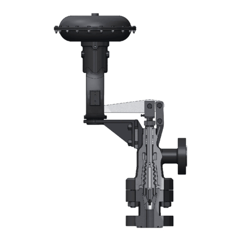
Figure 5
Plug Stem Pinning
Plug Stem
Dia. "B"
Pin Hole
Dia "C"
"D" "X"
in. in. in. in.
mm mm mm
½ 12.7 0.138 3.50 1.25 32.00 0.50 13
mm
5/8 15.88 0.138 3.50 1.55 39.50 0.63 16
3/4 19.05 0.197 5.00 1.88 47.50 0.75 19
1 25.40 0.197 5.00 2.50 63.50 1.00 26
Standard Valve
D
X
C Dia.
Reference Mark
B
X
of the plug guide.
C. Drilling the New Parts
If the plug is already fully drilled (typical
for 440C hardened stainless steel material
or solid stellite), then drill the stem to the
same diameter (diameter C in Figure 5) as
the plug shank hole.
If the plug guide area has a center mark,
ŸPlace the plug guide on a V-block and
use a suitable drill size to either:
ŸMatch the hole size in the plug, or
match diameter C (see Figure 5)
ŸDrill through the plug-stem assembly.
If the plug guide area does not have any
hole or any center mark,
ŸMeasure dimension D based on the
plug guide diameter and stem diameter
(see Figure 5).
ŸPlace the plug guide on a V-block, and
make a center mark on the plug guide
area using a center punch.
ŸDrill through the plug-stem assembly
using a suitable size drill bit.
In all cases after drilling : Remove any
burrs from the plug guide hole by making
a slight chamfer.
13
D. Pinning the Plug-Stem Assembly
Select the correct size pin based on the
plug guide diameter and stem diameter
(see Figure 5). Apply a small amount of
grease on the pin and hand assemble it
into the hole in the plug.
Press fit the pin into the hole using a
hammer. Complete the pinning operation
by taking care to ensure that the pin is
recessed by the same amount at both sides
(see Figure 5).
After the plug has been pinned, it should
be placed in a lathe to insure it is
concentric with the stem. If the assembly is
not running true, then the stem should be
placed in a collet with the plug guide
against it and the plug should be adjusted.
Alignment of plug stem can be performed
by means of a soft faced mallet.
7.3.2 Replacing of Existing Stem Only
A. Removing Existing Pin and Stem
Place the plug guide on a V-block and use
a drift punch to drive out the old pin.
Note : If it is necessary to drill out the
pin, use a drill bit slightly smaller than
the pin diameter.
Hold the plug guide in a vise.
Lock one nut against another at the end of
the plug stem. Using a wrench on the
lower nut, unscrew the stem from the
plug. The stem is removed by turning it
counterclockwise.
B. Screwing Stem to Plug
Refer to step B of the previous section on
'Replacing Plug and Stem'.
C. Drilling the New Stem
Place the plug guide on a V-block and use
a suitable size drill bit to drill the stem
(use the hole in the plug as a guide).
Note : If the hole in the plug guide has
been slightly damaged while removing
the old pin, choose a drill bit and a pin
with a slightly larger diameter than the
normal pin.
7

D. Pinning
Select the correct size pin based on the
plug guide diameter and pin hole diameter.
Proceed as described in part D of the
previous section 'Replacing Plug & Stem',
taking care not to damage the plug guide
area. Ensure plug stem alignment
following the pinning operation.
7.4 Packing Box (Figures 6 to 8)
Packing box maintenance is one of the principal
actions in routine servicing. Tightness of the
packing is maintained by packing compression.
Compression is achieved by evenly tightening
the packing flange nuts (3) against the packing
flange (4). Care must be taken not to over
tighten as this could
prevent smooth operation of the valve. If all
compression is used up and the valve leaks, then
new packing is required. The packing is
available as a set of lower and upper packing.
The height of the lower and upper packing set is
same for standard packing. Due to the
difference in the height for Eco-lock packing,
the packing sets are labeled as lower packing
and upper packing. The upper packing set will
be larger than lower packing set for Eco-lock.
Note: While replacing packing,
replace the upper packing set
completel
Caution : Valve must be isolated and the
pressure vented before performing
packing box maintenance.
Proceed as follows :
A. Disconnect the actuator stem from the
valve to maintain a gap to insert the
packing set
B. Loosen and remove packing flange nuts
(3).
C. Raise packing flange (4), and packing
follower (5) up the valve stem.
Note: They may be taped in place to
keep them out of the way before
proceeding.
D. By means of a hooked instrument, remove
packing (7) ensuring not to damage the
sealing surfaces of the packing box or plug
stem.
E. Replace packing (7) referring to Figure 6
for correct amount of packing to place
above the spacer.
Note : Assemble and compress rings one
at a time into packing box. If rings are
skive cut, the skive cut of each packing
ring must be placed about 120 degrees
apart.
Note: For any type packing do not
change the sequence of packing
arrangement. Use the packing as a set
only.
Note: MIL Ecolock packing (Fig 7) is a
high performance system to keep
fugitive emissions within allowable
limits. The packing is provided with the
inner packing and outer packing as a
set. It consists of V and double V
packing rings with varying density,
which is designed to prevent fugitive
emission from the packing effectively.
Caution: For Eco-lock packing, inner and
outer packing to be replaced as a set only.
F. Replace packing follower (5) and packing
flange (4).
G. Replace and tighten packing stud nuts (3).
Caution: Do not over-tighten.
H. Put valve back in service and tighten
packing only as much as is necessary to
stop leaking.
Note: In an emergency, string packing
may be used as a temporary repair
only. It must be replaced with the
correct packing as soon as possible.
Note: A spring loaded follower
assembly is used to maintain a constant
load on the packing, and is necessary
for thermal cycling applications. As the
definition of thermal cycling can vary,
and processes are potentially subject to
unpredicted thermal gradients. Both
standard and Eco-Lock systems are
available with the spring loaded
follower (Figure 8).
8

Figure 6
Standard Packing Box
Figure 7
Eco-Lock
Figure 8
Standard Packing Box With Live Loading
Plug Stem
Packing Nut
Packing Flange
Packing Follower
Packing Stud
Packing
Bonnet
Plug Stem
Packing Nut
Packing Flange
Packing Follower
Packing Stud
Eco-lock Packing
Bonnet
Plug Stem
Packing Nut
Packing Flange
Packing Follower
Packing Stud
Packing
Bonnet
Disc Spring
Caution: Packing box should be clean and free of burrs, rust, and any foreign matter.
Parts can be cleaned with denatured alcohol.
8. Valve Body Reassembly
After completion of the required maintenance,
the valve should be reassembled using the
following procedures:
Note: If any of the following steps
were completed during maintenance,
then proceed to the next step.
A. CIean all gasket mating surfaces.
B. Install seat ring gasket (16) and seat ring
(15).
Note: Spiral wound gaskets (12 & 16)
are standard in the 76000 series
design. It is imperative that a new
gasket be installed each time the valve
is disassembled.
C. Install cage (17).
D. Carefully install plug and stem assembly.
E. Install body gasket (12).
F. Assemble bonnet (9B) and body stud nuts
(11) and tighten. Bonnet must be
Note: Valve should be lapped before
final assembly. See Section 7.2 on
'Lapping Seats'.
positioned so the packing flange studs are
at 90° to the flow center line.
Caution: Care must be taken to ensure
that the cage, seat and bonnet are
properly aligned in the body. Tighten
nuts (11) until metal to metal contact is
obtained with proper bolt torque. Refer
to Figure 9 for proper bolt torque and
tightening sequence specifications.
Note: Cage should be installed in such a
way that, any one of the hole in the cage
(17) and body inlet bore shall be inline.
Figure 9 - Bolting Torques And Tightening Sequence
Valve size
(inch) ASME Rating Class Stud size Qty
(Nos)
Torque
(Nm)
1 to 2
150-600# M16x2 8 60
900-1500# M24x3 8 170
2500# M27x3 8 320
9

G. lnsert lower packing set (7) and lantern
ring or spacer (6). Refer to Section 7.4 for
proper packing assembly procedure for
standard or optional designs.
H. Install upper packing set and packing
follower (5) and packing flange (4).
I. lnstall packing flange stud nuts (3).
Caution: Do not overtighten (See
Section ‘7.4. Packing Box’).
J. For actuator assembly and plug stem
adjustment, proceed to the actuator
instruction manual.
1 Plug Stem ^
2 Packing Flange Stud
3 Packing Flange Nut
4 Packing Flange
5 Packing Follower
6 Packing Spacer
7 Gland Packing ^
8 Guide Bush
9A Body
Part List
Sl No
9B Bonnet
10 Body Stud
11 Body Nut
12 Body Gasket ^
13 Plug Pin ^
14 Valve Plug ^
15 Seat Ring ^
16 Seat Ring Gasket ^
17 Retaining Cage
Part List
Sl No
Parts List
6
10
1
2
34
5
7
8
9A
9B
11
12
14
15
16
17
^ Recommended Spare Parts
10


INS/76000/REV-A/02-2018/ © KSB MIL Controls Limited 2018. Subject to technical modification without prior notice.
KSB MIL Controls Limited
Meladoor, Annamanada, Pin - 680741
Thrissur District, Kerala, India
Tel. +91 480 2695700, Fax. +91 480 2890952
E-mail: [email protected], www.ksb-mil.com
You can also visit us at:
www.ksb.com/socialmedia
IMPORTANT
In normal process control applications, expected life cycle of a control valve is 25 years with periodic
maintenance and replacement of wear parts. We recommend inspection of valves in critical loops
during all plant shutdowns.
Soft parts like gland packing, gaskets, seal rings etc are recommended to be replaced with OEM parts
every time valve is opened for maintenance. Metallic Wear parts like plug, seat ring, cages etc are to
be inspected in the event of performance deterioration and should be replaced if found necessary.
Damage, if any, noticed to valve body and bonnet also should be replaced or repaired.
After the life-cycle, we recommend to dispose the parts as per your established procedures, through
approved agencies only.
Table of contents
Other KSB Control Unit manuals

KSB
KSB Controlmatic E.2 Installation instructions

KSB
KSB STAAL 40 AKD User manual

KSB
KSB BOAX-B Series User manual

KSB
KSB BOA-SuperCompact User manual

KSB
KSB BOA-Control PIC User manual

KSB
KSB BOA-R User manual

KSB
KSB MSE User manual

KSB
KSB ECOLINE VA 40 User manual

KSB
KSB MIL 41000 Installation instructions

KSB
KSB BOA-H Mat P Installation instructions
Popular Control Unit manuals by other brands

Rotex
Rotex 30138 Operating & maintenance instructions

GroupGets
GroupGets PureThermal 2 manual

FujiFilm
FujiFilm IGBT Applications manual

Nice
Nice D-Pro Action Series Instructions and warnings for installation and use

Fibocom
Fibocom SC138-NA Series Hardware guide

Toto
Toto TLE05701H Installation and owner's manual