6
Installation
We recommend to fit shut-
off valves in the pipeline on both sides of the
strainer, so that the strainer can be replaced or cleaned without having
to drain the entire system. Strainers shall be installed with suffi
clearance
for removing the strainer insert. In both horizontal and vertical
pipes, we recommend to install the strainer with the strainer insert
hanging downwards to facilitate cleaning. Compliance with the
directional arrow is essential. On strainer
s with magnetic insert we
recommend to remove the entire cover to clean the magnet.
6.1 General
As a rule, the engineering contractor, construction company or
operator/user are responsible for the positioning and installation
the valves.
Planning and
installation errors may impair the reliable function of the
valves and pose a substantial safety hazard.
following requirements is of particular importance:
Please note: When replacing the strainer insert make sure that
the weld of th
e insert is not located in the strainer outlet port, so as
to attain an optimum (high) Kv value.
Caution
The piping must be laid such that detrimental thrust
and torsional forces are kept away from the valve
body (1) during installation and operation to avoid both leakage and
damage to the body.
Valves with separate throttling valve disc
installed in
such a way that the pressure to be sealed off lies
beneath the disc, to ensure a reliable throttling effect.
Caution
The caps on the connection ports shall be removed
immediately prior to installation.
For higher differential pressures integral throttling valve disc-
stem connections are required. In such
to install the
Valves so that the pressure lies above the disc.
When painting the pipelines and valves, do not apply paint to
the bolts, stems and plastic components(valve function will be
impaired). If construction work is still in progress, the valves must be
protected against dust
, sand and building material (cover with suitable
material).
If you have questions concerning optimum valve selection
or
permissible differential pressures for valves with throttling
discs, please contact the valve manufacturer.
Do not use valve handwheels as footholds.
Drainage, vent or manual start-up pipes are normally fitted with
valve combinations consisting of a shut-off valve (pressure
beneath the disc)
For safety reasons, valves and piping systems operated at high
(>50 °C) or low (< 0 °C) temperatures must be insul ated, or a
and a throttling valve (integral throttling disc—stem
connection, pressure above the disc).
warning sign must point out the risk of personal injury involved when
touching the hot or cold components
.
Valves with external moving elements must be fitted with protective
covers, or other suitable measures must be taken to prevent accidents.
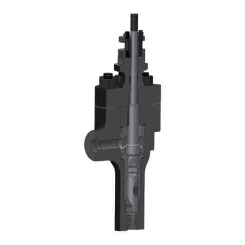
Valves with pilot plug are always installed so that the pressure
to be sealed off lies above the plug.
Valves used as dead-end valves in a pipeline should be
protected against unauthorized or unintentional opening, to
If the valves are to be used as dead-end valves, double shut-off
should be ensured for safety reasons.
prevent damage to property and/or personal injury.
6.3 Installation instructions
6.2 Installation position
6.3.1 Flanged valves
The mating flange faces must be clean and undamaged.
The valve bodies are marked with an arrow indicating flow direction, if
necessary. The valves must be installed such that the flow direction of
the fluid corresponds to the direction shown by the arrow cast on the
The gaskets on the mating flangesmust be properly
centered. Only fasteners and sealing elements made
of approved
valve body. If no directional arrow is cast on the valve body, the valve
can be installed in any position.
materials shall be used. For the flange connection between valve
and pipe use all flange bolt holes provided.
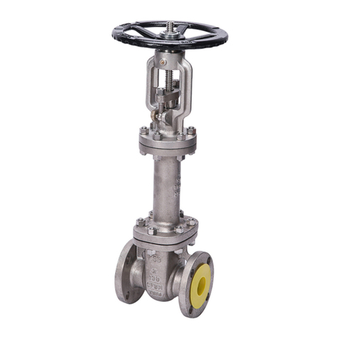
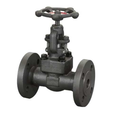
Shut-off valves can be installed in any po
sition. However, the best
installation position is with the stem pointing vertically upwards. Valves
with bellows should not be installed with the stem pointing
downwards,
if possible, to prevent dirt deposits between the folds of
the bellows.
Use suitable tools to tighten the bolts evenly and crosswise at
the permissible torques.
6.3.2 Welding instructions
Shut-
off valves must be installed in the line so as to ensure that the fluid
enters the valve beneath the disc and flows out above the disc.
However,
they can also be installed in lines with alternating flow. If the
valves are to be used for throttling applications, a throttling valve disc
must be used. For flow incidence on throttling valve discs please refer
to the respective type series booklets. If
in doubt, please contact the
KSB factory.
Responsibility for welding the valves into the piping and for any
heat
treatment required lies with the respective contractor or
the plant operator.
Caution
When welding valves with butt or socket weld
ends into the piping or when performing welding
pipeline after
the valves have been installed (pipeline installation)
make
sure that no contamination enters the valve body and stays
there, to
prevent damage to the seat/disc interface or stem
Caution
When welding the valve into the pipeline, take
special
precautions e.g. welding in several steps,
so that the
temperature rise in the middle of the valve body does not exceed
the max. permissible operating temperature.
in 'open' position during welding.
6.2.2 Non-return valves
Caution
The welding cable (opposite pole) must not be
attached to functional valve elements, to
prevent scorching.
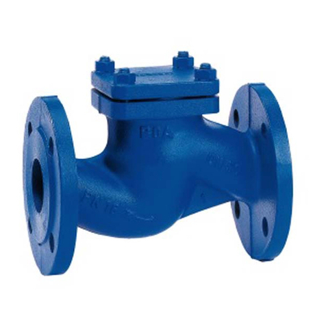
To ensure proper operation, non-return valve
s must always be installed
in such away tha the fluid enters the valve beneath the check
valve disc (2). When equipped with a spring (37
pipes with upward flow and pipes with downward flow.
On valves with socket weld ends, the
the
applicable technical code must be complied with. A gap
between the
pipe end and the socket base will prevent
impermissiblestresses inthe weld.
Non-return valves without closing spring (37) shall only be installed in
tal position with the cover pointing upwards in horizontal pipes.
6.2.3 Strainers
6.4 Valves with actuator
Strainers shall always be installed in such a way that the fluid flows
through the strainer insert from the inside towards the outside
(cage effect of the strainer insert).
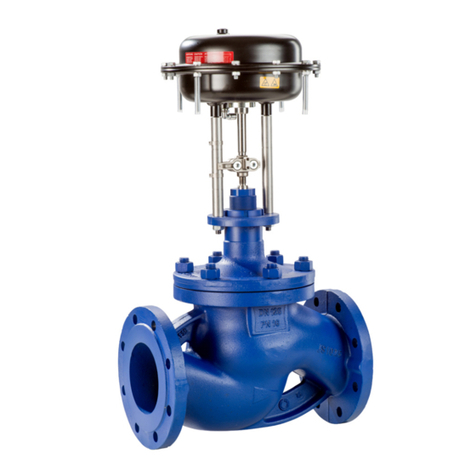
Valves with transmission gear and/or actuators must be installed
with the stem in vertical position, if possible. If this requirement
cannot be
met, adequately support the actuator on site or consult
the manufacturer.
10
