KSB PumpDrive 2 Eco User guide

Self-cooling Motor-independent Frequency
Inverter
PumpDrive 2 Eco
Application Guide

Version 1.4
Application Guide PumpDrive 2 Eco
2016-10-20
2016-11-11 PDrv2-Eco_Application_Guide_rev_1_4.docx
Page 1 of 48
Application Guide
PumpDrive 2 Eco
The use cases in the application guide are only typical examples for training purposes. The examples are not cus-
tomer specific solutions. The examples are not binding and can be incomplete. The examples do not cover all possi-
ble eventualities. The examples do not cover all design details and variants, nor do they cover all scenarios and situ-
ations that may arise during installation, operation or maintenance. The application guide is not replacing the oper-
ating manual. In any case of divergence the operating manual has higher priority. The operator must take care
about the appropriate operation referring to the operating manual. The examples do not excuse from the save op-
erating, installation and service. Changes of this application guide will be done without announcement.

Version 1.4
Application Guide PumpDrive 2 Eco
2016-10-20
2016-11-11 PDrv2-Eco_Application_Guide_rev_1_4.docx
Page 2 of 48
1. Pre-Conditions..............................................................................................................................3
1.1.1 Pump characteristc curve ...................................................................................................................................... 6
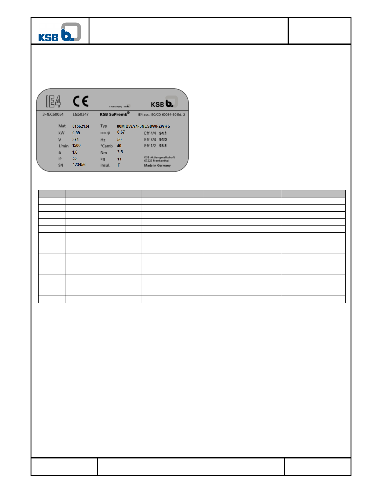
1.1.2 Parameterization of Motor data............................................................................................................................. 7
2. Single pump..................................................................................................................................8
2.1 Single pump –Open loop control...........................................................................................................8
2.1.1 Open loop control: control value at display.......................................................................................................... 8
2.1.2 Open loop control: control value by external signal 0…10V ............................................................................... 9
2.1.3 Open loop control: control value by external signal 4…20mA ...........................................................................10
2.1.4 Open loop control: digital motor potentiometer...................................................................................................11
2.2 Single pump –closed loop control........................................................................................................12
2.2.1 Closed loop control: Differential pressure with PumpMeter (Modbus)...............................................................12
2.2.2 Closed loop control: differential pressure with sensor 4…20mA ........................................................................13
2.2.3 Closed loop control: differential pressure with sensor 4…20mA set point via analog input ...............................14
2.2.4 Closed loop control: differential pressure with 2 pressure sensors 4...20 mA .....................................................15
2.2.5 Closed loop control: Sensorless differential pressure control..............................................................................16
2.2.6 Closed loop control: pressure with pressure sensor 4...20 mA ............................................................................17
2.2.7 Closed loop control: Pressure with PumpMeter (Modbus)..................................................................................18
2.2.8 Closed loop control: Pressure with Pressure sensor 0...10 V...............................................................................19
2.2.9 Closed loop control: Pressure, Set point (closed loop) at analog input 0…10V ..................................................20
2.2.10 Closed loop control: constant level at low pressure side with submersible sensor 4…20mA.........................21
2.2.11 Closed loop control: temperature with thermometer 4…20mA ......................................................................22
2.2.12 Closed loop control: Flow rate with flow rate sensor 4…20mA .....................................................................23
3. Double pump...............................................................................................................................24
3.1 Double pump –Open loop control.......................................................................................................24
3.1.1 Open loop control: control value at display.........................................................................................................24
3.1.2 Open loop control: control value with external signal.........................................................................................26
3.2 Double pump –closed loop control......................................................................................................28
3.2.1 Closed loop control non redundant: differential pressure with PumpMeter (Modbus) –typical application ......28
3.2.2 Closed loop control redundant: differential pressure with PumpMeter (Modbus)...............................................30
3.2.3 Closed loop control redundant: Discharge pressure with sensor 4…20mA and PumpMeter each pump ............32
3.2.4 Closed loop control redundant: Discharge pressure with pressure sensor 4…20mA via M12 ............................35
4. Pump functionality......................................................................................................................38
4.1 Closed loop control................................................................................................................................38
4.1.1 Closed loop control: dynamic differential pressure set point compensation based on flow rate estimation ........38
4.1.2 Closed loop control: dynamic differential pressure set point compensation based on speed...............................40
4.1.3 Open loop control: 1 fix speed selected by digital switches or variable speed via analog signal ........................41
4.1.4 Closed loop control: sleep Mode .........................................................................................................................42
5. M12 Cable....................................................................................................................................43
5.1 Bus cable for connecting PumpMeter to the M12-Module................................................................43
5.2 Bus cable for Double- and Multi Pump Operation.............................................................................44
5.3 Crosslink cable.......................................................................................................................................45
5.4 M12 Cable for fieldbus module Modbus RTU....................................................................................46
6. Project .........................................................................................................................................47
7. Other documents........................................................................................................................48

Version 1.4
Application Guide PumpDrive 2 Eco
2016-10-20
2016-11-11 PDrv2-Eco_Application_Guide_rev_1_4.docx
Page 3 of 48
1. Pre-Conditions
-The motor data are set according to the operating manual.
-The motor control is correct selected and suits to the motor.
-The pump curves are stored in the drive.
Pre-settings from production
Pumps with PumpDrive are delivered with the following pre-settings:
Motor data
Motion control according to motor type
Pre-setting of PumpMeter including sensors
Pump curves
Type series
Etaline / Etaline Z
Etanorm, Etabloc, Etachrom
Multitec, Movitec, Sewatec
Retrofit Drive
PumpDrive spare part
selection
EasySelect
EasySelect
EasySelect
Material number
Motor data
preset
preset
Preset
-
Asynchronous motor
Vector ASM
Vector ASM
Vector ASM
-
SuPremE
Vector SuPremE
Vector SuPremE
Vector SuPremE
Vector SuPremE
with PumpMeter
Closed loop control: Differen-
tial pressure and sensors pre-
set
Closed loop control: pressure p
constant and sensors preset
-
-
without PumpMeter
Open-loop Control
Open-loop Control
Open-loop Control
Open-loop Control
Pump curve
preset
preset
-
-
Setpoint
with PumpMeter: preset
-
-
Retrofit PumpDrives, which will be selected in EasySelect, will be delivered only with motor data (work is in progress). The pump curves
must be parameterized on site, can be uploaded from PumpMeter, can be set from ServiceTool or display.
PumpDrives (spare parts), which are ordered by material numbers are not parameterized in the production.
Using a 0/4…20mA or 0/2…10V Sensor for control a PumpMeter can be used as internal sensor in parallel. PumpMeter used as internal
sensor improves the flow estimation.

Version 1.4
Application Guide PumpDrive 2 Eco
2016-10-20
2016-11-11 PDrv2-Eco_Application_Guide_rev_1_4.docx
Page 4 of 48
L1 L2 L3
LINE PE U V W
MOTOR
PTC
MOTOR
PE -
L1
L2
L3
N
PE
1234
5
M
3~
BR
+
66
L1 L2 L3
LINE PE U V W
MOTOR
PTC
MOTOR
PE -
L1
L2
L3
N
PE
1234
5
M
3~
BR
+
66
L1 L2 L3
LINE
PE U V W
MOTOR
PTC
MOTOR
PE -
L1
L2
L3
N
PE
12
3
4
5M
3~
BR
+
6
Connecting mains and motor
Size A (0,37 kW –1,5 kW)
Size B (2,2 kW –4 kW)
Size C (5,5 kW –11 kW)
Nr.
Function
1
Mains connection
2
Motor connection
3
PTC connection
4
Brake
5
Motor PTC
6
Jumper for IT mains
Nr.
Function
1
Mains connection
2
Motor connection
3
PTC connection
4
Brake
5
Motor PTC
6
Jumper for IT mains
Nr.
Function
1
Mains connection
2
Motor connection
3
PTC connection
4
Brake
5
Motor PTC
6
Jumper for IT mains

Version 1.4
Application Guide PumpDrive 2 Eco
2016-10-20
2016-11-11 PDrv2-Eco_Application_Guide_rev_1_4.docx
Page 5 of 48
2 4 3 2
1/min
P 1.1.1.
0 0 0 0
P 1.1.1.
Standard Display
For the parameterization of the following applications the user must be logged in Customer Level.
Customer Login in Favourite Menu:
By pressing the button OK Taste the user selects the Favourite Menu, where the main parameters can be changed.
By pressing up and down buttons, the user can navigate through the Favourite Menu.
Settings:
By pressing ESC and OK at the same time, the user selects the first menu level, where he can navigate through the different
menus and parameters.
Main Screen
Favourite Menu
First Parameter: 1-1-1 Login
Type in PIN: 0000
4 x
A screw driver is displayed after
successful login
Favourite Menu

Version 1.4
Application Guide PumpDrive 2 Eco
2016-10-20
2016-11-11 PDrv2-Eco_Application_Guide_rev_1_4.docx
Page 6 of 48
1.1.1 Pump characteristic curve
The pump characteristic curve for an Etaline 040-040-160 with full impeller diameter 174 has to been set manually. The values for the
pump characteristic curves are readout of the type series booklet at nominal speed of the pump with impeller diameter 174.
Nr.
Parameter
Change value to
Pre-settings by factory 2)
Changeable by
3-4-3-1
Flow Rate Q_0
0.0 [m³/h]
Preset: 0,0 m3/h
ServiceTool
3-4-3-2
Flow Rate Q_1
10.0 [m³/h]
Preset: 10,1 m3/h
ServiceTool
3-4-3-3
Flow Rate Q_2
20.0 [m³/h]
Preset: 20,3 m3/h
ServiceTool
3-4-3-4
Flow Rate Q_3
30.0 [m³/h]
Preset: 30,5 m3/h
ServiceTool
3-4-3-5
Flow Rate Q_4
40.0 [m³/h]
Preset: 40,6 m3/h
ServiceTool
3-4-3-6
Flow Rate Q_5
50.0 [m³/h]
Preset: 50,8 m3/h
ServiceTool
3-4-3-7
Flow Rate Q_6
60.0 [m³/h]
Preset: 60,9 m3/h
ServiceTool
3-4-3-8
Flow Rate Q_opt
35.0 [m³/h]
Preset: 35,0 m3/h
ServiceTool
3-4-3-9
Pump Input Power P_0
1.50 [kW]
Preset: 1,52 kW
ServiceTool
3-4-3-10
Pump Input Power P_1
2.50 [kW]
Preset: 2,62 kW
ServiceTool
3-4-3-11
Pump Input Power P_2
3.50 [kW]
Preset: 3,73 kW
ServiceTool
3-4-3-12
Pump Input Power P_3
4.50 [kW]
Preset: 4,64 kW
ServiceTool
3-4-3-13
Pump Input Power P_4
5.20 [kW]
Preset: 5,39 kW
ServiceTool
3-4-3-14
Pump Input Power P_5
5.70 [kW]
Preset: 5,97 kW
ServiceTool
3-4-3-15
Pump Input Power P_6
6.00 [kW]
Preset: 6,34 kW
ServiceTool
3-4-3-16
Head H_0
42.00 [m]
Preset: 43,06 m
ServiceTool
3-4-3-17
Head H_1
41,80 [m]
Preset: 42,89 m
ServiceTool
3-4-3-18
Head H_2
40.00 [m]
Preset: 41,41 m
ServiceTool
3-4-3-19
Head H_3
36.00 [m]
Preset: 37,48 m
ServiceTool
3-4-3-20
Head H_4
31.00 [m]
Preset: 32,45 m
ServiceTool
3-4-3-21
Head H_5
25.00 [m]
Preset: 25,88 m
ServiceTool
3-4-3-22
Head H_6
16.00 [m]
Preset: 16,88 m
ServiceTool
3-4-3-30
Low Flow Limit Flow Rate in %
Qopt
30 [%]
Preset
ServiceTool
2) Pre-settings for completely assembled pump, motor, drive

Version 1.4
Application Guide PumpDrive 2 Eco
2016-10-20
2016-11-11 PDrv2-Eco_Application_Guide_rev_1_4.docx
Page 7 of 48
1.1.2 Parameterization of Motor data
A PumpDrive 2 is parameterized for a 2 pole SuPremE Motor. The pump rotation is clockwise.
Name plate of motors:
Nr.
Parameter
Change value to
Pre-settings by factory 2)
Changeable by
3-2-1-1
Nominal Motor Power
0.55 [kW]
Preset: 0.55 [kW]
ServiceTool, Display
3-2-1-2
Nominal Motor Voltage
374 [V]
Preset: 400 [V]
ServiceTool, Display
3-2-1-3
Nominal Motor Frequency
50.0 [Hz]
Preset: 50.0 [Hz]
ServiceTool, Display
3-2-1-4
Nominal Motor Current
1.60 [A]
Preset: 1.60 [A]
ServiceTool, Display
3-2-1-5
Nominal Motor Speed
1500 [1/min]
Preset: 1500 [1/min]
ServiceTool, Display
3-2-1-6
Nominal Cos Phi Value
0.67
Preset: 0.57
ServiceTool, Display
3-2-2-1
Minimum Motor Speed
500 [1/min]
Preset: 500 [1/min]
ServiceTool, Display
3-2-2-2
Maximum Motor Speed
1500 [1/min]
Preset: 1500 [1/min]
ServiceTool, Display
3-2-3-1
PTC Data Analysis
1 = ON
Preset: ON
ServiceTool, Display
3-2-3-2
Thermal Motor Protection Be-
haviour
Non-self-acknowledging
Preset: Non-self-acknowledg-
ing
ServiceTool
3-2-4
Motor Direction of Rotation
0 = Clockwise4)
Preset: Clockwise
ServiceTool, Display
3-3-1
Motor Control Method
Vector SuPremE
Preset: SuPremE Vector Con-
trol
ServiceTool
3-3-4-1
Update Motor Parameters
Run
Preset
ServiceTool
2) Pre-settings for completely assembled pump, motor, drive
4) Pump dependent

Version 1.4
Application Guide PumpDrive 2 Eco
2016-10-20
2016-11-11 PDrv2-Eco_Application_Guide_rev_1_4.docx
Page 8 of 48
16
18
+24V
DI
18
DO 1616
DI-EN
+24V
GND
DI3
DI2
DI1
+24V
DICOM
AO-GND
AO
AIN2
NO
+24V
GND
COM
+24V
B1
B2
B3
B4
B5
B6
B7
B8
B9
B10
A1
A2
A3
A4
A5
A6
A7
A8
A9
A10
GND
GND
AIN1
+24V
17 GND 1717
GND
DO 1111
11
2. Single pump
2.1 Single pump –Open loop control
2.1.1 Open loop control: control value at display
A fixed speed of 2000 1/min should be set on the display. The nominal speed of the 2 pole motor is 2950 1/min.
2000 1/min
Nr.
Parameter
Change value to
Pre-settings by factory
2)
Changeable by
3-6-1
Type of Control
0 = OFF (Open-loop Con-
trol)
preset
ServiceTool, Display
3-2-2-1
Minimum Motor Speed
500 [1/min]
preset
ServiceTool, Display
3-2-2-2
Maximum Motor Speed
2950 [1/min]
preset
ServiceTool, Display
1-3-3
Control Value (Open-loop Control)
2000 [1/min]
motor specific
ServiceTool, Display
3-8-6-1
Digital Input 1 Function
System Start1)
preset
ServiceTool
1) Digital Input 1 is set as at the factory as system start. If a digital input is set as system start, the parameter 1-3-1 System start is auto-
matically without function (see control point concept in operating manual)
2) Pre-settings for completely assembled pump, motor, drive
Nr.
Function
16
Enable power electronic
17
Ground for digital inputs
11
System start with DI11)
18
Alarm
PDrv 2 Eco
Or local
Or PLC
drive

Version 1.4
Application Guide PumpDrive 2 Eco
2016-10-20
2016-11-11 PDrv2-Eco_Application_Guide_rev_1_4.docx
Page 9 of 48
16
17
18
+24V
DI
18
DO
GND
16
17
16
17
GND
2 2
AO: 0...10V
0...10V
11
DI-EN
+24V
GND
DI3
DI2
DI1
+24V
DICOM
AO-GND
AO
AIN2
NO
+24V
GND
COM
+24V
B1
B2
B3
B4
B5
B6
B7
B8
B9
B10
A1
A2
A3
A4
A5
A6
A7
A8
A9
A10
GND
GND
AIN1
+24V
DO 11
0V (GND) AO: OUT 0V(GND)
11
2.1.2 Open loop control: control value by external signal 0…10V
A fixed speed of 2000 1/min should be given by an external signal 0…10V at analog input 1.
2000 1/min is equal to 6,78 V when using a 2-pole motor with a nominal speed of 2950 1/min.
Information: the set point can’t be lower than the minimum speed.
6,78V
2000 1/min
2
Nr.
Parameter
Change value to
Pre-settings by factory
2)
Changeable by
3-6-1
Type of Control
0 = OFF (Open-loop Control)
preset
ServiceTool, Display
3-2-2-1
Minimum Motor Speed
500 [1/min]
preset
ServiceTool, Display
3-2-2-2
Maximum Motor Speed
2950 [1/min]
preset
ServiceTool, Display
3-8-1-1
Analog Input 1 Signal
4 = 0…10V
0 = Off
ServiceTool, Display
3-8-1-2
Analog Input 1 Function
1 = Setpoint/Control value
(Auto)
0 = No Function
ServiceTool, Display
3-8-1-3
Analog Input 1 Lower Limit
0 [1/min]
-
ServiceTool, Display
3-8-1-4
Analog Input 1 Upper Limit
2950 [1/min]
-
ServiceTool, Display
3-8-6-1
Digital Input 1 Function
System Start1)
preset
ServiceTool
1) Digital Input 1 is set as at the factory as system start. If a digital input is set as system start, the parameter 1-3-1 System start is auto-
matically without function (see control point concept in operating manual)
2) Pre-settings for completely assembled pump, motor, drive
Nr.
Function
16
Enable power electronic
17
Ground for digital inputs
11
System start with DI11)
2
Set point (open loop): external signal0...10V
18
Alarm
PDrv 2 Eco
Or local
Or PLC
drive

Version 1.4
Application Guide PumpDrive 2 Eco
2016-10-20
2016-11-11 PDrv2-Eco_Application_Guide_rev_1_4.docx
Page 10 of 48
16
17
18
+24V
DI
18
DO
GND
16
17
16
17
GND
2 2
AO: 4...20mA
4...20mA
11
DI-EN
+24V
GND
DI3
DI2
DI1
+24V
DICOM
AO-GND
AO
AIN2
NO
+24V
GND
COM
+24V
B1
B2
B3
B4
B5
B6
B7
B8
B9
B10
A1
A2
A3
A4
A5
A6
A7
A8
A9
A10
GND
GND
AIN1
+24V
DO 11
0V (GND) AO: OUT 0V(GND)
15
AIN
GND
11
14,85 mA
2000 1/min
2
2.1.3 Open loop control: control value by external signal 4…20mA
A fixed speed of 2000 1/min should be given by an external signal 4…20mA at analog input 1.
The feedback of the speed should be send by analog output to a PLC.
2000 1/min is equal to 14,85 mA when using a 2-pole motor with a nominal speed of 2950 1/min (16mA / 2950 rpm * 2000 rpm + 4 mA
= 14,85 mA). Information: the set point can’t be lower than the minimum speed
Nr.
Parameter
Change value to
Pre-settings by fac-
tory 2)
Changeable by
3-6-1
Type of Control
0 = OFF (Open-loop Control)
preset
ServiceTool, Display
3-2-2-1
Minimum Motor Speed
500 [1/min]
preset
ServiceTool, Display
3-2-2-2
Maximum Motor Speed
2950 [1/min]
preset
ServiceTool, Display
3-8-1-1
Analog Input 1 Signal
1 = 4…20mA
0 = Off
ServiceTool, Display
3-8-1-2
Analog Input 1 Function
1 = Setpoint/Control value
(Auto)
0 = No Function
ServiceTool, Display
3-8-1-3
Analog Input 1 Lower Limit
0 [1/min]
-
ServiceTool, Display
3-8-1-4
Analog Input 1 Upper Limit
2950 [1/min]
-
ServiceTool, Display
3-8-7-1
Assignment 1 Analog Output 1
Motor speed
preset
ServiceTool
3-8-6-1
Digital Input 1 Function
System Start1)
preset
ServiceTool
1) Digital Input 1 is set as at the factory as system start. If a digital input is set as system start, the parameter 1-3-1 System start is auto-
matically without function (see control point concept in operating manual)
2) Pre-settings for completely assembled pump, motor, drive
Nr.
Function
16
Enable power electronic
17
Ground for digital inputs
11
System start with DI11)
15
Analog output: speed
2
Set point (open loop): external signal4...20mA
18
Alarm
PDrv2 Eco
Or local
Or PLC
drive

Version 1.4
Application Guide PumpDrive 2 Eco
2016-10-20
2016-11-11 PDrv2-Eco_Application_Guide_rev_1_4.docx
Page 11 of 48
16
17
18
+24V
DI
18
DO
GND
16
17
16
17
GND DO
DO 12
13
12
13
11
DI-EN
+24V
GND
DI3
DI2
DI1
+24V
DICOM
AO-GND
AO
AIN2
NO
+24V
GND
COM
+24V
B1
B2
B3
B4
B5
B6
B7
B8
B9
B10
A1
A2
A3
A4
A5
A6
A7
A8
A9
A10
GND
GND
AIN1
+24V
DO 11
11
2.1.4 Open loop control: digital motor potentiometer
A fixed speed of 2000 1/min should be changeable by the digital inputs with an increment of 10 [1/min].
13
12
+/- 2000 1/min
Nr.
Parameter
Change value to
Pre-settings by factory
2)
Changeable by
3-6-1
Type of Control
0 = OFF (Open-loop Control)
preset
ServiceTool, Display
3-2-2-1
Minimum Motor Speed
500 [1/min]
preset
ServiceTool, Display
3-2-2-2
Maximum Motor Speed
2950 [1/min]
preset
ServiceTool, Display
1-3-3
Control Value (Open-loop Control)
2000 [1/min]
motor specific
ServiceTool, Display
3-8-6-2
Digital Input 2 Function
Potentiometer Auto -
No Function
ServiceTool
3-8-6-3
Digital Input 3 Function
Potentiometer Auto +
No Function
ServiceTool
3-6-6-2
Speed Change Increment
10 [1/min]
preset
ServiceTool
3-8-6-1
Digital Input 1 Function
System Start1)
preset
ServiceTool
1) Digital Input 1 is set as at the factory as system start. If a digital input is set as system start, the parameter 1-3-1 System start is auto-
matically without function (see control point concept in operating manual)
2) Pre-settings for completely assembled pump, motor, drive
Nr.
Function
16
Enable power electronic
17
Ground for digital inputs
13
DI3: Increase speed
12
DI2: Decrease speed
11
System start with DI11)
18
Alarm
PDrv 2 Eco
Or local
Or PLC
drive

Version 1.4
Application Guide PumpDrive 2 Eco
2016-10-20
2016-11-11 PDrv2-Eco_Application_Guide_rev_1_4.docx
Page 12 of 48
16 DO 1616
DI-EN
+24V
GND
DI3
DI2
DI1
+24V
DICOM
AO-GND
AO
AIN2
NO
+24V
GND
COM
+24V
B1
B2
B3
B4
B5
B6
B7
B8
B9
B10
A1
A2
A3
A4
A5
A6
A7
A8
A9
A10
GND
GND
AIN1
+24V
18
+24V
DI
18
17 GND 17
17GND
11 DO 1111
70
80
4
DC
BA
2.2 Single pump –closed loop control
2.2.1 Closed loop control: Differential pressure with PumpMeter (Modbus)
A constant differential pressure of 4 bar is needed. PumpMeter is used as a differential pressure sensor in the measurement range of -1
… 10 bar. PumpMeter is connected by Modbus to the M12 Module of the drive. The set point is given by the display.
Δp4
A
Nr.
Parameter
Change value to
Pre-settings by factory 2)
Changeable by
3-6-1
Type of Control
3 = Differential Pressure
preset - see chapter 1
ServiceTool, Display
3-11-2-1
Minimum Pressure
-1.00 [bar]
preset
ServiceTool
3-11-2-2
Maximum Pressure
10.00 [bar]
preset
ServiceTool
3-11-2-3
Pressure Unit
bar
preset
ServiceTool
1-3-2
Setpoint (Closed-loop Control)
4.00 [bar]
preset acc. specified Q,H
ServiceTool, Display
3-8-4-1
Function M12 Module Input A
1 = PMtr Suction/Dis-
charge Pressure
preset
ServiceTool, Display
3-8-6-1
Digital Input 1 Function
System Start1)
preset
ServiceTool
1) Digital Input 1 is set as at the factory as system start. If a digital input is set as system start, the parameter 1-3-1 System start is auto-
matically without function (see control point concept in operating manual)
2) Pre-settings for completely assembled pump, motor, drive and PumpMeter
Nr.
Function
16
Enable power electronic
17
Ground for digital inputs
11
System start with DI11)
18
Alarm
4
Actual value: tailor-made bus cable for the connection of Pump-
Meter to the M12 Module (color: black, female: straight, male: an-
gled)
Nr.
Function
70
M12 Module: Double and multi pump operation
80
M12 Module: PumpMeter
A
M12 Module female A: connection PumpMeter (Modbus)
B
-
C
-
D
-
PDrv 2 Eco
Or local
Or PLC
drive

Version 1.4
Application Guide PumpDrive 2 Eco
2016-10-20
2016-11-11 PDrv2-Eco_Application_Guide_rev_1_4.docx
Page 13 of 48
16 DO 1616
18
+24V
DI
18
2
DI-EN
+24V
GND
DI3
DI2
DI1
+24V
DICOM
AO-GND
AO
AIN2
NO
+24V
GND
COM
+24V
B1
B2
B3
B4
B5
B6
B7
B8
B9
B10
A1
A2
A3
A4
A5
A6
A7
A8
A9
A10
GND
GND
AIN1
+24V
17 GND 1717
GND
11 DO 11
11
2.2.2 Closed loop control: differential pressure with sensor 4…20mA
A constant differential pressure of 4 bar is needed. The 4…20mA differential pressure sensor with a measurement range of 0-6 bar is
connected to analog input 2. The set point is given by the display
Δp2
Nr.
Parameter
Change value to
Pre-settings by fac-
tory 2)
Changeable by
3-6-1
Type of Control
3 = Differential Pressure
0 = OFF (Open-loop
Control)
ServiceTool, Display
3-11-2-1
Minimum Pressure
-1.00 [bar]
-1,00 [bar]
ServiceTool
3-11-2-2
Maximum Pressure
6.00 [bar]
999,99 [bar]
ServiceTool
3-11-2-3
Pressure Unit
bar
preset
ServiceTool
1-3-2
Setpoint (Closed-loop Control)
4.00 [bar]
0,00 [bar]
ServiceTool, Display
3-8-2-1
Analog Input 2 Signal
1 = 4…20mA
0 = Off
ServiceTool, Display
3-8-2-2
Analog Input 2 Function
6 = Differential Pressure
0 = No Function
ServiceTool, Display
3-8-2-3
Analog Input 2 Lower Limit
-1.00 [bar]
-
ServiceTool, Display
3-8-2-4
Analog Input 2 Upper Limit
6.00 [bar]
-
ServiceTool, Display
3-8-6-1
Digital Input 1 Function
System Start1)
preset
ServiceTool
1) Digital Input 1 is set as at the factory as system start. If a digital input is set as system start, the parameter 1-3-1 System start is auto-
matically without function (see control point concept in operating manual)
2) Pre-settings for completely assembled pump, motor, drive
Nr.
Function
16
Enable power electronic
17
Ground for digital inputs
11
System start with DI11)
2
Actual value: differential pressure sensor 4...20mA
18
Alarm
PDrv 2 Eco
Or local
Or PLC
Drive

Version 1.4
Application Guide PumpDrive 2 Eco
2016-10-20
2016-11-11 PDrv2-Eco_Application_Guide_rev_1_4.docx
Page 14 of 48
16
17
DO
GND
16
17
16
17GND
18
+24V
DI
18
11
DI-EN
+24V
GND
DI3
DI2
DI1
+24V
DICOM
AO-GND
AO
AIN2
NO
+24V
GND
COM
+24V
B1
B2
B3
B4
B5
B6
B7
B8
B9
B10
A1
A2
A3
A4
A5
A6
A7
A8
A9
A10
GND
GND
AIN1
+24V
2
DO 11
1 1
AO: 0...10V
0...10V
0V (GND) AO: OUT 0V(GND)
11
2.2.3 Closed loop control: differential pressure with sensor 4…20mA set point via analog input
A constant differential pressure of 4 bar is needed. The 4…20mA differential pressure sensor with a measurement range of 0-6 bar is
connected to analog input 2. The set point is given via analog input 1 by a voltage 0…10V signal. The set point is 4 bar is equivalent to
6,66V (10V/6bar*4bar).
Info: the set point via analog input has a higher priority than the set point via display.
Δp6,66 V
1
2
Nr.
Parameter
Change value to
Pre-settings by factory
2)
Changeable by
3-6-1
Type of Control
3 = Differential Pressure
0 = OFF (Open-loop
Control)
ServiceTool, Display
3-11-2-1
Minimum Pressure
0.00 [bar]
-1,00 [bar]
ServiceTool
3-11-2-2
Maximum Pressure
6.00 [bar]
999,99 [bar]
ServiceTool
3-11-2-3
Pressure Unit
bar
preset
ServiceTool
3-8-1-1
Analog Input 1 Signal
4 = 0…10V
0 = Off
ServiceTool, Display
3-8-1-2
Analog Input 1 Function
1 = Setpoint/Control value
(Auto)
0 = No Function
ServiceTool, Display
3-8-1-3
Analog Input 1 Lower Limit
0.00 [bar]
-
ServiceTool, Display
3-8-1-4
Analog Input 1 Upper Limit
6.00 [bar]
-
ServiceTool, Display
3-8-2-1
Analog Input 2 Signal
1 = 4…20mA
0 = Off
ServiceTool, Display
3-8-2-2
Analog Input 2 Function
6 = Differential Pressure
0 = No Function
ServiceTool, Display
3-8-2-3
Analog Input 2 Lower Limit
0.00 [bar]
-
ServiceTool, Display
3-8-2-4
Analog Input 2 Upper Limit
6.00 [bar]
-
ServiceTool, Display
3-8-6-1
Digital Input 1 Function
System Start1)
preset
ServiceTool
1) Digital Input 1 is set as at the factory as system start. If a digital input is set as system start, the parameter 1-3-1 System start is auto-
matically without function (see control point concept in operating manual)
2) Pre-settings for completely assembled pump, motor, drive
Nr.
Function
16
Enable power electronic
17
Ground for digital inputs
11
System start with DI11)
2
Actual value: differential pressure sensor 4...20mA
1
Set point: 0...10V
18
Alarm
PDrv 2 Eco
Or local
Or PLC
Drive

Version 1.4
Application Guide PumpDrive 2 Eco
2016-10-20
2016-11-11 PDrv2-Eco_Application_Guide_rev_1_4.docx
Page 15 of 48
16 DO 16
16
2
1
DI-EN
+24V
GND
DI3
DI2
DI1
+24V
DICOM
AO-GND
AO
AIN2
NO
+24V
GND
COM
+24V
B1
B2
B3
B4
B5
B6
B7
B8
B9
B10
A1
A2
A3
A4
A5
A6
A7
A8
A9
A10
GND
GND
AIN1
+24V
18
+24V
DI
18
17 GND 1717
GND
11 DO 11
11
2.2.4 Closed loop control: differential pressure with 2 pressure sensors 4...20 mA
A constant differential pressure of 4 bar is needed. A 4…20mA pressure sensor on the high pressure side with a measurement range of 0-
6 bar is connected to analog input 1. A 4…20mA pressure sensor on the low pressure side with a measurement range of 0-2 bar is con-
nected to analog input 2. The set point is given by the display.
2
1
Nr.
Parameter
Change value to
Pre-settings by factory
2)
Changeable by
3-6-1
Type of Control
3 = Differential Pressure
0 = OFF (Open-loop
Control)
ServiceTool, Display
3-11-2-1
Minimum Pressure
0.00 [bar]
-1,00 [bar]
ServiceTool
3-11-2-2
Maximum Pressure
6.00 [bar]
999,99 [bar]
ServiceTool
3-11-2-3
Pressure Unit
bar
preset
ServiceTool
3-8-1-1
Analog Input 1 Signal
1= 4…20mA
0 = Off
ServiceTool, Display
3-8-1-2
Analog Input 1 Function
5 = Discharge Pressure
0 = No Function
ServiceTool, Display
3-8-1-3
Analog Input 1 Lower Limit
0.00 [bar]
-
ServiceTool, Display
3-8-1-4
Analog Input 1 Upper Limit
2.00 [bar]
-
ServiceTool, Display
3-8-2-1
Analog Input 2 Signal
1 = 4…20mA
0 = Off
ServiceTool, Display
3-8-2-2
Analog Input 2 Function
4 = Suction pressure
0 = No Function
ServiceTool, Display
3-8-2-3
Analog Input 2 Lower Limit
0.00 [bar]
-
ServiceTool, Display
3-8-2-4
Analog Input 2 Upper Limit
2.00 [bar]
-
ServiceTool, Display
3-8-6-1
Digital Input 1 Function
System Start1)
preset
ServiceTool
1) Digital Input 1 is set as at the factory as system start. If a digital input is set as system start, the parameter 1-3-1 System start is auto-
matically without function (see control point concept in operating manual)
2) Pre-settings for completely assembled pump, motor, drive
Nr.
Function
16
Enable power electronic
17
Ground for digital inputs
11
System start with DI11)
2
Actual value high pressure side: Pressure sensor 4...20mA
1
Actual value low pressure side: Pressure sensor 4...20mA
18
Alarm
PDrv 2 Eco
Or local
Or PLC
Drive

Version 1.4
Application Guide PumpDrive 2 Eco
2016-10-20
2016-11-11 PDrv2-Eco_Application_Guide_rev_1_4.docx
Page 16 of 48
16
17
DO
GND
16
17
16
17GND
DI-EN
+24V
GND
DI3
DI2
DI1
+24V
DICOM
AO-GND
AO
AIN2
NO
+24V
GND
COM
+24V
B1
B2
B3
B4
B5
B6
B7
B8
B9
B10
A1
A2
A3
A4
A5
A6
A7
A8
A9
A10
GND
GND
AIN1
+24V
18
+24V
DI
18
11 DO 1111
2.2.5 Closed loop control: Sensorless differential pressure control
A constant differential pressure of 4 bar is needed without using a sensor. The set point is given by the display. The procedure is based on
the characteristic curves of the pump. Steep power curves are conducive to high process accuracy. The process is suitable to a limited
extent if sections of the power curve are constant over the flow rate. To facilitate sensorless differential pressure control, all parameters
of the pump characteristic curves (3-4-1, 3-4-3-1 to 3-4-3-22) and the pipe diameters (3-5-2-1 und 3-5-2-2) must be entered. All needed
parameters for the flow rate estimation like pipe diameters are preset in the pump production when ordering a completely assembled
pump, motor and drive.
Nr.
Parameter
Change value to
Pre-settings by
factory 2)
Changeable by
3-6-1
Type of Control
4 = Differential Pressure
(sensorless)
0 = OFF (Open-
loop Control)
ServiceTool, Display
3-11-2-1
Minimum Pressure
-1.00 [bar]
-1,00 [bar]
ServiceTool
3-11-2-2
Maximum Pressure
10.00 [bar]
999,99 [bar]
ServiceTool
3-11-2-3
Pressure Unit
bar
preset
ServiceTool
1-3-2
Setpoint (Closed-loop Control)
4.00 [bar]
0,00 [bar]
ServiceTool, Display
3-9-8-1
Flow Rate Estimation
1 = ON
preset
ServiceTool, Display
3-5-2-1
Pipe Diameter_Suction Pressure Measuring
Point
30 mm
preset
ServiceTool
3-5-2-2
Pipe Diameter_Discharge Pressure Measuring
Point
30 mm
preset
ServiceTool
3-5-2-3
Height Difference_Pressure Measuring Points
0,4 m
preset
ServiceTool
3-5-2-4
Pressure Measuring Point Positions
Close to Pump
preset
ServiceTool
3-8-6-1
Digital Input 1 Function
System Start1)
preset
ServiceTool
1) Digital Input 1 is set as at the factory as system start. If a digital input is set as system start, the parameter 1-3-1 System start is auto-
matically without function (see control point concept in operating manual)
2) Pre-settings for completely assembled pump, motor, drive
Nr.
Function
16
Enable power electronic
17
Ground for digital inputs
11
System start with DI11)
18
Alarm
PDrv 2 Eco
Or local
Or PLC
Drive

Version 1.4
Application Guide PumpDrive 2 Eco
2016-10-20
2016-11-11 PDrv2-Eco_Application_Guide_rev_1_4.docx
Page 17 of 48
16 DO 1616
DI-EN
+24V
GND
DI3
DI2
DI1
+24V
DICOM
AO-GND
AO
AIN2
NO
+24V
GND
COM
+24V
B1
B2
B3
B4
B5
B6
B7
B8
B9
B10
A1
A2
A3
A4
A5
A6
A7
A8
A9
A10
GND
GND
AIN1
+24V
2
18
+24V
DI
18
17 GND 1717
GND
11 DO 11
11
2.2.6 Closed loop control: pressure with pressure sensor 4...20 mA
A constant pressure of 4 bar is needed. The 4…20mA pressure sensor on the high pressure side with a measurement range of 0-6 bar is
connected to analog input 2. The set point is given by the display.
p 2
Nr.
Parameter
Change value to
Pre-settings by factory
2)
Changeable by
3-6-1
Type of Control
1 = Discharge Pressure
0 = OFF (Open-loop
Control)
ServiceTool, Display
3-11-2-1
Minimum Pressure
0.00 [bar]
-1,00 [bar]
ServiceTool
3-11-2-2
Maximum Pressure
6.00 [bar]
999,99 [bar]
ServiceTool
3-11-2-3
Pressure Unit
bar
preset
ServiceTool
1-3-2
Setpoint (Closed-loop Control)
4.00 [bar]
0,00 [bar]
ServiceTool, Display
3-8-2-1
Analog Input 2 Signal
1 = 4…20mA
0 = Off
ServiceTool, Display
3-8-2-2
Analog Input 2 Function
5 = Discharge Pressure
0 = No Function
ServiceTool, Display
3-8-2-3
Analog Input 2 Lower Limit
0.00 [bar]
-
ServiceTool, Display
3-8-2-4
Analog Input 2 Upper Limit
6.00 [bar]
-
ServiceTool, Display
3-8-6-1
Digital Input 1 Function
System Start1)
preset
ServiceTool
1) Digital Input 1 is set as at the factory as system start. If a digital input is set as system start, the parameter 1-3-1 System start is auto-
matically without function (see control point concept in operating manual)
2) Pre-settings for completely assembled pump, motor, drive
Nr.
Function
16
Enable power electronic
17
Ground for digital inputs
11
System start with DI11)
2
Actual value Pressure: Pressure sensor 4...20mA
18
Alarm
PDrv 2 Eco
Or local
Or PLC
Drive

Version 1.4
Application Guide PumpDrive 2 Eco
2016-10-20
2016-11-11 PDrv2-Eco_Application_Guide_rev_1_4.docx
Page 18 of 48
16 DO 1616
DI-EN
+24V
GND
DI3
DI2
DI1
+24V
DICOM
AO-GND
AO
AIN2
NO
+24V
GND
COM
+24V
B1
B2
B3
B4
B5
B6
B7
B8
B9
B10
A1
A2
A3
A4
A5
A6
A7
A8
A9
A10
GND
GND
AIN1
+24V
18
+24V
DI
18
17 GND 1717
GND
11 GND 1111
GND
70
80
4
DC
BA
2.2.7 Closed loop control: Pressure with PumpMeter (Modbus)
A constant pressure of 4 bar is needed. PumpMeter is used as a pressure sensor in the measurement range of -1 … 10 bar. PumpMeter is
connected by Modbus to the M12 Module of the drive. The set point is given by the display.
Δp4
A
Nr.
Parameter
Change value to
Pre-settings by factory 2)
Changeable by
3-6-1
Type of Control
1 = Discharge Pressure
preset - see chapter 1
ServiceTool, Display
3-11-2-1
Minimum Pressure
-1.00 [bar]
preset
ServiceTool
3-11-2-2
Maximum Pressure
10.00 [bar]
preset
ServiceTool
3-11-2-3
Pressure Unit
bar
preset
ServiceTool
1-3-2
Setpoint (Closed-loop Control)
4.00 [bar]
preset acc. specified Q,H
ServiceTool, Display
3-8-4-1
Function M12 Module Input A
1 = PMtr Suction/Discharge
Pressure
preset
ServiceTool, Display
3-8-6-1
Digital Input 1 Function
System Start1)
preset
ServiceTool
1) Digital Input 1 is set as at the factory as system start. If a digital input is set as system start, the parameter 1-3-1 System start is auto-
matically without function (see control point concept in operating manual)
2) Pre-settings for completely assembled pump, motor, drive and PumpMeter
Nr.
Function
16
Enable power electronic
17
Ground for digital inputs
11
System start with DI11)
18
Alarm
4
Actual value: tailor-made bus cable for the connection of Pump-
Meter to the M12 Module (color: black, female: straight, male: an-
gled)
Nr.
Function
70
M12 Module: Double and multi pump operation
80
M12 Module: PumpMeter
A
M12 Module female A: connection PumpMeter (Modbus)
B
-
C
-
D
-
PDrv 2 Eco
Or local
Or PLC
drive

Version 1.4
Application Guide PumpDrive 2 Eco
2016-10-20
2016-11-11 PDrv2-Eco_Application_Guide_rev_1_4.docx
Page 19 of 48
16 DO 1616
18
+24V
DI
18
2
DI-EN
+24V
GND
DI3
DI2
DI1
+24V
DICOM
AO-GND
AO
AIN2
NO
+24V
GND
COM
+24V
B1
B2
B3
B4
B5
B6
B7
B8
B9
B10
A1
A2
A3
A4
A5
A6
A7
A8
A9
A10
GND
GND
AIN1
+24V
17 GND 1717
GND
11 DO 11
11
2.2.8 Closed loop control: Pressure with Pressure sensor 0...10 V
A constant pressure of 4 bar is needed. The 0…10V pressure sensor on the high pressure side with a measurement range of 0-6 bar is
connected to analog input 2. The set point is given by the display.
p 2
Nr.
Parameter
Change value to
Pre-settings by factory
2)
Changeable by
3-6-1
Type of Control
1 = Discharge Pressure
0 = OFF (Open-loop
Control)
ServiceTool, Display
3-11-2-1
Minimum Pressure
0.00 [bar]
-1,00 [bar]
ServiceTool
3-11-2-2
Maximum Pressure
6.00 [bar]
999,99 [bar]
ServiceTool
3-11-2-3
Pressure Unit
bar
preset
ServiceTool
1-3-2
Setpoint (Closed-loop Control)
4.00 [bar]
0,00 [bar]
ServiceTool, Display
3-8-2-1
Analog Input 2 Signal
4 = 0…10V
0 = Off
ServiceTool, Display
3-8-2-2
Analog Input 2 Function
5 = Discharge Pressure
0 = No Function
ServiceTool, Display
3-8-2-3
Analog Input 2 Lower Limit
0.00 [bar]
-
ServiceTool, Display
3-8-2-4
Analog Input 2 Upper Limit
6.00 [bar]
-
ServiceTool, Display
3-8-6-1
Digital Input 1 Function
System Start1)
preset
ServiceTool
1) Digital Input 1 is set as at the factory as system start. If a digital input is set as system start, the parameter 1-3-1 System start is auto-
matically without function (see control point concept in operating manual)
2) Pre-settings for completely assembled pump, motor, drive
Nr.
Function
16
Enable power electronic
17
Ground for digital inputs
11
System start with DI11)
2
Actual value Pressure: Pressure sensor 0...10V
18
Alarm
PDrv 2 Eco
Or local
Or PLC
Drive
Other manuals for PumpDrive 2 Eco
1
Table of contents
Other KSB DC Drive manuals
Popular DC Drive manuals by other brands

Parker
Parker AC30 series product manual

Aerotech
Aerotech MPS50SL Hardware manual

Rockwell Automation
Rockwell Automation Reliance electric FlexPak 3000 user guide

INVT
INVT CHV Series Operation manual

Lenze
Lenze i510 protec Mounting and switch-on instructions

ABB
ABB ACH550 series Installation, operation and maintenance manual

Smartrise
Smartrise Magnetek HPV900AF Startup manual

Parker
Parker AC30 series Safety & Quickstart Booklet

Eurotherm Drives
Eurotherm Drives 512C/08 product manual

Festo
Festo DNG Series Repair instructions

Lenze
Lenze L-force HighLine C 8400 Series Mounting instructions

BONFIGLIOLI
BONFIGLIOLI Act 201 quick start guide