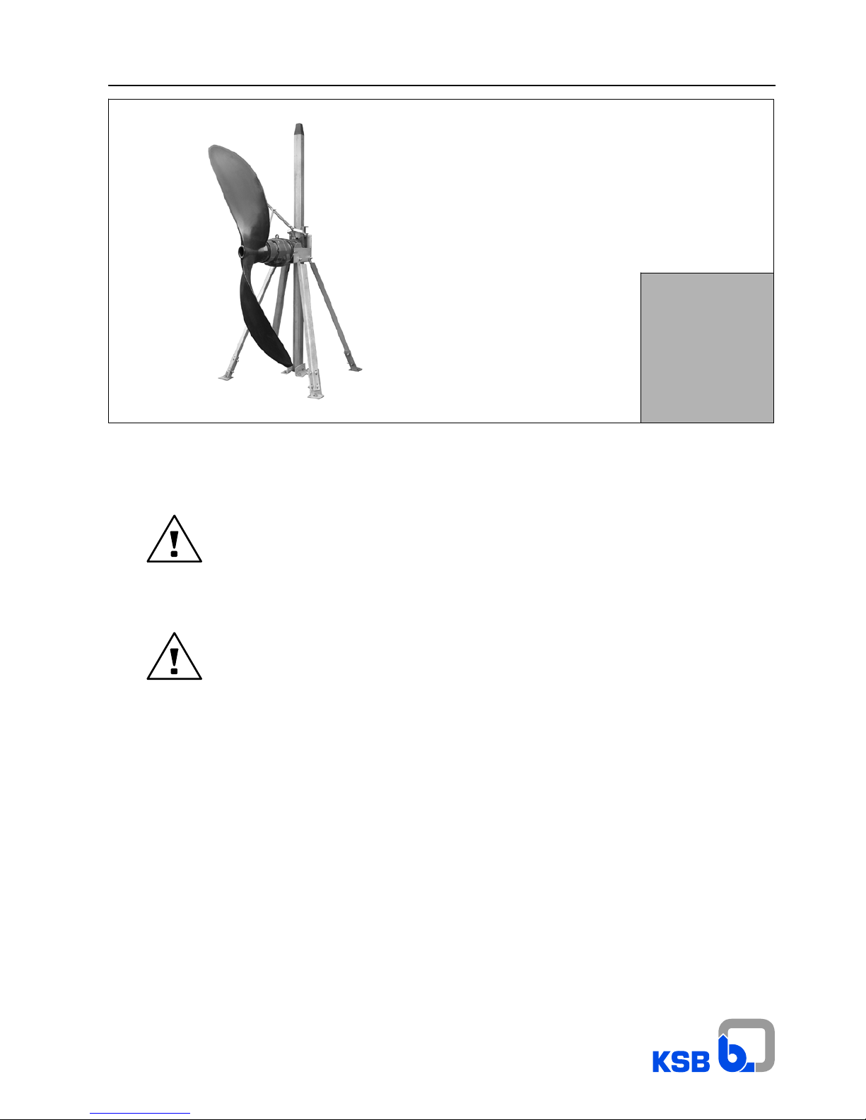
AmapropR
3
1 Preconditions for Installation
1.1 General
-- Safety
This operating manual contains fundamental instructions to be
observed in connection with installation, operation and
servicing. It is therefore imperative that this manual be read
prior to installation and commissioning by the fitter and the
technical personnel/operators concerned, and it must always
be kept available at or near the mixer.
Not only the general safety instructions contained in this
chapter must be complied with, but also all special safety
instructions included in other parts of this manual.
-- Marking of Instructions
All safety instructions included in this manual, the
non--observance of which could result in hazard to persons
involved, are preceded by the general hazard symbol, i. e.:
Safety sign in accordance with DIN 4844 -- W9,
Warnings about electrical hazards are preceded by the symbol:
Safety sign in accordance with DIN 4844 -- W8.
All safety instructions in this user’s manual, the
non--observance of which could jeopardise either the mixer
itself or its safe operation, are preceded by the word
Caution
-- Personnel Qualification and Training
All personnel involved in the operation, maintenance,
inspection or installation of the mixer must be duly qualified for
the work in question. The personnel’s responsibilities,
competence and supervision must be clearly defined by the
user. If the personnel in question are not already in possession
of the required skills and know--how, appropriate training and
instructions must be provided for. If required, the manufacturer/
supplier will provide such training at the user’s request. In
addition, the user is responsible for ensuring that the contents
of the operation manual are fully understood by the personnel
involved in the work.
-- Hazards Resulting from Non--compliance with the
Safety Instructions
Non--compliance with these safety instructions may jeopardise
the safety of people, property, the environment and the mixer
itself. Non--compliance with the safety instructions will also
lead to the forfeiture of any and all rights to claims for damages.
More specifically, non--compliance may, for example, result in:
-- failure of essential mixer and/or plant functions;
-- danger of injury caused by electrical shock, mechanical
impact or chemical exposure;
-- pollution of the environment due to leakage of hazardous
substances.
-- Safety Awareness
It is imperative to comply with the safety instructions contained
in this operation manual, the relevant national accident
prevention regulations and any of the user’s internal work,
operation and safety regulations.
-- Safety Instructions for the User/Operator
Take all necessary precautions to preclude electrical hazards
(for more information, consult the stipulations of the local power
supply companies).
-- Safety Instructions for Maintenance, Inspection and
Installation Work
The user is responsible for ensuring that all maintenance,
inspection and installation work is carried out by duly
authorised, adequately qualified, specialist personnel who are
thoroughly familiar with the contents of this operation manual.
As a general rule, work on the mixer must only be performed
during standstill. The shutdown procedure described in the
manual for taking the machine out of service must be strictly
adhered to.
Mixers used to handle hazardous substances have to be
decontaminated.
Immediately following completion of the work, all
safety--relevant and protective devices must be re--installed
and/or re--activated.
Please observe all instructions set out in the chapter headed
”Commissioning” before returning the machine to service.
(Mixer operating instructions, 1592.89).
-- Unauthorised Modification/Manufacture of Spare Parts
Modifications or alterations of the mixer, installation parts and
accessories supplied are only permitted with the
manufacturer’s prior approval.
The use of genuine spare parts and accessories approved by
the manufacturer helps ensure the operational safety and
reliability of the equipment. Please note that the use of other
than genuine parts and approved accessories can invalidate
the manufacturer’s liability for consequential damage.
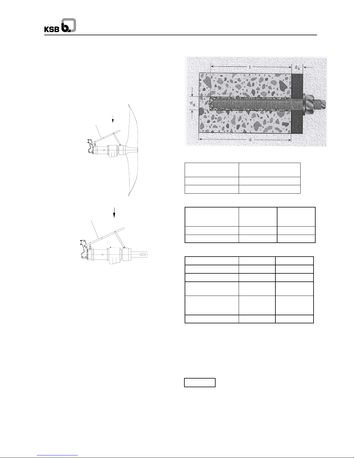
1.2 Checking the Site Prior to Installation
Check that the dimensions of the building are in agreement with
the dimension sheet. To ensure that the load--bearing capacity
of the foundation is sufficient for installation of the unit in
accordance with DIN 1045 or equivalent, the strength of the
concrete must at least correspond to category C20/25, as
specified in DIN 1045. Check that the concrete foundation has
fully set and hardened before proceeding with the installation
of the mixer.
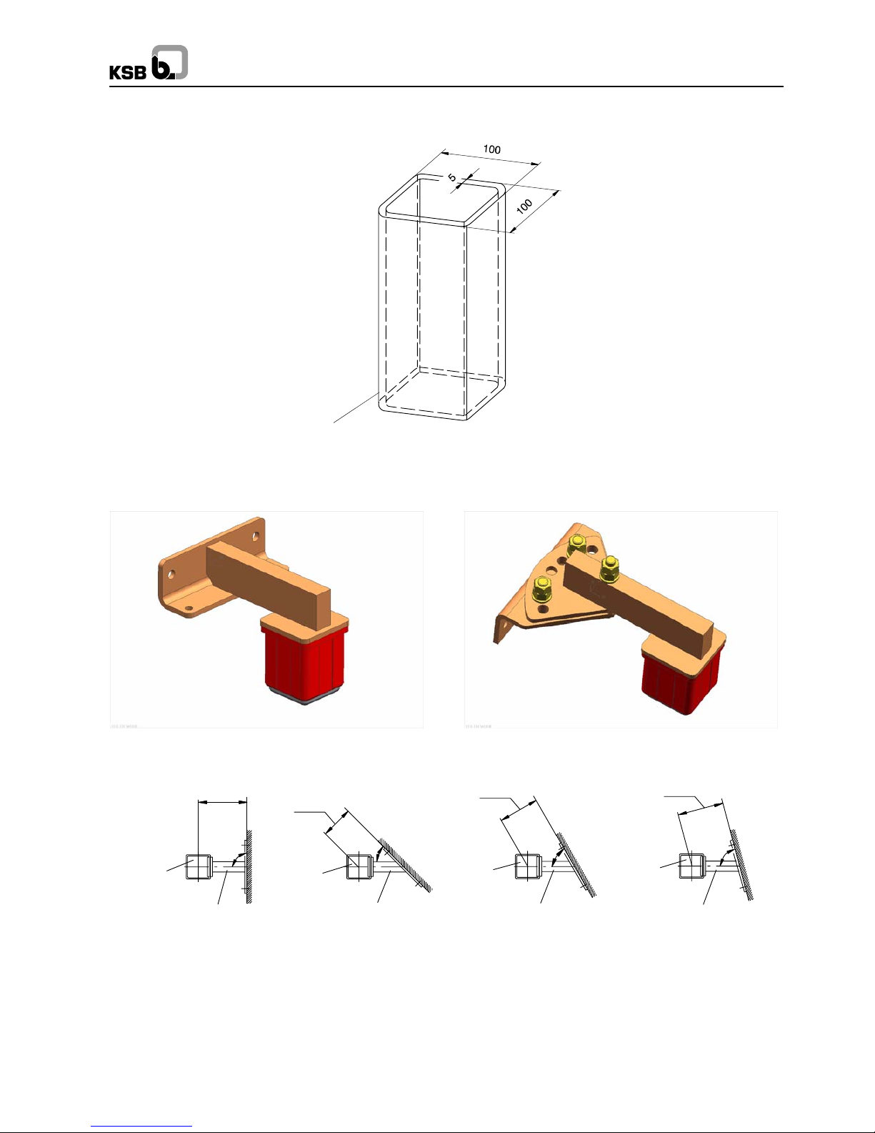
Even if the floor of the tank is inclined, the mounting area of the
mixer must be even. Otherwise, it would not be possible to
properly affix the installation hardware. The feet of the
installation parts must rest directly and fully on the concrete
surface, to ensure secure fastening by means of the composite
anchor bolts.