Amamix - direct
3
1 Pre-conditions for Installation
1.1 General
- Safety
This operating manual contains basic instructions, which must be
observed during installation, operation and servicing. Therefore
it is imperative that this manual is read prior to assembly by the
installer and relevant skilled staff/and operators, and it must
always be kept within the locality of the machine/plant.
Do not only observe the general safety notes under this section,
but as well any other notes regarding safety included in the
manual.
- Marking of Instructions
All safety instructions included in this manual are preceded by the
general hazard symbol, i.e.
The non-observance of this symbol may pose a health hazard to
those attending the site.
Warnings against electrical danger are preceded by this symbol:
The non-observance of this symbol may pose a health hazard to
those attending the site.
All safety instructions in this operation manual, the
non-observance of which may endanger the mixer itself or its
safe operation are preceded by the word
Attention
- Personnel Qualification and Training
All personnel involved in the operation, maintenance, inspection
or installation of the mixer must be qualified for the work in
question. The personnel’s responsibilities, competence and
supervision must be clearly defined by the user. To the extent that
the personnel in question is not already in possession of the
required skills and know - how, appropriate training and
instructions must be provided for. If required, the
manufacturer/supplier will provide such training at the user’s
request. In addition, the user is responsible for ensuring that the
contents of the operation manual are fully understood by the
personnel involved in the work.
- Dangers Resulting from Non - compliance with the
Safety Instructions
Non-compliance with the safety instructions may endanger the
safety of people, property, the environment and the mixer itself.
Non-compliance with the safety instructions will also lead to the
forfeiture of any and all rights to claims for damages.
More specifically, non-compliance may, for example, result in:
- Failure of essential mixer and/or plant functions;
- Health hazard due to electrical shock, mechanical impact,
chemical contamination.
- Pollution of the environment by the leakage of
hazardous substances.
- Safety Awareness
It is imperative to comply with the safety instructions contained in
this operation manual, the relevant national accident prevention
regulations and any of the user’s own work, operation and safety
regulations.
- Safety Instructions for the User / Operator
Take the necessary precautions to preclude all electrical hazards
(for more information, consult the stipulations of the local power
supply companies).
Safety Instructions for Maintenance, Inspection and
Installation Work
The user is responsible for ensuring that all maintenance,
inspection and installation work is carried out by duly authorized,
adequately qualified, specialist personnel who are thoroughly
familiar with the contents of this operation manual.
As a general rule, work on the mixer must only be performed
during standstill. The shutdown procedure described in the
manual for taking the machine out of service must be strictly
adhered to.
Mixers used to handle hazardous substances have to be
decontaminated.
Immediately following completion of the work, all safety-relevant
and protective devices must be re-installed and/or re- activated.
Please follow all instructions set out in the chapter entitled
“Commissioning” before returning the machine to service
(included in the mixer operating instructions, 1592.87.1-14).
- Unauthorized Modification and Manufacture of Spare
Parts
Neither the unit itself nor any installation hardware or accessory
may be modified or altered in any way without the prior consent
of the manufacturer.The use of genuine spare parts and
accessories approved by the manufacturer helps ensure the
operational safety and reliability of the equipment. Please note
that the use of other than genuine parts and approved
accessories can invalidate the manufacturer’s liability for
consequential damage.
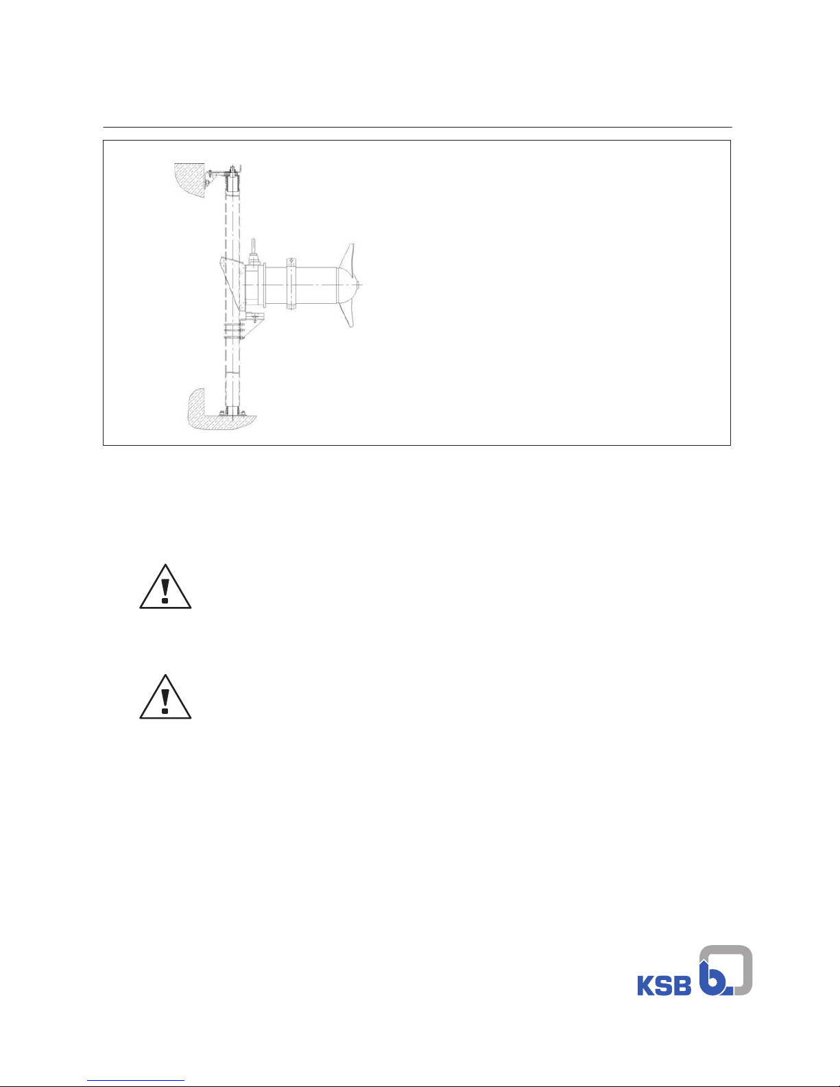
1.2 Checking the Site before Installation
Check that the building dimensions are in accordance with the
dimension sheet. To ensure that the carrying capacity of the
foundation is sufficient for installation of the unit, the strength of
the concrete must be at least 3,000 psi. Check that the concrete
foundation has set before proceeding with the installation of the
mixer.
Even if the reservoir floor is inclined, the surface must be leveled
if the installation parts are to be mounted to it securely.
1.3 Checking the Parts Before Installation
Before starting the installation, check that the installation parts
and accessories are complete and that they have not suffered any
transportation damage.