KSB Hya-Rain Installation instructions

Rainwater Harvesting System
Hya-Rain/Hya-Rain N
Installation/Operating Manual

Legal information/Copyright
Installation/Operating Manual Hya-Rain/Hya-Rain N
Original operating manual
All rights reserved. The contents provided herein must neither be distributed, copied, reproduced,
edited or processed for any other purpose, nor otherwise transmitted, published or made available to a
third party without the manufacturer's express written consent.
Subject to technical modification without prior notice.
© KSB SE & Co. KGaA, Frankenthal 21/01/2019

Contents
3 of 64
Hya-Rain/Hya-Rain N
Contents
Glossary .................................................................................................................................................. 5
1 General.................................................................................................................................................... 6
1.1 Principles ...........................................................................................................................................................6
1.2 Target group.....................................................................................................................................................6
1.3 Other applicable documents............................................................................................................................6
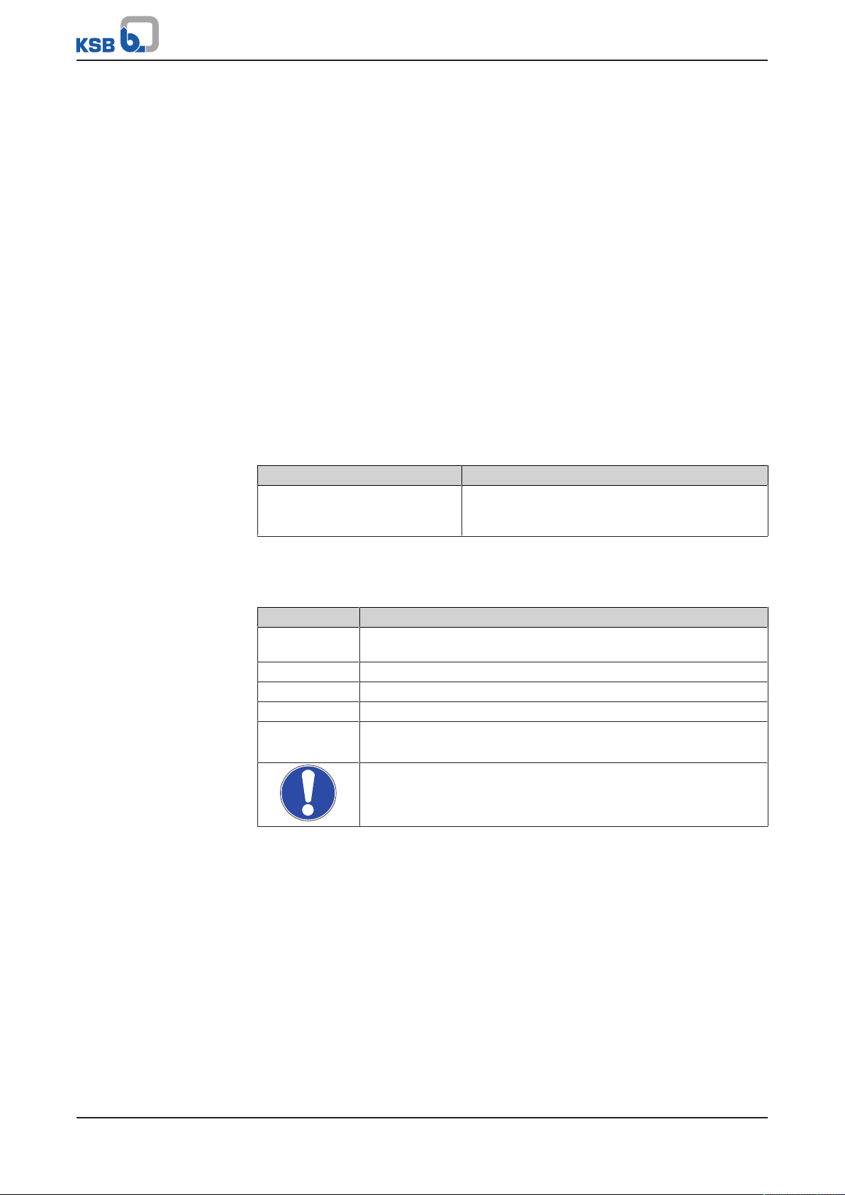
1.4 Symbols .............................................................................................................................................................6
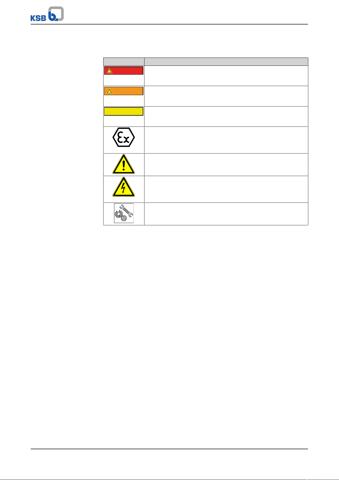
1.5 Key to safety symbols/markings.......................................................................................................................7
2 Safety...................................................................................................................................................... 8
2.1 General..............................................................................................................................................................8
2.2 Intended use .....................................................................................................................................................8
2.3 Personnel qualification and training...............................................................................................................9
2.4 Consequences and risks caused by non-compliance with these operating instructions ..............................9
2.5 Safety awareness ..............................................................................................................................................9
2.6 Safety information for the operator/user.......................................................................................................9
2.7 Safety information for maintenance, inspection and installation ................................................................9
2.8 Unauthorised modes of operation..................................................................................................................9
3 Transport/Temporary Storage/Disposal............................................................................................. 11
3.1 Checking the condition upon delivery..........................................................................................................11
3.2 Transport.........................................................................................................................................................11
3.3 Storage/preservation......................................................................................................................................12
3.4 Return to supplier...........................................................................................................................................12
3.5 Disposal ...........................................................................................................................................................13
4 Description............................................................................................................................................ 14
4.1 General description ........................................................................................................................................14
4.2 Designation.....................................................................................................................................................14
4.3 Name plate......................................................................................................................................................14
4.4 Design details..................................................................................................................................................15
4.5 Configuration and function...........................................................................................................................16
4.6 Noise characteristics .......................................................................................................................................17
4.7 Scope of supply...............................................................................................................................................17
4.8 Dimensions and weights ................................................................................................................................17
5 Installation at Site................................................................................................................................ 18
5.1 Safety regulations...........................................................................................................................................18
5.2 Checks to be carried out prior to installation...............................................................................................18
5.3 Setting up and installing the system.............................................................................................................18
5.4 Connecting the piping ...................................................................................................................................19
5.4.1 Connecting the mains water inlet ....................................................................................................19
5.4.2 Connecting the inlet line...................................................................................................................20
5.4.3 Connecting the discharge line ..........................................................................................................20
5.4.4 Connecting the overflow...................................................................................................................21
5.5 Electrical connection ......................................................................................................................................22
5.5.1 Connecting the float switch ..............................................................................................................22
5.5.2 Connecting the level control system.................................................................................................24
5.5.3 Connecting a booster pump (optional) ............................................................................................25
5.5.4 Connecting the system ......................................................................................................................27
6 Commissioning/Start-up/Shutdown................................................................................................... 28
6.1 Commissioning/Start-up.................................................................................................................................28
6.1.1 Prerequisites for commissioning/start-up .........................................................................................28
6.1.2 Priming and venting the system .......................................................................................................28
6.1.3 Start-up...............................................................................................................................................29
6.1.4 Functional test....................................................................................................................................29
6.2 Operating limits..............................................................................................................................................30

Contents
4 of 64 Hya-Rain/Hya-Rain N
6.2.1 Ambient conditions ...........................................................................................................................30
6.2.2 Maximum operating pressure ...........................................................................................................30
6.2.3 Fluid handled .....................................................................................................................................30
6.3 Shutdown/storage/preservation ....................................................................................................................31
6.3.1 Measures to be taken for shutdown ................................................................................................31
6.3.2 Stopping the system ..........................................................................................................................31
7 Operation.............................................................................................................................................. 32
7.1 Control panel..................................................................................................................................................32
7.2 Mode of operation.........................................................................................................................................33
7.2.1 Automatic mode ................................................................................................................................33
7.2.2 Mains water mode (manual mode) ..................................................................................................33
7.2.3 Rainwater mode (manual mode) ......................................................................................................33
7.2.4 Priming ...............................................................................................................................................34
7.3 Level control system (Hya-Rain N only).........................................................................................................35
7.3.1 Calibrating the level control system/ setting the rainwater storage tank design ........................36
7.3.2 Setting the switching level for the rainwater storage tank............................................................37
7.3.3 Setting and displaying the rainwater storage tank water replacement ........................................38
7.3.4 Setting the valve switchover .............................................................................................................39
8 Servicing/Maintenance........................................................................................................................ 40
8.1 General information/safety regulations........................................................................................................40
8.2 Maintenance/inspection.................................................................................................................................41
8.2.1 Replacing the stored mains water ...................................................................................................41
8.2.2 Checking the mains water mode ......................................................................................................41
8.2.3 Checking the pump control unit.......................................................................................................42
8.2.4 Checking the discharge lines.............................................................................................................42
8.3 Drainage/cleaning ..........................................................................................................................................42
8.4 Dismantling the system..................................................................................................................................42
8.4.1 Removing the pump set from the piping.........................................................................................42
8.4.2 Removing the pump control unit .....................................................................................................44
8.4.3 Removing the mechanical seal..........................................................................................................46
8.5 Reassembling the system ...............................................................................................................................47
8.5.1 Installing the mechanical seal ...........................................................................................................47
8.5.2 Installing the pump control unit.......................................................................................................48
8.5.3 Installing the pump set......................................................................................................................49
9 Trouble-shooting.................................................................................................................................. 51
10 Related Documents.............................................................................................................................. 53
10.1 General assembly drawing with list of components ....................................................................................53
10.2 Exploded view with list of components (pump)...........................................................................................54
10.3 Dimensions and connections .........................................................................................................................56
10.3.1 Hya-Rain / Hya-Rain N........................................................................................................................56
10.3.2 Connections........................................................................................................................................57
10.4 Drilling pattern for wall mounting ...............................................................................................................57
10.5 Wiring diagrams .............................................................................................................................................58
10.5.1 Hya-Rain .............................................................................................................................................58
10.5.2 Hya-Rain N..........................................................................................................................................59
11 EU Declaration of Conformity............................................................................................................. 61
12 Certificate of Decontamination........................................................................................................... 62
Index ..................................................................................................................................................... 63

Glossary
5 of 64
Hya-Rain/Hya-Rain N
Glossary
Certificate of decontamination
A certificate of decontamination is enclosed by the
customer when returning the product to the
manufacturer to certify that the product has been
properly drained to eliminate any environmental
and health hazards arising from components in
contact with the fluid handled.
Rainwater storage tank
Tank for collecting rainwater, for buried
installation or above-floor installation

1 General
6 of 64 Hya-Rain/Hya-Rain N
1 General
1.1 Principles
This operating manual is valid for the type series and variants indicated on the front
cover.
The operating manual describes the proper and safe use of this equipment in all
phases of operation.
The name plate indicates the type series, the main operating data and the serial
number. The serial number uniquely describes the product and is used as
identification in all further business processes.
In the event of damage, immediately contact your nearest KSB Service centre to
maintain the right to claim under warranty.
1.2 Target group
This operating manual is aimed at the target group of trained and qualified specialist
technical personnel. (ðSection2.3,Page9)
1.3 Other applicable documents
Table1: Overview of other applicable documents
Document Contents
Sub-supplier product literature Operating manuals, logic diagram and other
product literature of accessories and integrated
machinery components
1.4 Symbols
Table2: Symbols used in this manual
Symbol Description
✓Conditions which need to be fulfilled before proceeding with the
step-by-step instructions
⊳Safety instructions
⇨Result of an action
⇨Cross-references
1.
2.
Step-by-step instructions
Note
Recommendations and important information on how to handle
the product

1 General
7 of 64
Hya-Rain/Hya-Rain N
1.5 Key to safety symbols/markings
Table3: Definition of safety symbols/markings
Symbol Description
!DANGER
DANGER
This signal word indicates a high-risk hazard which, if not avoided,
will result in death or serious injury.
!WARNING
WARNING
This signal word indicates a medium-risk hazard which, if not
avoided, could result in death or serious injury.
CAUTION
CAUTION
This signal word indicates a hazard which, if not avoided, could
result in damage to the machine and its functions.
Explosion protection
This symbol identifies information about avoiding explosions in
potentially explosive atmospheres in accordance with EU Directive
2014/34/EU (ATEX).
General hazard
In conjunction with one of the signal words this symbol indicates a
hazard which will or could result in death or serious injury.
Electrical hazard
In conjunction with one of the signal words this symbol indicates a
hazard involving electrical voltage and identifies information about
protection against electrical voltage.
Machine damage
In conjunction with the signal word CAUTION this symbol indicates
a hazard for the machine and its functions.

2 Safety
8 of 64 Hya-Rain/Hya-Rain N
2 Safety
!DANGER
All the information contained in this section refers to hazardous situations.
In addition to the present general safety information the action-related safety
information given in the other sections must be observed.
2.1 General
▪This operating manual contains general installation, operating and maintenance
instructions that must be observed to ensure safe operation of the system and
prevent personal injury and damage to property.
▪Comply with all the safety instructions given in the individual sections of this
operating manual.
▪The operating manual must be read and understood by the responsible specialist
personnel/operators prior to installation and commissioning.
▪The contents of this operating manual must be available to the specialist
personnel at the site at all times.
▪Information and markings attached directly to the product must always be
complied with and kept in a perfectly legible condition at all times. This applies
to, for example:
– Arrow indicating the direction of rotation
– Markings for connections
– Type designation
▪The operator is responsible for ensuring compliance with all local regulations not
taken into account.
2.2 Intended use
▪The system must only be operated within the operating limits described in the
other applicable documents.
▪Only operate systems which are in perfect technical condition.
▪Do not operate partially assembled systems.
▪The system may only handle the fluids described in the product literature of the
relevant design variant.
▪Never operate the system without the fluid to be handled.
▪Observe the information on minimum flow rates specified in the product
literature (to prevent overheating, bearing damage, etc).
▪Observe the maximum flow rates indicated in the data sheet or product
literature (to prevent overheating, cavitation damage, bearing damage, etc).
▪Do not throttle the flow rate on the suction side of the system.
▪Consult the manufacturer about any other modes of operation not described in
the product literature.
Prevention of foreseeable misuse
▪Never exceed the permissible application and operating limits specified in the
product literature regarding pressure, temperature, etc.
▪Observe all safety information and instructions in this manual.

2 Safety
9 of 64
Hya-Rain/Hya-Rain N
2.3 Personnel qualification and training
All personnel involved must be fully qualified to install, operate, maintain and
inspect the equipment this manual refers to.
The responsibilities, competence and supervision of all personnel involved in
transport, installation, operation, maintenance and inspection must be clearly
defined by the operator.
Deficits in knowledge must be rectified by means of training and instruction
provided by sufficiently trained specialist personnel. If required, the operator can
commission the manufacturer/supplier to train the personnel.
Training at the system must always be supervised by the technical specialist
personnel.
2.4 Consequences and risks caused by non-compliance with these operating
instructions
▪Non-compliance with this operating manual will lead to forfeiture of warranty
cover and of any and all rights to claims for damages.
▪Non-compliance can, for example, have the following consequences:
– Hazard to persons by electrical, thermal and mechanical effects
– Failure of important product functions
– Failure of prescribed maintenance and servicing practices
2.5 Safety awareness
In addition to the safety information contained in this operating manual and the
intended use, the following safety regulations shall be complied with:
▪Accident prevention, health regulations and safety regulations
▪Safety regulations for handling hazardous substances
▪Applicable standards, directives and laws
2.6 Safety information for the operator/user
▪Eliminate all electrical hazards. (In this respect refer to the applicable national
safety regulations and/or regulations issued by the local energy supply
companies.)
2.7 Safety information for maintenance, inspection and installation
▪Modifications or alterations of the pump (set) are only permitted with the
manufacturer's prior consent.
▪Use only original spare parts or parts/components authorised by the
manufacturer. The use of other parts/components can invalidate any liability of
the manufacturer for resulting damage.
▪The operator ensures that maintenance, inspection and installation are
performed by authorised, qualified specialist personnel who are thoroughly
familiar with the manual.
▪Only carry out work on the system during standstill, with the system de-energised
and secured against unintentional start-up.
▪When taking the system out of service always adhere to the procedure described
in the manual.
▪As soon as the work has been completed, re-install and re-activate any safety-
relevant devices and protective devices. Before returning the product to service,
observe all instructions on commissioning. (ðSection6.1,Page28)
▪Make sure the system cannot be accessed by unauthorised persons (e.g. children).
2.8 Unauthorised modes of operation
Always observe the limits stated in the product literature.

2 Safety
10 of 64 Hya-Rain/Hya-Rain N
The warranty relating to the operating reliability and safety of the system supplied is
only valid if the system is used in accordance with its intended use.

3 Transport/Temporary Storage/Disposal
11 of 64
Hya-Rain/Hya-Rain N
3 Transport/Temporary Storage/Disposal
3.1 Checking the condition upon delivery
1. On transfer of goods, check each packaging unit for damage.
2. In the event of in-transit damage, assess the exact damage, document it and
notify KSB or the supplying dealer and the insurer about the damage in writing
immediately.
3.2 Transport
DANGER
System falling off the pallet
Risk of injury by falling system!
▷Always transport the system in a vertical position.
▷Never suspend the system by its power cable.
▷Use suitable, approved transport equipment, e.g. crane, forklift or pallet trucks.
NOTE
The system and accessories are shipped secured to a wooden pallet and covered
with a cardboard box. For transport two handles are provided on the side of the
cardboard box.
1. Cut the packing straps.
2. Carefully open the upper part of the cardboard box.
3. Take the accessories and padding out of the cardboard box.
4. Lift off the cardboard box.
ðThis exposes the system secured to the wooden pallet.
5. Check the packaging contents for completeness.
6. Check the system for any in-transit damage.
7. Select suitable transport equipment.
8. Transport the system to the place of installation.

3 Transport/Temporary Storage/Disposal
12 of 64 Hya-Rain/Hya-Rain N
3.3 Storage/preservation
CAUTION
Damage during storage by frost, humidity, dirt, UV radiation or vermin
Corrosion/contamination of the rainwater harvesting system!
▷Store the system in a frost-proof, roofed area.
CAUTION
Wet, contaminated or damaged openings and connections
Leakage or damage of the rainwater harvesting system!
▷Only open the openings of the rainwater harvesting system at the time of
installation.
If commissioning is to take place some time after delivery, we recommend that the
following measures be taken for storage:
▪Store the rainwater harvesting system in a dry, protected room with a constant
atmospheric humidity.
▪For storing a rainwater harvesting system which has already been operated,
observe the measures to be taken for shutdown. (ðSection6.3.1,Page31)
3.4 Return to supplier
1. Drain the system as per operating instructions.
2. Always flush and clean the system.
3. In addition, anhydrous inert gas must be blown through the system to ensure
drying.
4. Always complete and enclose a certificate of decontamination when returning
the system.
Always indicate any safety and decontamination measures taken.
NOTE
If required, a blank certificate of decontamination can be downloaded from the
following web site: www.ksb.com/certificate_of_decontamination

3 Transport/Temporary Storage/Disposal
13 of 64
Hya-Rain/Hya-Rain N
3.5 Disposal
WARNING
Fluids, consumables and supplies posing a health hazard
Hazard to persons and the environment!
▷Collect and dispose of any preservatives, flushing liquids and fluid residues.
▷Wear safety clothing and a protective mask, if required.
▷Observe all legal regulations on the disposal of fluids posing a health hazard.
1. Dismantle the product.
Collect greases and other lubricants during dismantling.
2. Separate and sort the materials, e.g. by:
- Metals
- Plastics
- Electronic waste
- Greases and other lubricants
3. Dispose of materials in accordance with local regulations or in another
controlled manner.
Electrical or electronic equipment marked with the adjacent symbol must not be
disposed of in household waste at the end of its service life.
Contact your local waste disposal partner for returns.
If the used electrical or electronic equipment contains personal data, the user is
responsible for deleting it before the equipment is returned.

4 Description
14 of 64 Hya-Rain/Hya-Rain N
4 Description
4.1 General description
▪Rainwater harvesting system
▪Handling clean to slightly contaminated water without aggressive, abrasive and
solid particles
4.2 Designation
Example: Hya-Rain N
Table4: Designation key
Code Description
Hya-Rain Type series
Hya-Rain With float switch
Hya-Rain N With fill level display and sensor
4.3 Name plate
1
2
4
38
7
9
10
Hya-Rain N
11037303
ZNI1448 P
230 V ~ 3,7 A
50 Hz 800 W IP 44
H
max
:43.0 m Q
max
:4,0 m³/h
2018w09
Made in Germany
Johann-Klein-Straße 9
Deutschland
67227 Frankenthal
KSB SE & Co. KGaA
6
5
26,5 kg
Hya-Rain N
Fig.1: Name plate (example)
1 Type series 6 Maximum head
2 Rated current 7 Serial number
3 Rated voltage 8 Total weight
4 Rated power 9 Enclosure
5 Frequency 10 Maximum flow rate
Table5: Key to the serial number
Code Description
2018 Calendar year
09 Calendar week

4 Description
15 of 64
Hya-Rain/Hya-Rain N
4.4 Design details
Design
▪Angled tank designed for wall mounting
▪Mains water storage tank to EN1717
– Material: PE-LLD, dark
– Storage volume approx. 13l
▪Float valve for mains water supply (approx. 2.7m³/h)
▪IP42 enclosure
Pump set
▪230V ± 10 %
▪DOL starting
▪Thermal class F
▪Enclosure IP44
▪Thermal motor protection with automatic reset and start-up
Bearings:
▪Grease-packed deep groove ball bearings sealed for life
Electrical connection
▪230V, 50Hz, 800W
▪Power input in stand-by mode: 2.5 - 3Watt
▪1.5m power cable with shockproof plug

4 Description
16 of 64 Hya-Rain/Hya-Rain N
4.5 Configuration and function
1
2
3
4
5
6
7
8
Fig.2: Sectional drawing
1 Pump control unit 5 Suction nozzle, rainwater storage
tank
2 Angled tank 6 Discharge outlet
3 High-pressure pump 7 Mains water supply
4 Thee-way valve 8 Suction nozzle, mains water storage
tank
Design A multi-stage self-priming high-pressure pump (3) is installed in an angled tank (2)
designed for wall mounting. Via a three-way valve (4) the high-pressure pump is
connected to a suction nozzle (5) leading out of the system for connection to a
rainwater storage tank.
Function The high-pressure pump (3) withdraws fluid handled from the rainwater storage tank
via the suction nozzle (5). A second suction nozzle (8) leads to an integrated mains
water storage tank, which contains approximately 13l of water. The water in the
mains water storage tank is automatically replenished with drinking water and/or
service water via a float valve. If the sensor fitted in the rainwater storage tank
indicates that the rainwater storage tank is empty, the system will automatically
switch to the mains water storage tank via a three-way valve (4). It will withdraw
water from the mains water storage tank until the rainwater storage tank contains a
sufficient amount of water again. Once the rainwater storage tank contains enough
water again, this condition is signalled to the system, which will then automatically
switch back to withdrawing water from the rainwater storage tank. The pump set is
started and stopped when a consumer installation is opened and closed.
Monitoring equipment For monitoring purposes and for protecting the pump against dry running, the
system is equipped with a pump control unit in the discharge line. When the pressure
falls below approx. 2.5bar (factory setting) the pump control unit starts up the pump
set. When the consumer installation is closed again, the pump control unit stops the
pump set after an after-run time of approx. 10seconds. A lift check valve prevents
the fluid handled from flowing back. The pressure is indicated by a fitted pressure
gauge.

4 Description
17 of 64
Hya-Rain/Hya-Rain N
4.6 Noise characteristics
Depending on the operating data of the system, the noise level will be approximately
49-50dB(A).
4.7 Scope of supply
▪Rainwater harvesting system
– Pump set
– Cervomatic ME control unit and monitoring unit
– Mains water storage tank to EN1717
– Terminals for connecting a booster pump
– Three-way valve with actuator, for automatic switching between rainwater
storage tank and mains water storage tank
– Set of mounting elements for wall mounting (bolts, plug fixings and
mounting brackets)
– Flexible expansion joints for the discharge side as well as for connection to
the mains water supply, length approx. 30/50cm
▪Bolt hole pattern
▪Installation/operating manual
Hya-Rain:
▪Float switch, cable length 20m
Hya-Rain N:
▪Sensor, cable length 3m, including connection box
4.8 Dimensions and weights
For dimensions refer to the outline drawings. (ðSection10.3.1,Page56)
Table6: Weights
Type series Weight
Without water fill With water fill
[kg] [kg]
Hya-Rain Approx. 26 Approx. 42
Hya-Rain N Approx. 27 Approx. 43

5 Installation at Site
18 of 64 Hya-Rain/Hya-Rain N
5 Installation at Site
5.1 Safety regulations
DANGER
Unsuitable electrical installation
Danger to life!
▷Make sure the electrical installation meets the VDE 0100 installation rules (i.e.
sockets with earthing terminals).
▷Make sure the electric mains is equipped with a residual current device of
maximum 30 mA.
▷Always have the electrical connections installed by a trained and qualified
electrician.
5.2 Checks to be carried out prior to installation
Before beginning with the installation check the following:
▪The system can be operated on the power supply network according to the data
on the name plate. (ðSection4.3,Page14)
▪The fluid to be handled matches the description of suitable fluids.
(ðSection6.2.3.1,Page30)
▪The installation room is dry, frost-free and well-ventilated.
▪The ambient conditions have been met. (ðSection6.2.1,Page30)
▪The wall (e.g. outside wall) is suitable for accommodating 4plug fixings of
10mm diameter and for carrying the weight of the system.
(ðSection4.8,Page17)
5.3 Setting up and installing the system
üA suitable installation site has been selected that meets the requirements.
üSufficient clearance in all directions is provided for servicing work.
1. Fasten the bolt hole pattern provided to the corresponding wall.
(ðSection10.4,Page57)
2. Drill four holes of 10mm diameter in accordance with the bolt hole pattern.
3. Insert the plug fixings.
4. Mount and align the lower hanging brackets.
5. Undo the nuts. Remove the cover.
6. Place the system on the lower hanging brackets.
7. Fit the upper hanging brackets.
8. Fit the system cover. Fasten it with nuts.

5 Installation at Site
19 of 64
Hya-Rain/Hya-Rain N
5.4 Connecting the piping
5.4.1 Connecting the mains water inlet
CAUTION
Excessive bend of connection line
System defect due to impermissible loads on the system!
Reduced service life!
▷Connect the connection line without transmitting any stresses or strains.
No forces must act on the connection nozzles and the system.
CAUTION
Pressure higher than mains water back-up limit of 4 bar
System defect due to impermissible load!
▷Install pressure reducers upstream of the system to make sure that the inlet
pressure of the mains water supply does not exceed 4 bar.
CAUTION
Solid substances in the drinking water (stones, sediments, limescale deposits)
System defect due to impermissible loads!
Reduced service life!
▷If used in areas where the drinking water quality is affected by the above,
provide a drinking water filter.
NOTE
Fitting a shut-off valve at the site is recommended.
741.02
Fig.3: Connecting the mains water inlet
1. Connect the mains water inlet to the mains water supply (float valve 741.02)
R 3/4.
2. Open the mains water supply line.
ðThe mains water storage tank will fill automatically once the mains water
supply line is opened.

5 Installation at Site
20 of 64 Hya-Rain/Hya-Rain N
5.4.2 Connecting the inlet line
NOTE
The suction-side inlet line (suction hose or suction pipe) must be tightly sealed to
enable self-priming of the pump set.
Fig.4: Connecting the inlet line
üThe inlet line (suction hose or suction pipe) has a diameter of at least 1inch.
1. Lay the inlet line coming from the rainwater storage tank with a continuously
rising slope towards the pump set.
2. Screw the inlet line to the suction nozzle at the bottom of the rainwater
harvesting system.
3. Fit a lift check valve at the rainwater storage tank end of the suction line.
5.4.3 Connecting the discharge line
CAUTION
Excessive bend of connection line
System defect due to impermissible loads on the system!
Reduced service life!
▷Connect the connection line without transmitting any stresses or strains.
No forces must act on the connection nozzles and the system.
NOTE
Fitting a shut-off valve at the site is recommended.
1. Connect hose 719.02, leading it out at the right or left of the rainwater piping
system. Prevent excessive bending of the flexible connection lines.
Other manuals for Hya-Rain
1
This manual suits for next models
1
Table of contents
Other KSB Water System manuals
Popular Water System manuals by other brands

Pentair
Pentair Raychem HWAT System Installation and operation manual

Everpure
Everpure SSFM-100BC-SYS Specification sheet

Webasto
Webasto BLUE COOL Operation manual

Carel
Carel Compact ROC 25 user manual

Zepter
Zepter AqueenaPro WT-100 Installation and repair manual

Everpure
Everpure Single Head 41QC7I Specification sheet

Lubing
Lubing LC-2 Assembly instructions and operator's manual

Cattron
Cattron Aquavx user manual

Elkay
Elkay HATENBOER WATER VRCGNDWS C Series Installation and use manual

Medora
Medora SolarBee SB10000DM owner's manual

Hellenbrand
Hellenbrand Iron curtain System 2.0 owner's manual

blupura
blupura TOP CONTROL manual