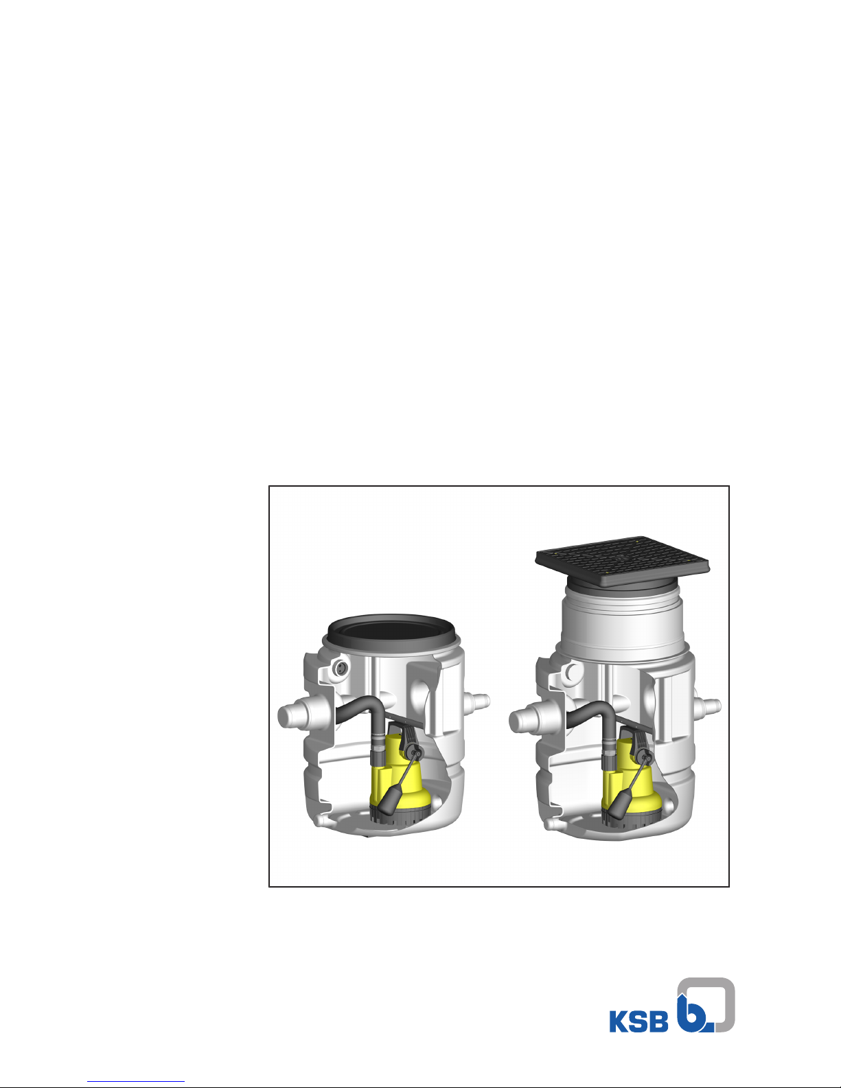
KSB Ama-Drainer-Box User manual

Automatic Waste Water Lifting Unit
Ama-Drainer-Box
Installation/Operating Manual

Legal information/Copyright
Installation/Operating Manual Ama-Drainer-Box
Original operating manual
All rights reserved. The contents provided herein must neither be distributed, copied, reproduced,
edited or processed for any other purpose, nor otherwise transmitted, published or made available to a
third party without the manufacturer's express written consent.
Subject to technical modification without prior notice.
© KSB SE & Co. KGaA, Frankenthal 08/01/2018

Contents
3 of 72
Ama-Drainer-Box
Contents
Glossary .................................................................................................................................................. 5
1 General.................................................................................................................................................... 6
1.1 Principles ...........................................................................................................................................................6
1.2 Installation of partly completed machinery....................................................................................................6
1.3 Target group.....................................................................................................................................................6
1.4 Other applicable documents............................................................................................................................6
1.5 Symbols .............................................................................................................................................................6
2 Safety...................................................................................................................................................... 7
2.1 Key to safety symbols/markings.......................................................................................................................7
2.2 General..............................................................................................................................................................7
2.3 Personnel qualification and training...............................................................................................................7
2.4 Consequences and risks caused by non-compliance with this manual .........................................................8
2.5 Safety awareness ..............................................................................................................................................8
2.6 Safety instructions for the operator/user........................................................................................................8
2.7 Safety information for maintenance, inspection and installation ................................................................8
2.8 Unauthorised modes of operation..................................................................................................................8
2.9 Intended use .....................................................................................................................................................9
3 Transport/Temporary Storage/Disposal............................................................................................. 10
3.1 Checking the condition upon delivery..........................................................................................................10
3.2 Transport.........................................................................................................................................................10
3.3 Storage/preservation......................................................................................................................................10
3.4 Return to supplier...........................................................................................................................................10
3.5 Disposal ...........................................................................................................................................................11
4 Description............................................................................................................................................ 12
4.1 General description ........................................................................................................................................12
4.2 Designation.....................................................................................................................................................12
4.3 Name plate......................................................................................................................................................12
4.4 Design details..................................................................................................................................................12
4.5 Configuration and function...........................................................................................................................13
4.6 Fluids handled.................................................................................................................................................14
4.7 Scope of supply...............................................................................................................................................14
4.8 Dimensions and weights ................................................................................................................................16
5 Installation at Site................................................................................................................................ 17
5.1 Safety regulations...........................................................................................................................................17
5.2 Checks to be carried out prior to installation...............................................................................................17
5.3 Installing the lifting unit................................................................................................................................18
5.3.1 Installing the underfloor box ............................................................................................................18
5.3.2 Connect the underfloor box piping..................................................................................................19
5.3.3 Fitting the level-adjusting piece or the puddle flange with level-adjusting piece (not included in
the scope of supply)...........................................................................................................................24
5.3.4 Fitting MK400 and MK630 puddle flanges (not included in the scope of supply) ......................24
5.3.5 Backfilling around the tank ..............................................................................................................25
5.3.6 Fitting the sealing collar....................................................................................................................27
5.4 Installing the above-floor lifting unit ...........................................................................................................29
5.4.1 Installing the above-floor box...........................................................................................................29
5.4.2 Connecting the above-floor box piping ...........................................................................................30
5.5 Installing the submersible motor pump(s)....................................................................................................33
5.5.1 Single-pump units ..............................................................................................................................33
5.5.2 Dual-pump units ................................................................................................................................39
5.6 Fitting the cover plate/cover..........................................................................................................................43
5.7 Venting device with activated carbon filter (accessories)............................................................................45
6 Commissioning/Start-up/Shutdown................................................................................................... 47
6.1 Commissioning/Start-up.................................................................................................................................47

Contents
4 of 72 Ama-Drainer-Box
6.1.1 Prerequisites for commissioning/start-up .........................................................................................47
6.1.2 Starting up/stopping the pump set...................................................................................................47
6.1.3 Operating limits .................................................................................................................................47
6.2 Shutdown/storage/preservation ....................................................................................................................47
6.2.1 Measures to be taken for shutdown ................................................................................................47
6.3 Returning to service .......................................................................................................................................48
7 Servicing/Maintenance........................................................................................................................ 49
7.1 Safety regulations...........................................................................................................................................49
7.2 Servicing/inspection........................................................................................................................................49
7.3 Drainage/cleaning ..........................................................................................................................................50
7.4 Recommended spare parts stock...................................................................................................................50
8 Trouble-shooting.................................................................................................................................. 51
9 Related Documents.............................................................................................................................. 52
9.1 General assembly drawing with list of components ....................................................................................52
9.1.1 Single-pump unit underfloor box1U / above-floor box1B...........................................................52
9.1.2 Dual-pump unit underfloor boxZ2U / above-floor boxZ2B .........................................................55
9.2 Dimensions......................................................................................................................................................58
9.2.1 Underfloor box of single-pump unit 1 U..........................................................................................58
9.2.2 Above-floor box of single-pump unit 1 B.........................................................................................59
9.2.3 Underfloor box of dual-pump unit Z2 U ..........................................................................................60
9.2.4 Above-floor box of dual-pump unit Z2 B .........................................................................................61
9.3 Installation example.......................................................................................................................................62
9.3.1 Underfloor box 1 U ............................................................................................................................62
9.3.2 Above-floor box 1 B...........................................................................................................................62
9.3.3 Underfloor box Z2 U ..........................................................................................................................63
9.3.4 Above-floor box Z2 B.........................................................................................................................63
10 EU Declaration of Conformity............................................................................................................. 65
11 Declaration of Performance as per Regulation (EU) No. 305/2011, Annex III.................................. 66
12 Certificate of Decontamination........................................................................................................... 67
Index ..................................................................................................................................................... 68

Glossary
5 of 72
Ama-Drainer-Box
Glossary
Backflow loop
The section of the discharge pipe of a waste water
lifting unit that is located above the flood level
Certificate of decontamination
A certificate of decontamination is enclosed by the
customer when returning the product to the
manufacturer to certify that the product has been
properly drained to eliminate any environmental
and health hazards arising from components in
contact with the fluid handled.
Check valve
Element of a waste water lifting unit which
prevents waste water from flowing back from the
discharge line into the lifting unit.
Collecting tank
Component of a waste water lifting unit in which
the incoming waste water is stored in
unpressurised condition prior to automatic lifting.
Domestic waste water
Faecal-free waste water (grey water) from
washbasins, showers, washing machines, etc.
EN 12050-2
European Standard for waste water lifting units
which are used to dispose of faeces-free waste
water occurring below the flood level of buildings
and sites. It defines general requirements as well
as principles of construction and testing.
Grey water
Faecal-free waste water from washbasins,
showers, washing machines, etc.
Inlet line
Pipe used for draining waste water from sanitary
installations into the lifting unit
Noise characteristics
The noise characteristics are indicated as surface
sound pressure level in dB(A).
Nominal diameter DN
Identifier (inside diameter) used for characterising
mating components such as pipes, pipe
connections and fittings
Stormwater
Water from natural precipitation which has not
been contaminated by any form of use
Submersible motor pump
Submersible motor pumps are floodable, close-
coupled units which are not self-priming. The
pumps are usually operated completely
submerged. They may be operated outside the
fluid for short periods of time, until the minimum
fluid level has been reached.
Waste water
Water which has been changed by some type of
use, e.g. domestic waste water
Waste water lifting unit
Device for collecting and automatically lifting
faecal-free waste water above the flood level

1 General
6 of 72 Ama-Drainer-Box
1 General
1.1 Principles
This operating manual is supplied as an integral part of the type series and variants
indicated on the front cover. The manual describes the proper and safe use of this
equipment in all phases of operation.
The name plate indicates the type series, the main operating data and the serial
number. The serial number uniquely describes the product and is used as
identification in all further business processes.
In the event of damage, immediately contact your nearest KSB service centre to
maintain the right to claim under warranty.
Observe the noise characteristics, indicated as surface sound pressure level.
1.2 Installation of partly completed machinery
To install partly completed machinery supplied by KSB refer to the sub-sections under
Servicing/Maintenance.
1.3 Target group
This operating manual is aimed at the target group of trained and qualified specialist
technical personnel.
1.4 Other applicable documents
Table1: Overview of other applicable documents
Document Contents
Sub-supplier product literature Operating manuals and other product literature
of accessories and integrated machinery
components
Operating manual of submersible motor pump
Operating manual of control unit for dual-pump
units
1.5 Symbols
Table2: Symbols used in this manual
Symbol Description
✓Conditions which need to be fulfilled before proceeding with the
step-by-step instructions
⊳Safety instructions
⇨Result of an action
⇨Cross-references
1.
2.
Step-by-step instructions
Note
Recommendations and important information on how to handle
the product

2 Safety
7 of 72
Ama-Drainer-Box
2 Safety
!DANGER
All the information contained in this section refers to hazardous situations.
2.1 Key to safety symbols/markings
Table3: Definition of safety symbols/markings
Symbol Description
!DANGER
DANGER
This signal word indicates a high-risk hazard which, if not avoided,
will result in death or serious injury.
!WARNING
WARNING
This signal word indicates a medium-risk hazard which, if not
avoided, could result in death or serious injury.
CAUTION
CAUTION
This signal word indicates a hazard which, if not avoided, could
result in damage to the machine and its functions.
General hazard
In conjunction with one of the signal words this symbol indicates a
hazard which will or could result in death or serious injury.
Electrical hazard
In conjunction with one of the signal words this symbol indicates a
hazard involving electrical voltage and identifies information about
protection against electrical voltage.
Machine damage
In conjunction with the signal word CAUTION this symbol indicates
a hazard for the machine and its functions.
2.2 General
This operating manual contains general installation, operating and maintenance
instructions that must be observed to ensure safe operation of the system and
prevent personal injury and damage to property.
The safety information in all sections of this manual must be complied with.
The operating manual must be read and understood by the responsible specialist
personnel/operators prior to installation and commissioning.
The contents of this operating manual must be available to the specialist personnel
at the site at all times.
Information attached directly to the product must always be complied with and kept
in a perfectly legible condition at all times. This applies to, for example:
▪Arrow indicating the direction of rotation
▪Markings for connections
▪Name plate
The operator is responsible for ensuring compliance with all local regulations not
taken into account in this operating manual.
2.3 Personnel qualification and training
All personnel involved must be fully qualified to install, operate, maintain and
inspect the equipment this manual refers to.
The responsibilities, competence and supervision of all personnel involved in
installation, operation, maintenance and inspection must be clearly defined by the
operator.
Deficits in knowledge must be rectified by means of training and instruction
provided by sufficiently trained specialist personnel. If required, the operator can
commission the manufacturer/supplier to train the personnel.
Training on the lifting unit must always be supervised by technical specialist
personnel.

2 Safety
8 of 72 Ama-Drainer-Box
2.4 Consequences and risks caused by non-compliance with this manual
▪Non-compliance with this operating manual will lead to forfeiture of warranty
cover and of any and all rights to claims for damages.
▪Non-compliance can, for example, have the following consequences:
–Hazards to persons due to electrical, thermal, mechanical and chemical
effects and explosions
–Failure of important product functions
–Failure of prescribed maintenance and servicing practices
–Hazard to the environment due to leakage of hazardous substances
2.5 Safety awareness
In addition to the safety information contained in this manual and the intended use,
the following safety regulations shall be complied with:
▪Accident prevention, health and safety regulations
▪Explosion protection regulations
▪Safety regulations for handling hazardous substances
▪Applicable standards, directives and laws
2.6 Safety instructions for the operator/user
▪The operator shall fit contact guards for hot, cold and moving parts and check
that the guards function properly.
▪Do not remove any contact guards during operation.
▪Provide the personnel with protective equipment and make sure it is used.
▪Contain leakages (e.g. at the shaft seal) of hazardous fluids handled (e.g.
explosive, toxic, hot) so as to avoid any danger to persons and the environment.
Adhere to all relevant laws.
▪Eliminate all electrical hazards. (In this respect refer to the applicable national
safety regulations and/or regulations issued by the local energy supply
companies.)
2.7 Safety information for maintenance, inspection and installation
▪Modifications or alterations of the lifting unit require the manufacturer's prior
consent.
▪Use only original spare parts or parts authorised by the manufacturer. The use of
other parts can invalidate any liability of the manufacturer for resulting damage.
▪The operator ensures that maintenance, inspection and installation is performed
by authorised, qualified specialist personnel who are thoroughly familiar with
the manual.
▪Carry out work on the lifting unit during standstill only.
▪The pump casing must have cooled down to ambient temperature.
▪Pump pressure must have been released and the pump must have been drained.
▪When taking the lifting unit out of service always adhere to the procedure
described in the manual.
▪Decontaminate lifting units which handle fluids posing a health hazard.
▪As soon as the work has been completed, re-install and re-activate any safety-
relevant devices and protective devices. Before returning the product to service,
observe all instructions on commissioning.
▪Make sure the lifting unit cannot be accessed by unauthorised persons (e.g.
children).
2.8 Unauthorised modes of operation
Always observe the limits stated in the product literature.

2 Safety
9 of 72
Ama-Drainer-Box
The warranty relating to the operating reliability and safety of the lifting unit
supplied is only valid if the equipment is used in accordance with its intended use.
(ðSection2.9,Page9)
2.9 Intended use
▪The lifting unit must not be used in potentially explosive atmospheres.
▪The lifting unit must only be operated within the operating limits described in
the other applicable documents.
▪Only operate lifting units which are in perfect technical condition.
▪Do not operate partially assembled lifting units.
▪Only use the lifting unit to handle the fluids described in the product literature
of the respective design variant.
▪Never operate the lifting unit without the fluid to be handled
▪Observe the minimum flow rates indicated in the data sheet or product literature
(to prevent overheating, bearing damage, etc).
▪Observe the maximum flow rates indicated in the data sheet or product
literature (to prevent overheating, mechanical seal damage, cavitation damage,
bearing damage, etc).
▪Do not throttle the flow rate on the inlet side of the lifting unit (to prevent
cavitation damage)
▪Consult the manufacturer about any use or mode of operation not described in
the data sheet or product literature.
▪Never exceed the permissible operating limits specified in the data sheet or
product literature regarding pressure, temperature, etc.
▪Observe all safety information and instructions in this manual.

3 Transport/Temporary Storage/Disposal
10 of 72 Ama-Drainer-Box
3 Transport/Temporary Storage/Disposal
3.1 Checking the condition upon delivery
1. On transfer of goods, check each packaging unit for damage.
2. In the event of in-transit damage, assess the exact damage, document it and
notify KSB or the supplying dealer and the insurer about the damage in writing
immediately.
3.2 Transport
DANGER
Waste water lifting unit falling off the pallet
Risk of injury by falling waste water lifting unit!
▷Always transport the waste water lifting unit in horizontal position.
▷Give due attention to the weight data and the centre of gravity.
▷Never suspend the pump by its power cable.
▷Prevent the waste water lifting unit from getting knocked or dropped.
3.3 Storage/preservation
If commissioning is to take place some time after delivery, we recommend that the
following measures be taken for storage.
CAUTION
Damage during storage due to frost, humidity, dirt, UV radiation or vermin
Corrosion/contamination of the lifting unit!
▷Store the lifting unit in a frost-proof, roofed area.
CAUTION
Wet, contaminated or damaged openings and connections
Leakage of or damage to the lifting unit!
▷Only remove caps/covers from the openings of the lifting unit at the time of
installation.
Store the lifting unit in a dry, protected room where the atmospheric humidity is as
constant as possible.
3.4 Return to supplier
1. Drain the lifting unit as described in the manual.
2. Always flush and clean the lifting unit, particularly if it has been used for
handling noxious, explosive, hot or other hazardous fluids.
3. If the unit has handled fluids whose residues could lead to corrosion damage in
the presence of atmospheric humidity or could ignite upon contact with oxygen,
the unit must also be neutralised and blown through with anhydrous inert gas
to ensure drying.
4. Always complete and enclose a certificate of decontamination when returning
the lifting unit. (ðSection12,Page67)
Always indicate any safety and decontamination measures taken.
NOTE
If required, a blank certificate of decontamination can be downloaded from the
following web site: www.ksb.com/certificate_of_decontamination

3 Transport/Temporary Storage/Disposal
11 of 72
Ama-Drainer-Box
3.5 Disposal
WARNING
Fluids, consumables and supplies which are hot and/or pose a health hazard
Hazard to persons and the environment!
▷Collect and properly dispose of flushing fluid and any residues of the fluid
handled.
▷Wear safety clothing and a protective mask if required.
▷Observe all legal regulations on the disposal of fluids posing a health hazard.
1. Dismantle the lifting unit.
Collect greases and other lubricants during dismantling.
2. Separate and sort the pump materials, e.g. by:
- Metals
- Plastics
- Electronic waste
- Greases and other lubricants
3. Dispose of materials in accordance with local regulations or in another
controlled manner.

4 Description
12 of 72 Ama-Drainer-Box
4 Description
4.1 General description
▪Automatic waste water lifting unit
Lifting unit for the collection and automatic lifting of unpressurised, domestic waste
water without faeces as well as rainwater above the flood level.
4.2 Designation
Example: Ama-Drainer-Box Z2 U 301
Table4: Designation key
Code Description
Ama-Drainer-Box Type series
Z Dual-pump unit
No code = single-pump unit
2 200 litres total collecting tank volume
1 = 100 litres
U Underfloor installation
B = above-floor installation
301 Pump code number
e.g. 301 = Ama-Drainer N 301
4.3 Name plate
2
1
3
4
5
EN 12 050-2
0197 11
DoP2336.1-01
FO001999 Made in Germany
2016w20
Ama-Drainer-Box Z2 B
Johann-Klein-Straße 9
Deutschland
67227 Frankenthal
KSB SE & Co. KGaA
Fig.1: Name plate (example)
1 Type series, size 2 Principles of construction and
testing
3 Notified body / year of introduction 4 Reference number of the
declaration of performance
5 Year/week of construction
Table5: Key to the serial number
Calendar year Calendar week
2016 w16
4.4 Design details
Design
Underfloor Box U:
▪Collecting tank made of impact-resistant plastic, 100litres, for installation in
substructures and foundations. Cover with level-adjusting extension, cover plate
with floor drain and siphon trap.
▪Single-pump or dual-pump units
▪Tank volume 100 litres or 200 litres
▪To EN 12050-2

4 Description
13 of 72
Ama-Drainer-Box
Above-floor Box B:
▪Collecting tank made of impact-resistant plastic, 100litres, for floor mounting;
closed with odour-proof, screw-on cover and locking ring.
▪Single-pump or dual-pump units
▪Tank volume 100 litres or 200 litres
▪To EN 12050-2
Installation
▪Stationary installation
Connections
Single-pump units Box 1 U and Box 1 B:
▪Inlet side: DN 50 / DN 70 / DN 100
▪Discharge outlet: DN 40 / G 1 1/2
Dual-pump units Box Z2U and Box Z2B:
▪Inlet side: DN 50 / DN 70 / DN 100 / DN 150
▪Discharge outlet: DN 50 / G 2
Drive
▪Single-phase AC motor
▪Three-phase motor
▪Integrated temperature switch
Impeller type
▪Open multi-vane impeller, free passage of 10/11mm
▪Free-flow impeller, free passage of 35 mm
4.5 Configuration and function
1
1
2
3
4
5
Fig.2: Sectional drawing
1 Collecting tank 2 Inlet-side connection
3 Float switch 4 Discharge-side connection
5Submersible motor pump
Design The lifting unit consists of a stable collecting tank (1) with integrated submersible
motor pump (5), an inlet-side connection (2) and a discharge-side connection (4).
Function The fluid to be handled flows into the lifting unit through the inlet-side connection
(2) and is collected in an odour-tight and water-tight plastic tank (1). When a
specified fluid level is reached, the float switch (3) triggers the automatic start of the
submersible motor pump (5). The fluid handled is then pumped through the
discharge-side connection (4) to a level above the flood level and discharged into the
public sewer.

4 Description
14 of 72 Ama-Drainer-Box
4.6 Fluids handled
WARNING
Pumping of impermissible fluids
Hazardous to persons and the environment!
▷Only discharge permissible fluids into the public sewer system.
▷Check the suitability of pump/system materials.
CAUTION
Unsuitable fluids
Damage to the pump!
▷Never use the pump to handle corrosive, combustible or explosive fluids.
▷Never use the pump to transport waste water from toilets and urinal systems.
▷Do not use the pump for foodstuff applications.
Standard variant
Suitable for handling chemically neutral, slightly contaminated waste water as well as
wash water.
Variant C for aggressive water
Suitable for handling the above fluids and, in addition:
▪Seawater and water containing salt
▪Swimming pool water and brackish water
▪Aggressive waste water
Variant R for water containing oil and oil emulsions
Suitable for handling the above fluids and, in addition:
▪Oil emulsions and cutting oils
▪Waste water containing oil
4.7 Scope of supply
The off-the-shelf range contains the complete ready-to-connect waste water lifting
unit as one material number. In the configurable range, the waste water lifting unit
is composed of individually selected components. Lifting units from both the off-the-
shelf and the configurable range are supplied in several parts for assembly on site.
Ama-Drainer-Box waste water lifting units meet the requirements of EN12050-2.
Underfloor Box 1U – single-pump unit
▪Collecting tank made of impact-resistant plastic, 100litres, for installation in
substructures and foundations. Cover with level-adjusting extension, cover plate
with floor drain and siphon trap.
Supplied in three parts:
▪Collecting tank with extension and cover plate Class K3.
▪Submersible waste water pump that starts and stops automatically, with 5m or
10m power cable (depending on pump size) and shockproof plug or CEE plug
(for models with three-phase motor).
▪Connection set with full set of installation parts and swing check valve1)
1) A swing check valve is integrated for Ama-DrainerN301, N302 and N303.

4 Description
15 of 72
Ama-Drainer-Box
Underfloor Box Z2U – dual-pump unit
▪Collecting tank made of impact-resistant plastic, for installation in substructures
and foundations. Cover with level-adjusting extension, cover plate with floor
drain and siphon trap.
Supplied in four parts:
▪Collecting tank with extension and cover plate Class K3.
▪Two submersible waste water pumps with 10m power cable and shockproof
plug, or free cable end for models with three-phase motor.
▪Connection set with full set of installation parts, swing check valve2) and two
float switches, with 10m cable
▪LevelControl Basic2 control unit for dual-pump units with automatic alternate,
peak-load and stand-by operation function.
Above-floor Box 1B – single-pump unit
▪Collecting tank made of impact-resistant plastic, 100litres, for floor mounting;
closed with odour-proof, screw-on cover and locking ring.
Supplied in three parts:
▪Collecting tank with cover and locking ring
▪Submersible waste water pump that starts and stops automatically, with 5m or
10m power cable (depending on pump size) and shockproof plug or CEE plug
(for models with three-phase motor).
▪Connection set with full set of installation parts and swing check valve3)
Above-floor Box Z2B – dual-pump unit
▪Collecting tank made of impact-resistant plastic, 200litres, for floor mounting;
closed with odour-proof, screw-on cover
Supplied in four parts:
▪Collecting tank with cover
▪Two submersible waste water pumps with 10m power cable and shockproof
plug, or free cable end for models with three-phase motor.
▪Connection set with full set of installation parts, swing check valve4) and two
float switches, with 10m cable
▪LevelControl Basic2 control unit for dual-pump units with automatic alternate,
peak-load and stand-by operation function.
Accessories
Depending on the design variant, the following parts may be included with the
delivery:
▪Pipe adapters for connecting inlet and vent lines of different outside diameters
▪Socket gate valve
▪Socket ball valve
▪Sealing collar for connecting a site-supplied sealing sheet (underfloor box only)
▪Puddle flange for protection against water exerting a constant hydrostatic
pressure (underfloor box only)
▪Level-adjusting piece H = 300mm (underfloor box Z2 U only)
▪Venting device with activated carbon filter
2) A swing check valve is integrated for Ama-DrainerN301, N302 and N303.
3) A swing check valve is integrated for Ama-DrainerN301, N302 and N303.
4) A swing check valve is integrated for Ama-DrainerN301, N302 and N303.

4 Description
16 of 72 Ama-Drainer-Box
NOTE
Prevent damage by using a mains-independent alarm switchgear or a washing
machine interrupter.
If the supply of mains voltage is interrupted or the submersible motor pump is
defective, there is a risk of flooding damage.
▪M1 alarm contactor5)
▪KSB washing machine interrupter6)
4.8 Dimensions and weights
For the dimensions refer to the outline drawing of the lifting unit.
(ðSection9.2,Page58)
Table6: Lifting unit weights (off-the-shelf range) in kg
Single-pump units Dual-pump units
Underfloor
1 U
Above-floor
1 B
Underfloor
Z2 U
Above-floor
Z2 B
[kg] [kg] [kg] [kg]
Total weight 21.2 to 30.9 14.2 to 23.9 53.4 to 69.6 46.9 to 65.3
Collecting tank
weight
15.7 8.7 31.3 29.9
5) In combination with one of KSB's alarm switchgears AS 0, AS 2, AS 4 or AS 5 the M1 alarm contactor triggers an alarm if the
permissible fluid level in the collecting tank is exceeded.
6) The KSB washing machine interrupter triggers an alarm and stops the washing machine before the collecting tank
overflows.

5 Installation at Site
17 of 72
Ama-Drainer-Box
5 Installation at Site
NOTE
All lifting units are supplied unassembled in the form of subassemblies. The
following sections describe the conditions which must be met to assemble the
individual subassemblies to form the complete waste water lifting unit in
accordance with the instructions and without compromising health and safety.
5.1 Safety regulations
DANGER
Power supply not disconnected
Danger to life!
▷Pull the mains plug and secure the pump against unintentional start-up.
DANGER
Electrical connection work by unqualified personnel
Danger of death from electric shock!
▷Always have the electrical connections installed by a trained and qualified
electrician.
▷Observe regulations IEC60364.
DANGER
Unsuitable electrical installation
Danger to life!
▷Make sure the electrical installation meets the VDE 0100 installation rules (i.e.
sockets with earthing terminals).
▷Make sure the electric mains is equipped with a residual current device of
maximum 30 mA.
▷Always have the electrical connections installed by a trained and qualified
electrician.
DANGER
Improper use
Danger of death from electric shock!
▷Any extension cords must match the quality of the power cable supplied with
the pump.
▷Do not expose electrical connections or devices to moisture.
5.2 Checks to be carried out prior to installation
Before installing the lifting unit make sure that the following requirements are met:
▪Check the data on the name plate of the lifting unit to make sure it can be
operated on the available mains.
▪The fluid to be handled matches the description of suitable fluids.
▪The above safety instructions have been complied with.
▪The place of installation is frost-proof.

5 Installation at Site
18 of 72 Ama-Drainer-Box
NOTE
Observe the provisions of EN 12056 "Gravity Drainage Systems in Buildings" when
installing the unit at site.
NOTE
Lifting units in an odour-proof enclosure should be vented via the roof.
NOTE
Other operating manuals that describe components of this lifting unit must also be
observed.
Any transport locks that might have been provided have to be removed prior to
assembly and installation.
NOTE
Lifting units should not be installed next to sleeping or living quarters.
5.3 Installing the lifting unit
5.3.1 Installing the underfloor box
The collecting tank is installed in substructures or foundations. Make sure it is
installed in a frost-proof area. The underfloor box is not trafficable. The cover plate
meets the requirements of load class K3 (EN1253-1).
The following drawing can be used as a reference.
1
4
2
5
3
6
8
9
7
10
11
Fig.3: Installation example
1 Flooring 2 Screed
3 Insulation 4 Concrete
5 Pipe backfill 6 Sidefill
7 Bedding 8 Cover plate
9 Level-adjustable extension 10 Sealing collar (accessory)
11 Puddle flange (accessory)

5 Installation at Site
19 of 72
Ama-Drainer-Box
CAUTION
Groundwater under exerting a constant hydrostatic pressure
Water ingress!
▷Observe special measures against water exerting a constant hydrostatic
pressure. (ðSection5.3.4,Page24)
NOTE
Provide protection against moisture in wet areas. (ðSection5.3.6,Page27)
NOTE
For dual-pump units BoxZ2 U a level-adjusting piece (accessory) is available for
deep installation (H=300mm). (ðSection9.2.3,Page60)
1. Excavate the construction pit. The construction pit must be dry during
construction.
2. Fill the level pit floor with a horizontal bedding layer of approximately 200mm
and compact the bedding.
3. Remove cover plate 68-3 with extension 13-21 from collecting tank 591.
4. Remove the parts located in the tank and keep them in a safe place.
5. Fit provisional cover 185 to protect the collecting tank.
6. Insert the collecting tank into the construction pit. Level it and backfill around
the base.
5.3.2 Connect the underfloor box piping
CAUTION
Stresses and strains at the piping
Impermissible load acting on the collecting tank!
▷Connect the piping without transmitting any stresses or strains; make sure that
no forces and moments act on the collecting tank.
Protect the piping against frost.
Connections
▪Support the piping weights on site.
▪All tank nozzles are closed.
5.3.2.1 Inlet and vent line
A
A
Fig.4: Opening the nozzles
▪Open the inlet and vent nozzles selected using a saw or angle grinder and debur
the cut edges (▼A).
▪Connect the inlet and vent line using commercial connection elements, e.g. PVC-
KG socket or parts without sockets.

5 Installation at Site
20 of 72 Ama-Drainer-Box
1
2
3
4
Fig.5: Connecting the piping (at the example of 1U)
1 Provisional cover 185 2 Inlet line
3 Vent line 4 Emergency drain (optional)
The vent line can simultaneously be used for venting and as a cable duct for the
pump power cables and control cables.
Alternatively, free DN50/ DN70/ DN100 connection nozzles are available for
connecting a separate conduit.
Box 1U
NOTE
Optional: additional PG36 cable gland for a conduit of 24mm diameter. Only
suitable for Ama-Drainer ... SE (single-phase AC drive).
Fig.6: Marking at connection 4
1. Cut the additional connection (4) open as marked with a 48mm diameter hole
saw. (ðSection9.2.1,Page58)
2. Debur the hole.
3. Insert supplied cable gland 826 with a joint ring into the hole. Fasten it from the
inside with the nut.
CAUTION
Line too angled
Feeding in a draw wire (fish tape) is too difficult or impossible!
▷Lay pipes with maximum angles of 30°.
Other manuals for Ama-Drainer-Box
2
Table of contents
Other KSB Water System manuals
Popular Water System manuals by other brands

Danfoss
Danfoss ThermoDual-FLS-COMBI quick guide

Oase
Oase ProfiClear Guard operating instructions

Red Sea
Red Sea WaveMaster Pro Installation & operation manual

RephiLe
RephiLe Genie PURIST RG0S00000 user manual

Truma
Truma Aquatherm operating instructions

OptiPure
OptiPure Sanit-ICE Installation & operation manual

Xylem
Xylem Bell & Gossett Autocirc e3-4 Series Installation, operation and maintenance manual

Emco Tech
Emco Tech JP108 Aquarius owner's manual

Espina
Espina ESP050 instruction manual

ReadyRefresh
ReadyRefresh AccuPure FF1 instructions

Grundfos
Grundfos Comfort 595916 Installation and operating instructions

Stratco
Stratco Solarcore G21520N66VE installation guide