KTC 410-PROTIG20 User manual

: Operator’s Manual
The Respectable User:
The detailed information provided below, which contains about the installation, trial run, operation and
maintenance of “410-PROTI 20 I BT Portable Inverter DC TI and Stick Welder, 410-PROTIG20
I BT Portable Inverter DC TI Welder, is intended for your kind perusal to help you minimize the
operational problems so that the product can work as smoothly as it is expected.
WAR I G! * IT IS STRON LY RECOMMENDED THAT THE QUALIFIED PEOPLE
USE AND MAINTAIN THIS WELDER.
* TO REPAIR THE WELDIN MACHINE ONLY THE SKILLED
PERSONNEL ARE ALLOWED.
I DEX
1.Product Description 2Connection between Welder and
Argon
8
2.Safety Operation 2Connection between Welder and
Work Piece
8
Operator’s Self-protection 2Connection between Welder and
Torch
8
Attention 2Connection between Welder and
Electrode Holder
8
Safety Measures to be taken to assure
the correct Installation and Position
35. Operation 9
Safety Check 3Welding basic steps 10
3.Technical Specifications 4Welding Criterion Parameter 10
Environment to which the product is
subject
4Maintenance and Service 10
Requirement for Main Supply 4
Welder’s Principle 46.Trouble Shooting 12
Welder’s structure 5
Main Technical Data 57. List of Component Parts 13
Welder Standard 5
HF Arc Pilot Description 68.Main Circuit Chart 14
Illustration of Signs 6
4.Installation 79. Complete Set Specification 15
Placement 7
Connection between Welder and Power
Supply
710. Transport & Storage 15

1. Product Description
410-PROTI 20 Stick/TI welder applies inert gases (Argon) as protective medium of arc. In TI
process, high melting point tungsten or tungsten oxide is a electrode, work piece is another electrode,
the inert gases in the welding area are ionized by HF or high pressure pulse, and ionized gases will
generate arc、melt metal between the tungsten electrode and the work piece. The series welder applied
advanced I BT(insulated gate bipolar transistor) and rapid recovery diode as main control and transfer
parts, assisted with specially designed control circuit, as result of smooth welding current adjustment
and good welding procedure. The series welder built-in the function of compensation for power
fluctuation, so it features soft arc、little splash、manageable welding line. Users can get the high
quality welding line in welding mild steel、stainless steel、hard steel and alloy steel.
410-PROTI 20 Stick/TI welder feature is presented as below:
Small、light and suitable for fitment、repairing and operation on field.
Excellent high voltage high frequency arc pilot. Low voltage controlling and high voltage
outputting, the arc-pilot circuit attributes to convenient non-contact arc pilot and 99.9% arc pilot
successful ratio.
Perfect Protection function. Featured with overheating、over/lack voltage、over current
protection, the power supply net compensation which boosts up along with the current decreasing
is not less than ±15%. Anti-jamming function of controlling system is enlarged, and it can keep
stable current output with 1ms speed in answer to the variety of the power net、work
piece、electrode holder and manual operation.
Convenient connection function. Exterior connection result in quick 、safe、simple、reliable
operation.
410-PROTI 20 feature with excellent arc pilot and metal transfer.
No notification will be given if the contents or function of the welder in this book change; Our
company reserves the right to update the manual without notification.
2. Safety Operation
Operator’s Self-protection
* Please always follow the rules that conform to safety and hygiene. Wear protective garments to
avoid injuries to eyes and skins.
* Use the welding helmet to cover your head while working with the welding machine. Only by
viewing through the filter lens on the welding helmet can you watch your operation.
* Under no circumstance can you allow any part of your body to touch the welder’s output bipolarity.
* Do not operate under water or more humid place.
Attention
* 410-PROTI 20 Welder are electric product whose spare parts is very tender, do not change or
adjust with a rush otherwise the switch will be damaged.
* Check the connection to see if the welder input and output cables are well connected, whether
the earth (ground) connection is reliable, etc.

* Inflammable or explosive materials are prohibited to access the job site.
* Fumes and gases produced when welding are hazardous to health. Make sure to work in places
where there are exhaust or ventilation facilities to keep fumes or emissions away from the
breathing zone.
* Please remember to keep arc rays away from the other nearby people when welding. This is only
due to the interference from arc rays.
* Never allow anybody else other than the operator himself to dislocate or modulate the welding
machine.
* Welders have strong electromagnetism and frequency interference, so keep away people with heart
pace or the articles which can be interfered by electromagnetism and frequency.
* The welding cable can not be pressed or stressed by apparatus, and the puckering angle can not be
too small, otherwise the inside cable will be damaged which maybe result into accident.
* No touching on the output connection or any other electrification parts while welding.
* Do not use the welder to ice-out the pipelines.
* Use forklift truck and stock to convey. Using Handles to lift is prohibited .
* Notice the rated duty cycle when welding. The overload using is prohibited.
Safety Measures to be Taken to Assure the Correct Installation and Position
* Precaution must be taken to keep the operator and the machine from the foreign materials falling
from up above.
* The dust, acid and erodible dirt in the air at the job site can not exceed the amount required by the
norm (excluding the emission from the welder).
* Inflammable or explosive materials are prohibited to access the job site.
* The welder must be installed in the place where it can not be exposed to sun and rain. Also it must
be stored in less humid place with the temperature range at -10~ 40°C.
* There should be 50cm space about for the welding machine to have good ventilation.
* Make sure that there is no metal-like foreign body to enter the welding machine.
* No violent vibration in the welder’s surrounding area.
* Make sure that there is no interference with the surrounding area at the installation site.
* Take measures to prevent wind while operating in the strong wind since the welder is gas shielded.
* If the welder is placed on the declining 10°plane , pay attention to dumpage .
Safety Check
Each item listed below must be carefully checked before operation:
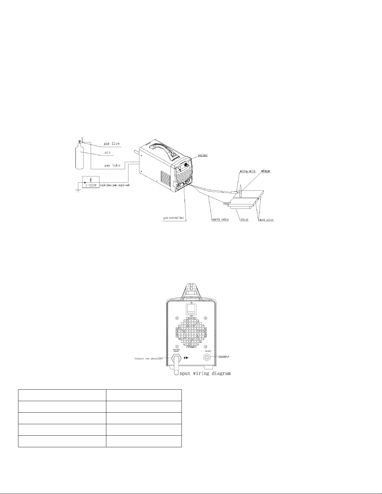
* Make sure that the welding machine has reliable earth connection.
* Make sure that there is always sound output and input wire connection instead of exposing it outside.
Regular check needs to be conducted by the qualified personnel after the welder has been installed
over a period of six months, which involves as follows:
* Routine cleaning needs to be done to make sure that there is no abnormal condition happening in the
tightened places such as the loose and slipped magnetic core, regulating screw, connecting wire
happening in the welding machine.
* The external parts installed with the welder must guarantee that the welder works properly.
* Check the welding cable to see if it can continue to be used before it is worn out.
* Replace the welder’s input cable as soon as it is found to be broken or damaged.
* Make sure whether there is enough power supply to make the welding machine work properly.
Attention: Cut off the power supply before opening the case to check.

Please do not hesitate to contact us for technical assistance whenever you come across the problems
you can not work out or you may deem difficult to fix.
3. Technical Specifications
Environment to which the Product is Subject
* The surrounding temperature range: When welding: -10~+40°C.
During transport or in storage: -25~+55°C.
* Relative humidity: when at 40 °C: ≦50%.
when at 20 °C: ≦90%.
* The dust, acid and erodible materials in the air can not exceed the amount required by the norm (apart
from the emissions from the welder ). No violent vibration at the job site.
* Altitude no more than 1,000m.
* Sound ventilation: Make sure of a more than 50cm space left near the welders.
* Keep from raining when it is used outdoor.
* The pressure of the water cooling should guarantee the required flow, the water quality should accord
with the standard of the industry water.
* The wind speed should no more than 1m/s around the operation places.
Requirement for Main Supply
* The voltage oscillogram should display actual sine wave, the oscillation of the frequency should not
exceed ±1% of the rated value.
* The oscillation of the supplied voltage should not exceed ±15% of the rated value.
Welder’s Principle (see following picture)
The 410-PROTI 20 welder applies advanced I BT(insulated gate bipolar transistor)and rapid
recovery diode as it’s the main power piece of the power transformation and transfer, with which the
arc can be minutely controlled. It is also assisted with gas pre-flow、gas post-flow and non-contact
high frequency pilot, all which contribute to the machine with the feature of high reliability and fast
dynamic response speed and stable arc.
Welding machine by air switch SW - SPST single-phase 220 v alternating current ac) power frequency, the BD1
single-phase rectifier bridge rectifier and capacitor C1 C2 C3 filtering into direct current dc), via the IGBT Q1, Q2
Q3 Q4) consisting of a full bridge inverter ac inverter into to 36 KHZ, then through intermediate frequency
transformer T1 transformer, the quick restore tube D1, D2 D3 D4 D5 D6 D7 D8 rectifier, output steady dc power
Rectifier Filter Inverter
Function
Transfor
m-ation
High Frequency
Rectifier
Drive Modulate Trait
Control
Protection
Inspect
Process
Control
Current
Adjustment
Sampling

supply for welding in the output at the same time, via high pressure of coupling transformer T2 arc with high
frequency pulse coupled to the output of the negative side, is very convenient. For non-contact arc argon arc welding.
Welder’s Structure
Portable 410-PROTIG20 products adopt can use portable box structure: the upper part on the front panel is equipped
with digital display table welding current adjustment knob 410-PROTIG20 with argon arc welding and hand welding
switch unusual light yellow); The lower part is equipped with output current + very quickly - very fast output current
socket Gas electricity integral whole joint welding gun control switch socket; Rear panel is equipped with cooling fan
power input lead gas input interface; Open the casing can be seen on the body of the upper mounting plate with 1
piece of printed circuit board control, floor is equipped with the main transformer coupling transformer; Radiator with
power device installed in the middle of the body.
Main Technical Data
Item Unit 410-PROTI 20
Rated Input Voltage V220
Frequency Hz 50/60
Phase Phase 1
Rated Input
Capacitance KVA 6.6
Rated Input Current A30
Rated No-load Voltage V58
Rated Working Voltage V18
Current Adjustment
Range(TIG)A10~200
Current Adjustment
Range(STICK )A10~160
Rated Duty Cycle %50
Cooling Type Fan-cooled
TIG welding arc striking way HF arc pilot
Selected Welding Type TI Welding / Stick
Efficiency η85%
Power Factor Cosφ 0.73
Insulating Degree Degree F
Case Protection Degree IP IP21S
Dimension L×W×H mm 360×150×270
Weight kg 5.7
Welder Standard
* EN60974-1 Arc Welding Equipment Safety Standard Part 1: Welding Power
Source

HF Arc Pilot Description
There is distinctive difference between the high frequency pilot and traditional pilot way. There is
no need to pilot by through the connection between the Tungsten electrode and the work piece, instead,
it ionizes the air by high voltage and high frequency pulse, then conducted by the ionized air so as to
form arc.
Illustration of Signs
Welding machine grounding symbol.
TI weld .
SAMW.
Power supply symbol and ac single-phase symbol.
Single phase static- frequency converter -transformer- rectifier.
Direct Current
+ : “+” Current Output
- : “-” Current Output
X:Duty Cycle
I1max...A:Rated Maximum Input Current
I1eff...A:Rated Virtual Input Current
I2:Rated Welding Current
U0:Rated No-load Voltage
U1:Rated Input Voltage
U2:Conventional Load Voltage
~50/60Hz:AC, Rated Frequency 50Hz,Usable Frequency 60Hz
...V:Conventional Load Voltage(Volt)
...A:Rated Welding Current(ampere)。
...%:Duty Cycle Unit
...A/...V~...A/...V:Output Range. Rated Maximum and Minimum Welding Current and its Load
Voltage
IP21S:IP Protection grade is a code letter International Protection International Protection) 2 refers to prevent
people close to the dangerous parts with finger; Prevent not less than 12.5 mm diameter solid foreign body into the
shell 1 refers to prevent vertical drop of water; Vertical drop of water should be no harmful effects S refers to the
moving parts of the waterproof test on the device such as a rotary motor rotor) at rest。
F:F class insulation class。

4. Installation
Placement
* The welder should be placed in the dry and clean environment which there is no chemical corrosive
articles or flammable、explosive gas.
* The welder must be installed in the place where it can not be exposed to sun and rain. Also it must be
stored in less humid place with the temperature range at -10~40°C.
* There should be 50cm space about for the cutting machine to have good ventilation.
* Apparatus to exclude wind and smoke should be equipped if the inside aeration is not sound.
Connection between elder and Power Supply(see input connection)
Input wiring diagram After welding machine panel of the power input line equipped with circuit breaker and
grounding line access to the single-phase 220 v power supply power grid); It is strictly prohibited to 380 v power
supply access welder 380 v power supply which can seriously damage the welder), it is forbidden to the earth wire
connected to the electricity grid, otherwise the consequence is proud。Notice: the power supply earth connection is
not zero connection.
Distribution for Single Welder:
Project 41 0-PROTIG20
Air switch(A)≥ 40
The fuse rated current)A40
Knife switch(A)≥60
Power line (mm2)≥4
ote: the fuse melting current is two times of the rated welding current

Connection between Welder and Argon(see input connection sketch)
Install the pressure reducing valve argon) in argon gas bottle, provided with random trachea will perfectly on the
pressure reducing valve gas interface with welding argon gas input on the rear panel interface Connect, interface with
random provide hose hoops lock。
Connection between elder and ork Piece (see output ConnectionSketch)
When using argon arc welding, with the rapid of the grounding cables plug into the socket on the front panel
welding current + very quick socket) And tighten the clockwise, grounding on the other end of the cable clamp work
piece。
When using manual welding, the grounding cables with quick plug into the socket on the front panel
welding current - very quick socket) And tighten the clockwise,grounding on the other end of the
cable clamp work piece。
Connection between Welder and Torch(see output connection sketch)
When argon arc welding, welding torch tail has two interfaces, the welding torch access interface of welding torch
is on the front panel And tighten in a clockwise; Line connect the control cable interface And tighten。
Connection between elder and Electrode Holder (see output connection sketch)Will meet
with electrode holder welding cable quickly plug into the socket on the front panel welding current + very quick
socket) And tighten the clockwise。
5. Operation (see panel sketch)
Connect work piece
After the line on the welding torch
After welding torch
interface
After the electrode
holder
Connect work
piece
Argon arc welding output wiring
diagram
Manual welding output wiring
diagram

0ATTE TIO :The protection grade of 410-PROTI 20
Welder is IP21S. It is forbidden to put in a finger or insert a round bar less than
12.5mm (metal bar in particular) into the welder. No hea y force can be employed on the
welder.The former board schematic diagram The after board schematic
diagram
1 “-” Current Output 2.Power Indicator 3welder’s handle 4Alarm Indicator
5.Welding Current
Adjustment Knob
6 Button Switch 7 as Output 8Connector for Torch
Control Line
9“+” Current Output 10 as Input 11 Power On/off
Switch
12 Power Input Cable
Attention:
* Welding machine continuous work time is too long, the protection of the panel light is bright, show that the
temperature of the welding machine internal temperature rise has been more than design value, use after period of
time shall be suspended at this time standby inner cooled down, while protecting the lights go out) may continue to
use;
* Work done or temporary leave welding on site, should shut off the power switch and argon gas valve;
* Welders should be worn denim overalls and welding mask, in order to prevent the arc and thermal radiation;
* Job site should be placed around the screen, to prevent others affected by the arc;
* Operations shall not be placed near the site flammable items;
* Welder each interface must be accurate and reliable connection。
Welding basic steps
* TIG welding
a)Before welding modulation
Set the p Set the press of a welding torch switch, argon gas flow。
The welding mode selection switch when placing in the argon arc welding can use argon arc welding。
According to the needs of welding specification: adjust welding current adjustment knob, adjustment of welding
current。
b)No-load running and function
The press of a welding torch switch, send out airflow, at the same time to hear the voice of the machine with high
frequency pulsed arc discharge; Open the switch after discharge to immediately stop, air valve delay 2 seconds or stop
to aspirate after 4 seconds。
c)TI welding
Pick up the torch, weld, the press of a welding torch switch, can ignite arc argon arc welding。
* Manual arc welding
a)Modulation and functional confirmation before welding
The welding mode selection switch when placing in manual arc welding can be used as a manual electric arc
welding。
According to the needs of welding specification adjustment welding current adjustment knob Set the welding
current。
b)welding Picked up holder, weld, placing the electrode on the work piece to wipe, can ignite arc
welding。

Attention:* At the beginning of the tungsten electrode argon arc welding flux before welding argon Ar) to blow
air can be more conducive to welding pipe net。
* High frequency arc ignition arc pulse to work long hours and cannot, should check the gas path of tungsten
electrode and welding wire for adverse factors Don't let the high frequency arc pulse to work long hours without arc
ignition!
* In the tungsten electrode argon arc welding, when at the end of the welding, let go of the welding torch button
should be completed when stagnant air end rear can remove the welding torch
, or welding joint get good protection。
Welding Criterion Parameter (For Reference Only)
Name Welding current A
3 20 15 80 70 160 100 200
Tungsten electrode diameter mm Φ 0.5 Φ 1.0 Φ 1.6 Φ 2.0
as-flow L/min 45 5 7 6 8 8 12
Nozzle specifications mm Φ 4、Φ 6、Φ 8 Φ 6、Φ 8、Φ 10 Φ 8、Φ 10 Φ 10、Φ 12
Filler wire diameter mm ≤ Φ 1.0 ≤ Φ 1.6 Φ 1.0 Φ 2.4 Φ1.6 Φ 3.0
Maintenance and Service
The most distinctive difference of 410-PROTI 20 Welder with the traditional welder is that it mostly
adopt modern electric apparatus with high level technology. It is among the list of high-tech products,
as a result higher technical requirement is asked for the maintenance personnel. However there are very
few spare parts for that type machine, so maintenance is not required very often except the routine
cleaning. Only the qualified people are allowed to be in charge of the repair job. It is strongly
recommended that customers contact our company for the technical back-up or service when they feel
unable to work out the technical hitch or problems.
The maintenance job mainly includes:
* Dust Removal
The professional maintenance personnel should use dry compressed air (air compression machine)
to move the dust inside the machine regularly. Make sure there is no abnormal condition happening in
the tightened places such as the loose and connecting wire. Eliminate the problem as soon as it
occurs. In the case when the dust is easily to accumulate, it should be cleaned in time. Usually the
machine should be cleaned once a year if the dust accumulation problem is not very serious, while it
needs cleaning once or even twice every quarter if the dust accumulation problem is serious.
* Make sure that the connection of welding cable socket is in sound condition.
Regular check should be taken on the connection condition of the welding cable socket. The
operator should check it at least once a month for the fixed machine, while the operator should check
every time before using for the moveable machine.
ATTE TIO :
* The welder main loop voltage is always higher, so the safety precaution should be taken
before
repairing to avoid accidental shock. Under no circumstance can anyone except the
professionally trained personnel open the case of the machine.
* Switch off the power source each time when removing dust.
* Never tamper with inside cable or damage the component parts while removing dust.

6. Trouble Shooting
NO Faults Phenomenon Faults Cause Analysis
1 Abnormal indicator light is on Machine overheating Go back to normal after
temperature has dropped
2Draught fan fails to work Draught fan breaks down Exchange draught fan
Connect wire falls off
disconnection)
Find out the br oken wi re and
reconnect it re liable
3Non-high frequency for arc strike welding g u n switcher bre a k s
down
Exchange welding gun
switcher
Connect wire falls off
disconnection)
Find out the br oken wi re and
reconnect it re liable
4No argon output No argon input Check flowmeter and ai r pipe
and recover the air supply
Electropneumatic valve breaks
down
Exchange lectropneumatic
valve
Gas circuit b locks Exclude foreign body and
dredge gas path
5Non-adjustabl e Electric current Potentionmeter breaks down Exchange potentionmeter
Connect wire falls off
disconnection)
Find out the br oken wi re and
reconnect it re liable
6Arc strike obstruct Connection between welding gun
and main engi ne error
Check and correct it
according to specification
Argon is impurity Use 99.9 9 percen t pure argon
Tungsten el ectrode is not good or
the needle bre aks down
Use qualified tungsten
electrode
7Power switch trip The power capacity is not enough Increase the power capacity
8others Please contact the manufacturer or
distributor

Schematic of Portable410-PROTIG20 Welding Machine
(Figure for reference, any update without notification)
9. Complete Set Specification
* Portable 410-PROTI 20 inverter DC arc welding
machine
1pcs
* Product Certificate 1pcs
* Operator’s Manual 1pcs
Accessories and Consumable
* Torch 1pcs
* Pottery nozzle (with one on the torch) 3pcs
* Tungsten electrode holder (with one on the torch) 3pcs
* Earth Cable(with earth clamp and quick connector)1pcs
Remarks: a) No guarantee has been made yet to get the welding accessories repaired at any time
because of its breakable attribute.
b) If there is any stipulation in the contract, then base on the contract.
10. Transport & Storage
* This series is chest structure, hold the handle or the bottom to move it. The machines should be firmly
fixed during the transportation.
* The machines should be free from rain and snow. Keep notice of Attention sign on the packing box.
The storage ware should keep dry and air circulation & free from corrosive gas or dust. The tolerable
temperature ranges from -25% to +55%, and the relative humidity can not be more than 90%.
* After the package has been opened, it is suggested to repack the product as per requirement for future
storage and transport. (Cleaning job is required before storage and sealing the plastic bag for storage
in the box.)
* Users should keep the packing materials with the machines to keep well storage during the long
transportation. If the machines need transfer during the transportation, then wooden box is required.
Sign such as ‘Lift’ and ‘Free of rain’ should be labeled on the box.
Table of contents
Popular Inverter manuals by other brands

Danfoss
Danfoss EM-PMI375 user guide

Astrel Group
Astrel Group Power Reducer Installation and instruction manual

NEP
NEP BDM-300X2-240A-D Installation and operation manual

Epever
Epever Sunshine Solar IP350-Plus user manual

SifWeld
SifWeld ST180 PRO Operation manual

Carrier
Carrier ASPAS1CCA012 Parts, adjustment and maintenance manual

Zgonc
Zgonc yellow PROFILINE YPL 6000-D Translation of original instruction manual

Atlas Copco
Atlas Copco QAS366 Gd USA instruction manual

Goodwe
Goodwe DNS Series user manual

Stanley
Stanley FATMAX PCI140CA instruction manual

DRIVELONG
DRIVELONG SE2000i owner's manual

Expion360
Expion360 EX-AURA002 user manual