4
3. Install the clamp on ferrite bead provided in the kit (Fair-rite part number 0446164281 or
equivalent) 2.5 cm from the molded end of the Ethernet cable that plugs into the radio’s Ethernet
port.
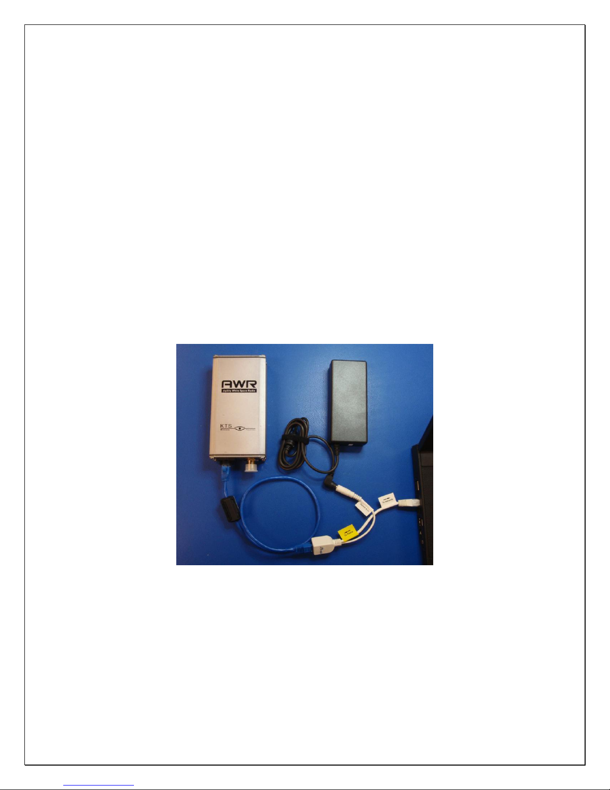
4. Connect a laptop and power supply to the AWR as shown. Failure to connect the PoE injector and
power supply correctly can damage a connected device. Do not use a crossover terminated
Ethernet cable. The AWR requires approximately 10 seconds to initialize.
Set the computers IP Address to a static IP address on the same subnet as the AWR (e.g.,
192.168.1.100). The default IP Address for new AWR radios is 192.168.1.4 with an IP Gateway
address of 192.168.1.1. When the laptop and AWR are connected together and powered on, use the
default IP Address to access and configure each new device prior to deployment using the EMS
application.
Each new AWR is preconfigured as a Spoke radio as shown on the Element Manager’s Device Info
tab. All AWR’s destined to be network Hubs must have its Node Type changed to a Hub using the
Node Type dropdown box. Select the desire node type and “save”the configuration to the radio
using the EMS tool. The latitude and longitude where each radio is to be installed must be entered
using the White Space tab. This information is provided to the White Space database so that the
correct list of available channels can be sent to the radio.
Note: The AWR should not be powered on without an antenna connected to the RF connector.
5. Installation of the EMS software provided with the AWR is required in order to manage the AWR
devices. Insert the included CD into a computer and double click on the installation file:
TVBD_Installer.exe. Follow the prompts to complete the EMS software installation process. The
software installation process is described in detail in Section Error! Reference source not found..
6. The mounting bracket, grounding cable and weather resistant RJ45 cap assembly is shown below. A
thermal pad with adhesive is also included. Installing this thermal pad will reduce the operating