KUHN GA300GM User manual

Original instructions
KN125DGB B
Read carefully before starting the machine
Operator's manual
Gyrorake
---A1034-00D00001 > ---A1034-00D99999
GA300GM
KN125DGB B - English - 08-2019
*KN125DGB_B*


1. - Dear Owner
GA300GM
1
KN125DGB B
Gyrorake
1. Dear Owner
In buying a Kuhn machine you have chosen wisely. Into it have gone years of thought, research and
improvement. You will find, as have thousands of owners all over the world, that you have the best that
engineering skill and actual field testing can produce. You have purchased a dependable machine, but only
through proper care and operation can you expect to receive the performance and long service built into it.
This manual contains all the necessary information for you to receive full efficiency from your machine. The
performance you get from this machine is largely dependent on how well you read and understand this
manual and apply this knowledge. Please DO NOT ASSUME YOU KNOW HOW TO OPERATE AND
MAINTAIN YOUR MACHINE before reading this manual carefully. KEEP THIS MANUAL AVAILABLE FOR
REFERENCE. Pass it on to the next owner if you re-sell the machine.
Your KUHN dealer can offer a complete line of genuine KUHN service parts. These parts are manufactured
and carefully inspected in the same factory that builds the machine to assure high quality and accurate
fitting of any necessary replacements.
About improvements
We are continually striving to improve our products. We therefore reserve the right to make improvements
or changes when it becomes practical to do so, without incurring any obligations to make changes or
additions to the equipment sold previously.
Wear parts
Wearing parts fitted on our machines have been tested in very different situations to optimize their service
life. Nevertheless, the service life depends highly on theconditions of use (products to handle, soil, weather
conditions, etc...).
Document illustrations
The illustrations in this manual may be based on one type of machine only. However, all instructions apply
to all machines covered in this manual.
Copyright 2019 KUHN

GA300GM
22. - Contents KN125DGB B
Gyrorake
2. Contents
1. Dear Owner .....................................................................................................................1
2. Contents..........................................................................................................................2
3. Identification of the machine.........................................................................................5
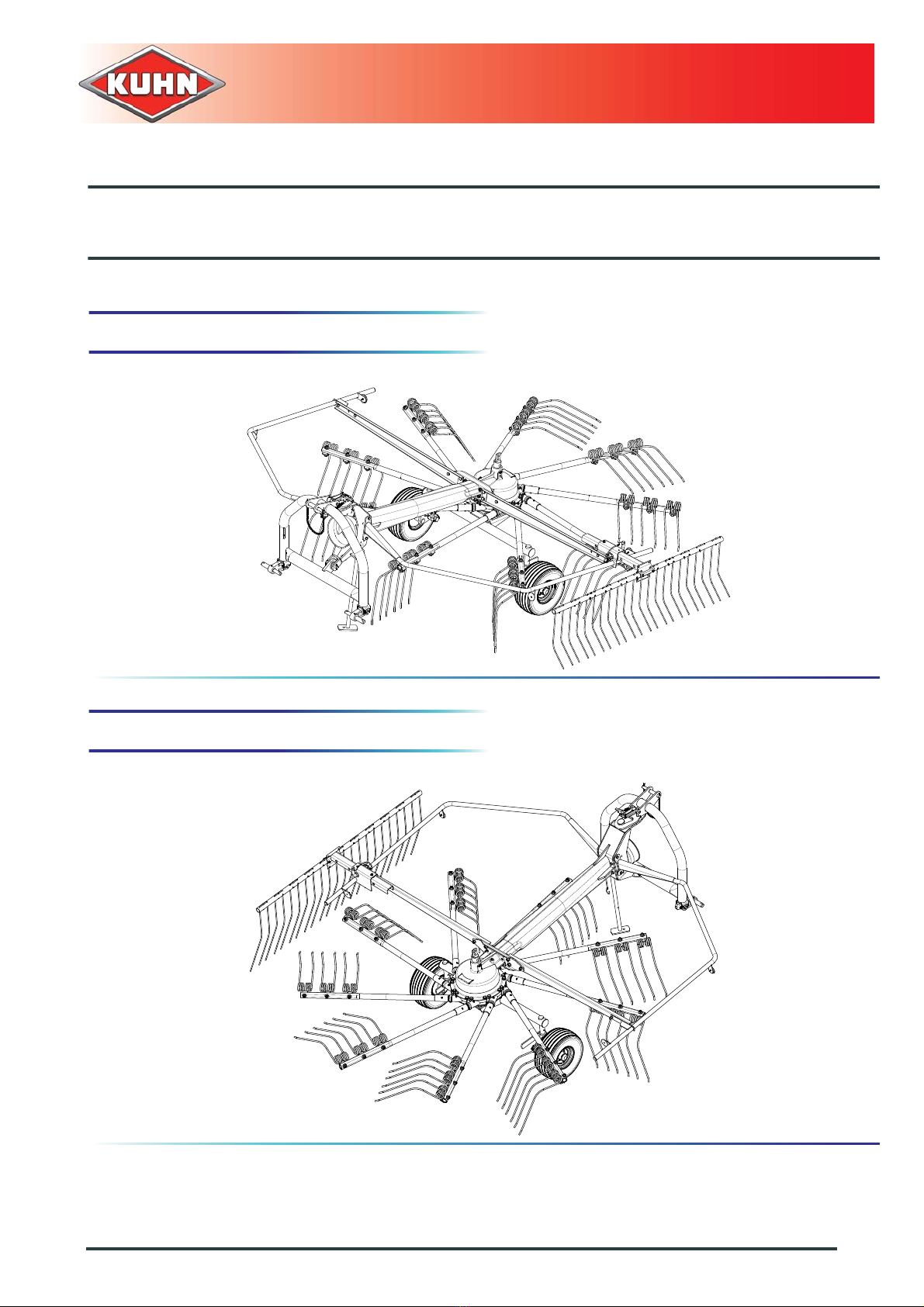
3.1 Front view ........................................................................................................................................ 5
3.2 Rear view (working position)............................................................................................................ 5
3.3 Identification of the machine............................................................................................................ 6
3.4 Optional equipment.......................................................................................................................... 8
4. Safety...............................................................................................................................9
4.1 Description of symbols used in this document.................................................................................9
4.2 Safety instructions ......................................................................................................................... 10
4.2.1 Introduction....................................................................................................................... 10
4.2.2 Read and follow the safety instructions............................................................................ 10
4.2.3 Safety decals.....................................................................................................................11
4.2.4 Precautions to be taken before carrying out any operations on the machine....................11
4.2.5 Precautions to take before using the machine ................................................................. 12
4.2.6 Precautions when driving .................................................................................................13
4.2.7 Precautions when driving on public roads........................................................................14
4.2.8 Maximum speed...............................................................................................................18
4.2.9 Precautions when coupling...............................................................................................18
4.2.10 PTO shaft..........................................................................................................................19
4.2.11 Precautions during manoeuvres....................................................................................... 21
4.2.12 Remote controlled components........................................................................................21
4.2.13 Waste disposal .................................................................................................................21
4.2.14 Tyres................................................................................................................................. 21
4.2.15 Precautions for maintenance and repair work.................................................................. 22
4.2.16 Projection of stones and foreign objects........................................................................... 23
4.2.17 Precautions for machine use............................................................................................ 24
4.2.18 Precautions to take before using the parking stands........................................................ 24
4.3 Location and description of safety decals on the machine ............................................................ 25
4.3.1 Location of safety decals..................................................................................................25
4.3.2 Description of safety decals..............................................................................................26

2. - Contents
GA300GM
3
KN125DGB B
Gyrorake
-4.4 Likely critical failures...................................................................................................................... 28
4.5 Incorrect use of the machine by the user ...................................................................................... 28
4.6 Limit state criteria........................................................................................................................... 28
5. Machine specifications................................................................................................ 29
5.1 Description and glossary ............................................................................................................... 29
5.2 Technical specifications................................................................................................................. 30
5.2.1 Designated parameters.................................................................................................... 30
5.3 Sound levels.................................................................................................................................. 31
6. Putting into service...................................................................................................... 32
6.1 Coupling and uncoupling............................................................................................................... 32
6.1.1 Description of coupling elements ..................................................................................... 32
6.1.2 Preparing the tractor......................................................................................................... 32
6.1.3 Coupling the machine.......................................................................................................34
6.1.4 Electrical connections....................................................................................................... 36
6.1.5 Pto shaft........................................................................................................................... 37
6.1.6 Uncoupling the machine................................................................................................... 40
7. Instructions for transport............................................................................................ 42
7.1 Putting the machine into transport position ................................................................................... 42
7.2 Conformity with the road regulations............................................................................................. 44
7.3 Machine transport using transport means ..................................................................................... 44
8. Instructions for work................................................................................................... 45
8.1 Putting the machine into work position.......................................................................................... 45
8.2 Adjustments in working position .................................................................................................... 47
8.2.1 Wheel height adjustment.................................................................................................. 47
8.2.2 Swath screen adjustment................................................................................................. 49
8.3 Machine use .................................................................................................................................. 52
8.3.1 Drive speed...................................................................................................................... 52

GA300GM
42. - Contents KN125DGB B
Gyrorake
-
9. Optional equipment......................................................................................................53
9.1 Front support wheel.......................................................................................................................53
9.1.1 Settings............................................................................................................................. 53
9.1.2 Instructions for transport...................................................................................................54
9.1.3 Instructions for work ......................................................................................................... 55
9.2 Bogie axles .................................................................................................................................... 56
9.2.1 Machine use.....................................................................................................................56
9.2.2 Lubrication........................................................................................................................ 57
9.3 Lateral signalling equipment..........................................................................................................58
9.4 Europe signalling equipment .........................................................................................................59
9.4.1 Coupling and uncoupling.................................................................................................. 59
9.5 USA signalling equipment.............................................................................................................. 60
9.5.1 Coupling and uncoupling.................................................................................................. 60
10. Maintenance and storage ............................................................................................61
10.1 Frequency chart............................................................................................................................. 61
10.2 Lubrication .....................................................................................................................................62
10.2.1 PTO shaft.......................................................................................................................... 62
10.2.2 Rotor................................................................................................................................. 63
10.2.3 Lubricate the following parts.............................................................................................64
10.3 Maintenance .................................................................................................................................. 66
10.3.1 Checking the fixing elements............................................................................................66
10.4 Storage .......................................................................................................................................... 67
10.4.1 At the end of each season................................................................................................67
10.4.2 At the start of each season...............................................................................................67
11. Troubleshooting guide.................................................................................................69
12. Appendix.......................................................................................................................71
12.1 Calculating the load on an axle...................................................................................................... 71
13. Limited Warranty ..........................................................................................................78

3. - Identification of the machine
GA300GM
5
KN125DGB B
Gyrorake
3. Identification of the machine
3.1 Front view
3.2 Rear view (working position)

GA300GM
63. - Identification of the machine KN125DGB B
Gyrorake
3.3 Identification of the machine
3.3.1 Location of the plates
3.3.2 Description
Do not remove the manufacturer, homologation and marking plates attached to the machine.
Note the serial number of your machine:
• Serial Number:
This information is to be given to the Kuhn
authorized dealer for any spare parts order or
warranty claim.
Model identification plate
1: Manufacturer name and address
3: Brand
4: KUHN logo
5: Description of the machine
7: Model
9a: Machine serial number
9b: Barcode (Machine serial number)
12: Weight empty (Minimum/Maximum)
18: Data matrix
19: Plate reference
27: Place of manufacture
28: Manufactured by... for...
34: Special operation
9: Serial Nr. 34: Ex
5: Machine
7: Model
09993000
3: Brand
kg
kg
12: Unladen Mass min/Max
3: 商 Brand
9: 机架号 Serial Nr. 34: Ex
5: 机器描述 Machine
7: 型号 Model
kg
12: 卸重量最小/最大Unladen Mass min/max kg
1
34
18
19
3
9a
5
7
12
28
27
9b
4

3. - Identification of the machine
GA300GM
7
KN125DGB B
Gyrorake
Certification plate (CE)
For machines aimed at countries which are
members of the European Union (EC marking).
4: KUHN logo
7: Model
9: Machine serial number
19: Plate reference
23: Logo CE
24: Manufacturing year
26: Model year
54: Data matrix
24: Year of Construction
26: Model Year
7: Model
9: Serial Nr.
23
54
4
19
7
9
24
26
Certification plate (EAC)
For machines aimed at countries member of the
Eurasian customs union (EAC marking).
4: KUHN logo
7: Model
9: Machine serial number
19: Plate reference
23: Logo EAC
25: Manufacturing year
26: Model year
54: Data matrix
25: Month-Year of Construction
26: Model Year
7: Model
9: Serial Nr.
23
54
4
26
25
7
9
19
Importer plate (BRASIL)
For machines to be sent to Brazil.
1: Manufacturer name and address
4: KUHN logo
7: Model
9: Machine serial number
19: Plate reference
24: Manufacturing year
54: Data matrix
24: Year of Construction
19
54 4
1
24
97

GA300GM
83. - Identification of the machine KN125DGB B
Gyrorake
3.4 Optional equipment
Tick box corresponding to the equipment fitted on
your machine:
Front support wheel.
Bogie axles.
Europe signalling equipment.
USA signalling equipment.

4. - Safety
GA300GM
9
KN125DGB B
Gyrorake
4. Safety
4.1 Description of symbols used in
this document
This symbol indicates a potentially hazardous
situation that if not avoided, could result in serious
bodily injury.
This symbol is used to identify special instructionsor
procedures which, if not followed strictly, could
result in machinery damage.
This symbol is used to communicate technical
information of particular interest.

GA300GM
10 4. - Safety KN125DGB B
Gyrorake
4.2 Safety instructions
4.2.1 Introduction
The machine must only be operated, maintained and repaired by competent persons who are familiar with
machines' specifications and operation and aware of safety regulations for preventing accidents.
The operatormust imperatively respect safety instructions in this manual and in the warnings posted on the
machine. The operator is also obliged to respect current legislation concerning accident prevention, work
safety and public traffic circulation.
Designated use of the machine also means following operation, maintenance and repair recommendations
given by the manufacturer, and using only genuine spare parts, equipment and accessories, as
recommended by the manufacturer.
The manufacturer is not held liable for any damage resulting from machine applications other than those
specified by the manufacturer. Any use other than the designated operation is at the risk and responsibility
of the operator.
The manufacturer is not held liable forany damage or accident resulting from machine modifications carried
out by the operator himself or by a third party without previous written agreement from the manufacturer.
4.2.2 Read and follow the safety instructions
Before using the machine, carefully read all the
safety instructions in this manual and the warnings
placed on the machine.
Before starting work, the operator must be familiar
with all machine controls, handling devices and their
functions. It is too late to learn once work has been
started!
Never let anyone operate the machine who is not
trained to do so.
Should you have any difficulties in understanding
any parts of this manual, please contact your KUHN
dealer.

4. - Safety
GA300GM
11
KN125DGB B
Gyrorake
4.2.3 Safety decals
Safety warning decals are placed in pictorial form on various parts of the machine. They are there to warn
you of potential dangers and to tell you how to avoid accidents.
Always keep the safety decals clean and readable, and replace them when they are worn, damaged,
missing or illegible.
4.2.4 Precautions to be taken before carrying
out any operations on the machine
Before leaving the tractor or before adjusting,
maintaining or repairing the machine, disengage the
PTO drive, turn off the engine, remove ignition key
and wait until all moving parts have come to a
complete stop and apply park brake.

GA300GM
12 4. - Safety KN125DGB B
Gyrorake
4.2.5 Precautions to take before using the
machine
Do not wear loose clothing which could become
caught up in moving parts.
Wear the appropriate protective clothing for the
work in hand (gloves, shoes, goggles, helmet, ear
defenders, etc.).
Ensure that all operating controls (ropes, cables,
rods, etc) are placed so as they cannot be operated
unintentionally and cause damage or injury.
Before operating the machine, check tightness of
nuts and bolts, particularly on fixing elements (tines,
forks, blades, knives, etc). Retighten if necessary.
Before operating the machine, ensure that all the
safety guards are firmly in place and in good
condition. Immediately replace any worn or
damaged guard.

4. - Safety
GA300GM
13
KN125DGB B
Gyrorake
4.2.6 Precautions when driving
Tractor handling, stability, performance and braking
efficiency are all affected by weight distribution,
trailed or mounted implements, additional ballast
and driving conditions. It is therefore of great
importance that the operator exercises caution in
every given situation.
Groundspeed must be adapted to ground conditions
as well as to roads and paths. Always avoid abrupt
changes of direction.
Be particularly cautious when turning corners,
paying attention to machine overhang, length, height
and weight.
Never use a narrow track tractor on very uneven or
steeply sloping ground.
Never leave the tractor seat while the machine is
operating.
Carrying people or animals on the machine when
working or in transport is strictly forbidden.

GA300GM
14 4. - Safety KN125DGB B
Gyrorake
4.2.7 Precautions when driving on public
roads
Dimensions
Depending on the dimensions of the machine,
contact the relevant authorities to ensure that it can
be legally transported on public roads.
If the machine is over the maximum legal size,
follow the local regulations forspecial transportation
of oversize equipment.
Transport position
Before transporting the machine on public roads,
place the machine into its transport position,
according to the instructions in this manual.
Lights and indicators
Before transporting the machine on public roads,
ensure that all legally required lightings and
signallings are in place.
Ensure that lightings and signallings are clean and
in good working order. Replace any missing or
broken equipment.
Always obey current regulations for driving
on roads.

4. - Safety
GA300GM
15
KN125DGB B
Gyrorake
Gross weight and weight per axle
Description of symbols
The drawings are not legally binding, their only aim is to illustrate the method to use.
Prior to driving on public roads, check that all criteria are met to be in conformity with the
countrie's regulations:
- When coupling a tool to the front and/or rear 3-point lift linkage, the maximum authorized
payload must not be exceeded.
- When coupling tools to the front and/or rear 3-point lift linkages, the maximum load on tractor's
tires must not be exceeded.
- The load on the tractor front axle must always represent 20 % of the tractor unladen weight.
For machines with hoppers or tanks:
- If the total unit weight exceeds the tractor Gross Combined Weight Rating in accordance with
the countrie's legislation, empty the hopper to travel on public roads.
- In any case, we recommend to travel on public roads with empty hoppers and tanks.
Description Units Description
Tkg Tractor unladen weight
PTAC kg Gross Combined Weight Rating
T1 kg Unladen load on tractor front axle
T2 kg Empty load on tractor rear axle
tkg Axle loads (Tractor + machine)
t1 kg Load on front axle (Tractor + machine)
t2 kg Load on rear axle (Tractor + machine)
t1 max kg Maximum load authorized on the tractor front axle according to the
tires
t2 max kg Maximum load authorized on the tractor rear axle according to the
tires
M1 kg Total weight of front tool or front ballast

GA300GM
16 4. - Safety KN125DGB B
Gyrorake
How to proceed:
Stage 1:
Stage 2:
To measure:
Tractor tare (T).
T = _____kg
T = ________ kg
- Couple the machine to the tractor.
To measure:
- Load on front axle (t1):
• Tractor + machine (transport position).
To do:
- If the front axle load (t1) is below 20% of the tractor
tare (T), add ballast weights (M1) to exceed the
minimum load on the front axle.
Example:
• (T) = 7500 kg (16535 lb)
• 20% of T = 1500 kg (3300 lb)
• (t1) = 700 kg (1545 lb).
• 700 kg (1545 lb) < 1500 kg (3300 lb).
- Add ballast weights until the minimum front axle
load is exceeded.
- Repeat checking procedure.
t1 = _____kg
t1 = ________ kg
t1 < 20% Tt1 < 20% T
t1t1 ≥20% T20% T

4. - Safety
GA300GM
17
KN125DGB B
Gyrorake
Stage 3:
Stage 4:
To measure:
- Total weight (t):
• Tractor + machine (transport position).
• Ballast weights.
Checking:
- To go to the next stage:
• Check in the tractor's operator's manual that the
value measured is below the tractor's Gross
Combined Weight Rating.
To do:
- If t < PTAC go to the next stage.
- If the total unit weight exceeds the tractor Gross
Combined Weight Rating in accordance with the
countrie's legislation, empty the hopper to travel on
public roads.
Example:
• (t) = 10000 kg (22046 lb).
• PTAC = 13000 kg (28660 lb).
• t < PTAC: Go to the next stage.
kgkg
t = _____kg
t = ________ kg
To measure:
- Load on rear axle (t2):
• Tractor + machine (transport position).
• Ballast weights.
Checking:
- Check in the tractor's operator's manual that the
value measured is below the maximum allowed
tractor rear axle load.
- Check that tyre and rim specifiations are in
conformity with the requirements of the tractor
manufacturer.
Example:
• Load on rear axle (t2) = 8500 kg (18740 lb).
• Check in the tractor's operator's manual that the
value measured is below the maximum allowed
tractor rear axle load.
• Check that tyre and rim specifiations are in
conformity with the requirements of the tractor
manufacturer.
kgkg
t2 = _____kg
t2 = ________ kg
t2 > t2 maxt2 > t2 max
t2t2 ≤t2 maxt2 max

GA300GM
18 4. - Safety KN125DGB B
Gyrorake
4.2.8 Maximum speed
Always keep to the legal speed limit for driving a tractor-machine assembly on public roads.
4.2.9 Precautions when coupling
Before attaching the machine, make sure that it
cannot accidentally start moving (chock the wheels)
and that the parking stand is in the right position.
The machine must only be attached to the hitch
points provided for this purpose.
Do not stand between the machine lower hitching
points or between the tractor lower hitching points
during coupling maneuvers.
Never stand between the tractor and the machine
when operating the three point linkage.
Do not stand between the machine and the tractor or
on the machine without having first applied the
tractor parking brake and placed the gearbox in the
neutral position.
Table of contents
Other KUHN Lawn Mower manuals

KUHN
KUHN GMD600GII User manual

KUHN
KUHN GMD702 GII User manual

KUHN
KUHN GMD33 N User manual

KUHN
KUHN FA 392 User manual

KUHN
KUHN SpeedRake SR108 GII User manual

KUHN
KUHN GMD 602 F User manual

KUHN
KUHN FC250RG User manual

KUHN
KUHN GMD883 User manual

KUHN
KUHN FC3160 TCR User manual

KUHN
KUHN GMD 801 User manual
Popular Lawn Mower manuals by other brands

Snapper
Snapper ODP21400 Safety instructions & operator's manual

Flymo
Flymo RE 32 instruction manual

Scag Power Equipment
Scag Power Equipment STC48V-24BS Operator's manual

Grizzly
Grizzly BRM 4613-20 A E-Start Instructions for use

Ozito
Ozito ELM-300 instruction manual

Villager
Villager Villy 4000 E Original instruction manual