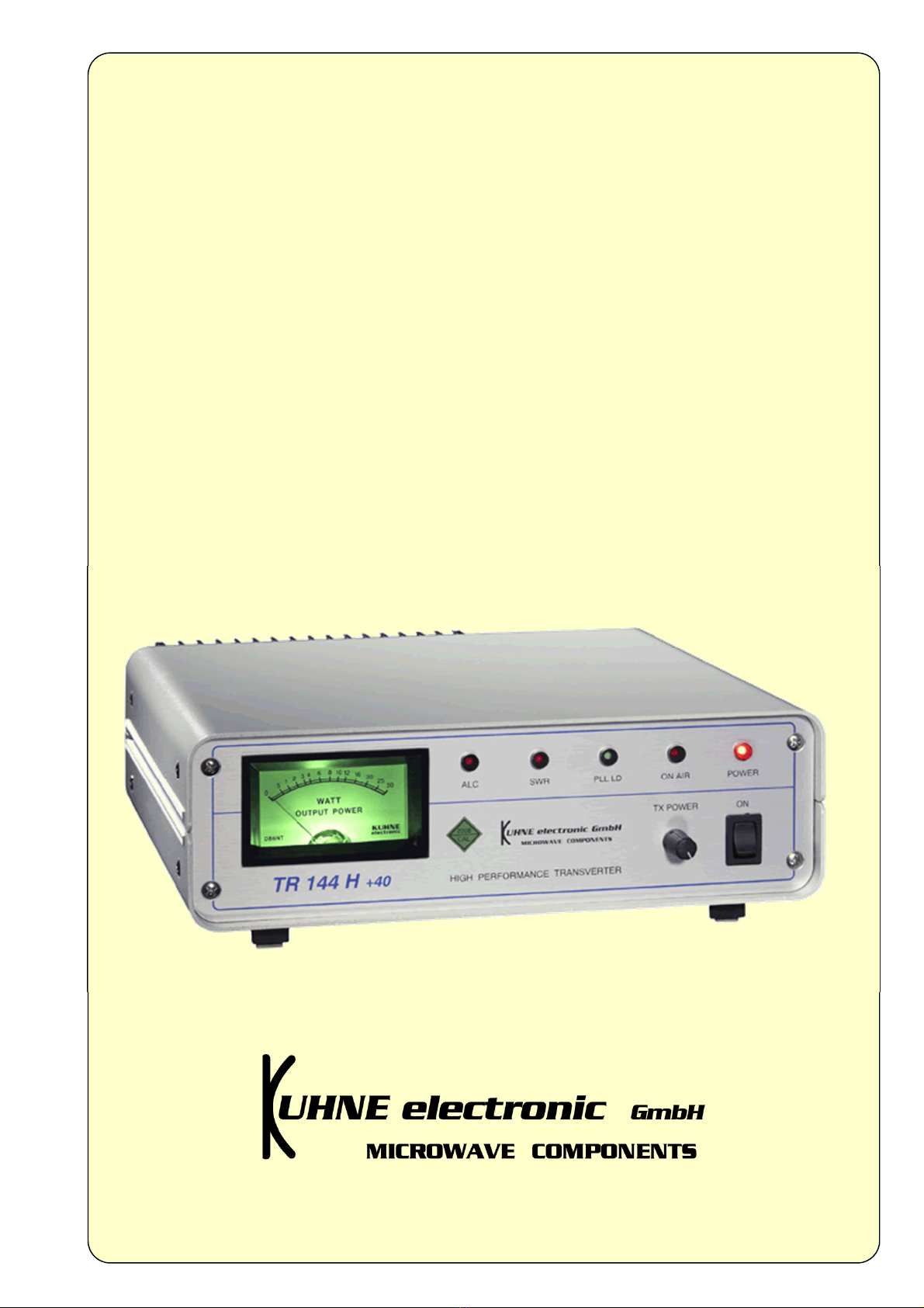
Kuhne electronic TR 144 H +40 User manual

Manual
144 MHz Transverter
DB 6 NT
© DB 6 NT
1.2015
TR 144 H +40

TR 144 H +40
Type TR 144 H +40
VHF Frequency range 144...146 MHz
IF Frequency range 28...30 MHz
IF Input power 1... 0 mW, adjustable /
switchable to range 60 ... 1000 µW
LO accuracy @ 18 °C typ. +/- 2 ppm, max. +/- 3 ppm
(without 10 MHz reference frequency)
LO frequency stability (0 ... +40 °C) typ. +/- 2 ppm, max. +/- 3 ppm
(without 10 MHz reference frequency)
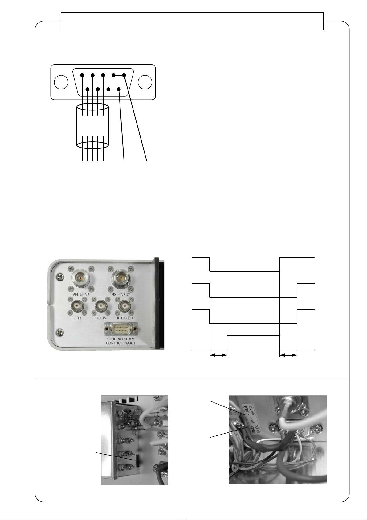
PTT control Contact closure to ground
Output power 2 W
IM3 - 32 dBc @ 20 W PEP
Supply voltage 13.8 V DC (12...14 V)
Current consumption typ. 6 A (TX)
Noise figure @ 18 °C typ. 1.2 dB
External reference input 10 MHz / 2 ... 10 mW
RX Gain typ. 2 dB
IP3 out typ. +40 dBm, min. +37 dBm
Blocking min. -106 dBc @ 3 kHz BW
IM-Dynamic min. 102. dB SFDR @ 3 kHz BW
Image rejection typ. 90 dB
Dimensions (mm) 270 x 260 x 80
Case Aluminium
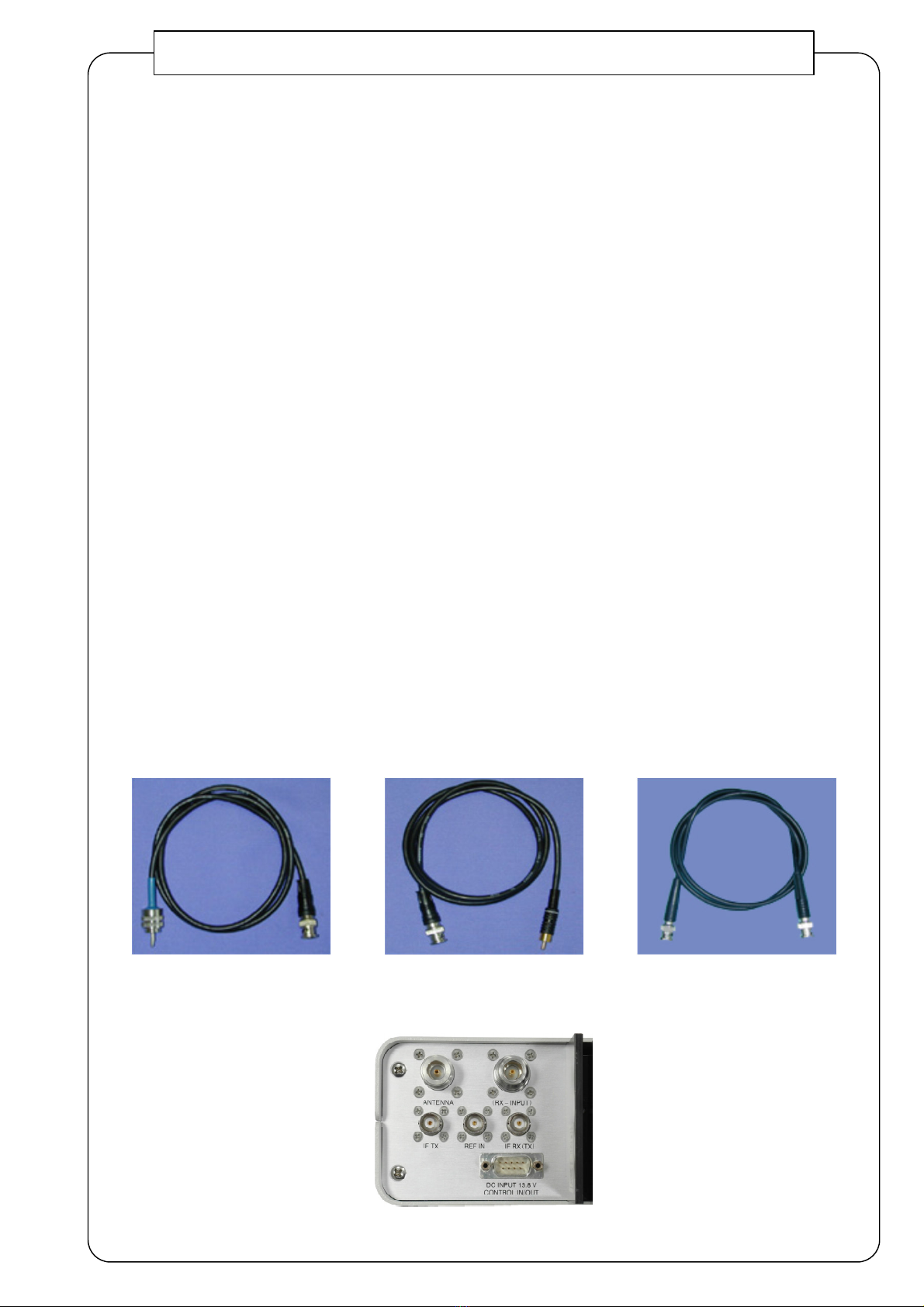
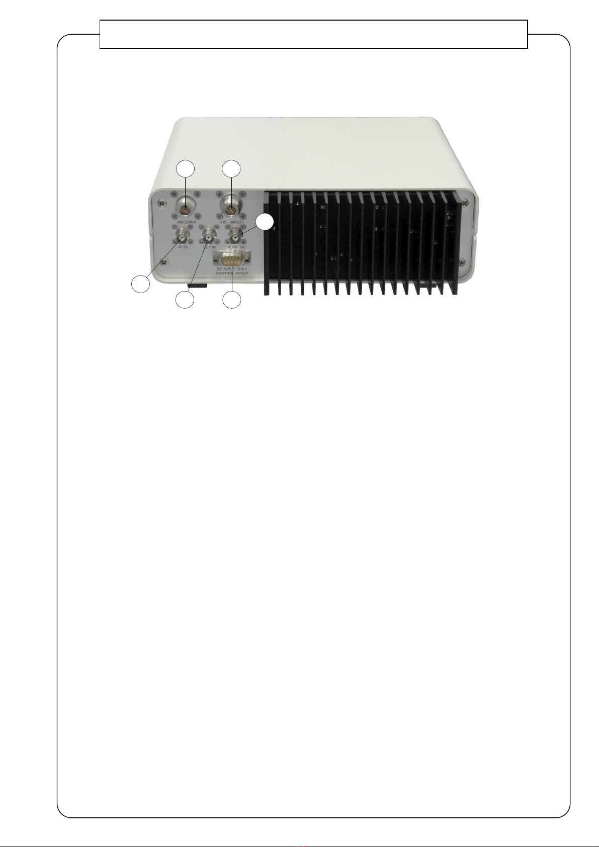
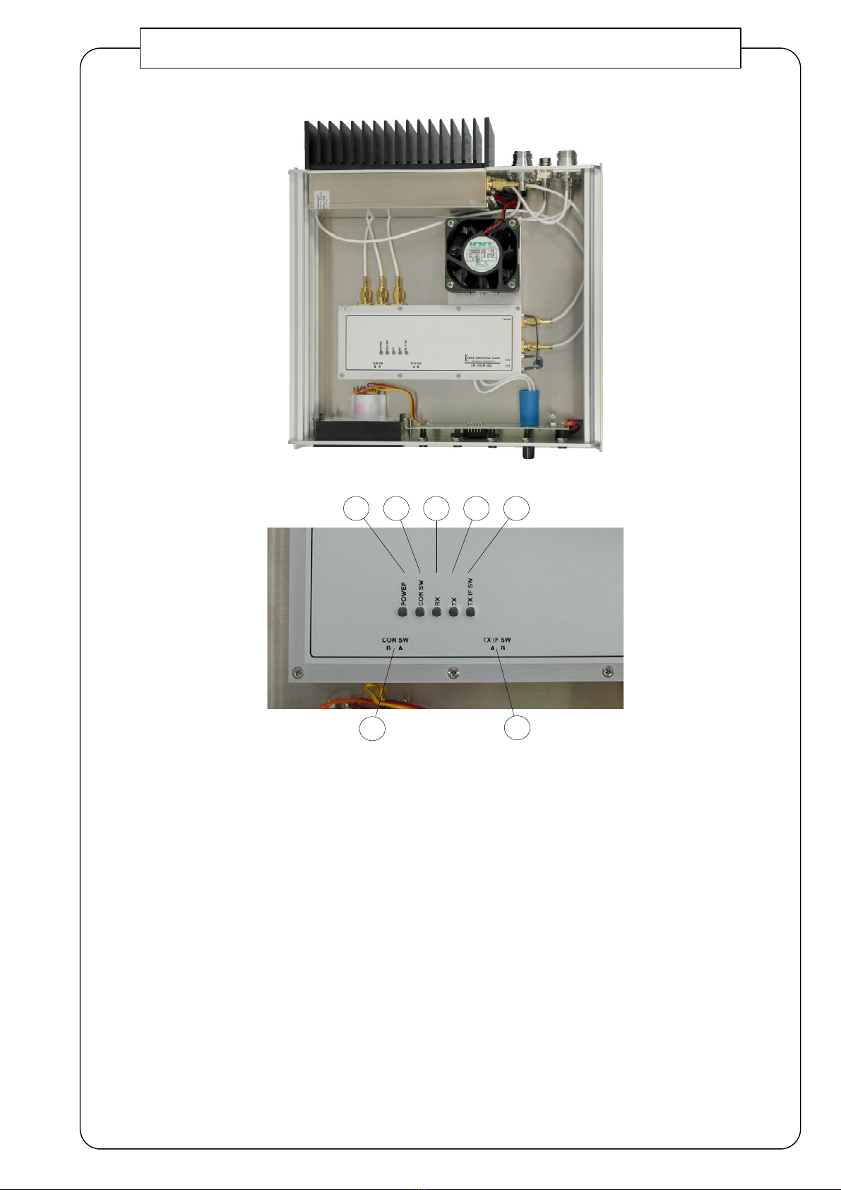
IF connectors BNC-female / 0 ohms
There are two separate IF connectors.
They can be switched to one common
IF connector
RF connectors N-female / 0 ohms
DC supply and control connector SUB-D 9-pole
Features
- Aluminium case with a big heat sink
- Internally wired with silver plated Teflon
coaxial cable
- Antenna relay with 70 dB isolation
- Converter with excellent large-signal
performance
- Big case for additional filters and other
components
- Built-in directional coupler for calibrated
power output control
- Power amplifier with built-in VSWR
protection
- -pole low-pass filter for harmonic
rejection
- Spurious and harmonic rejection better
than 60 dBc
- Low noise butler oscillator with
adjustable frequency;
40 °C precision crystal heater
- Phase noise of the oscillator better
-1 6 dBc/Hz @ 10 kHz
- Built-in sequence control
- Cable for control and DC supply
included
- Handbook included
Hig Performance 2 m Transverter
Several decades of engineering and production of Transverters result in t is new designed ig
performance Transverter TR 144 H +40. Its outstanding tec nical data make it usable for many
applications. T e transverter was originally designed for VHF amateur radio applications, for example
ig performance contest stations. T e receive pat of t e transverter provides very good large-signal
performance. T e new design of our transverter for 144 MHz features better performance and many new
functions.
Now, an external 10 MHz reference
frequency can be connected to ac ieve
ig est frequency accuracy. T is is
necessary for EME and WSJT. T e
frequency of 10 MHz can be supplied by a
ig ly stable OCXO, a reference oscillator
of a frequency counter, a rubidium
frequency standard or a GPS controlled
frequency source.
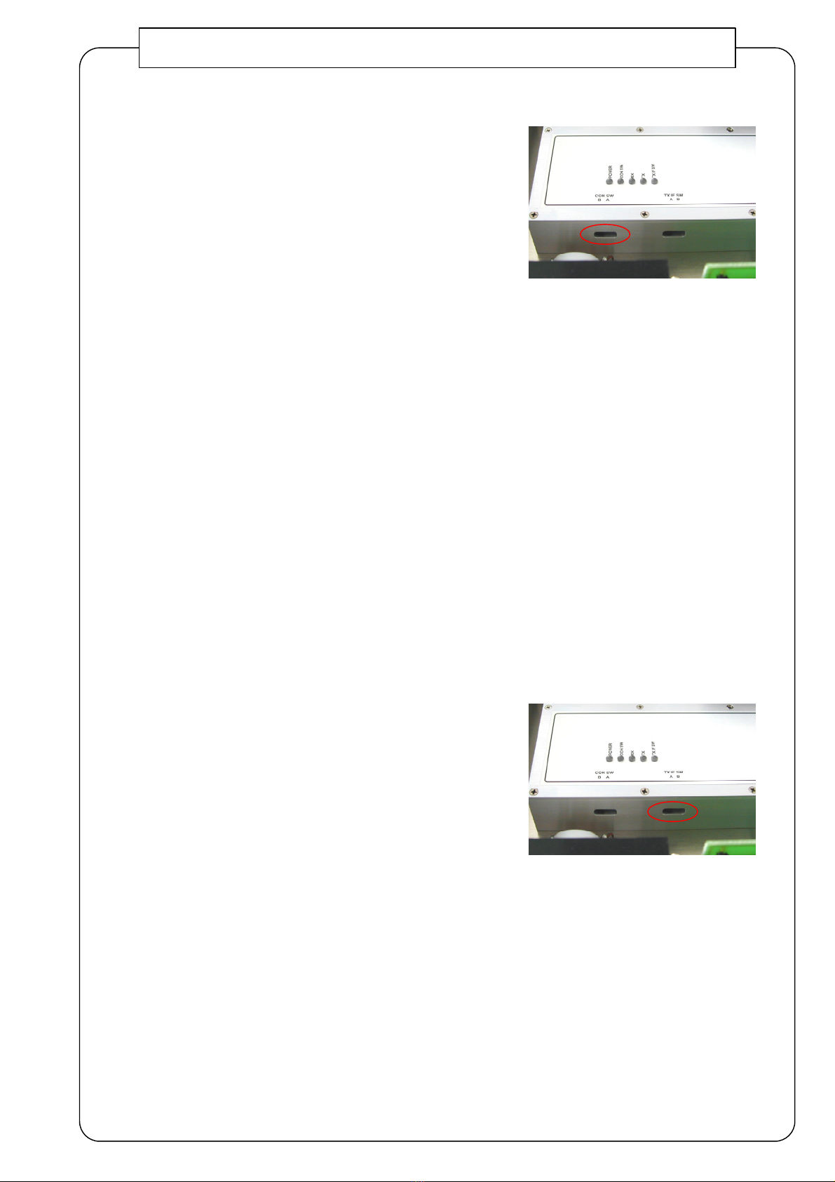
T e new design includes t e “old” options 02 (TX IF input power 60...1000 µW / 0...-12 dBm) and 06
(common IF-connector for RX/TX). So t e Transverter is compatible to most of t e used HF transceivers
wit transverter output. T e TX IF input ranges and t e IF connector configuration can be done wit t e
internal switc es of t e transverter. T e “old” option 04 (drive gain control on t e front panel) is
standard now.

TR 144 H +40
Oscillator
A temperature-compensated low noise butler oscillator generates the 116 MHz LO signal. A thermostat crystal with a 40 °C
precision crystal heater is used. Phase noise of the output signal is -1 6 dBc/Hz @ 10 kHz. This value is better than that of
the HF transceivers. The oscillator output power is 100 mW.
Receiver
In the receiver frontend there is only one balanced super low noise stage with two Power GaAs-FETs. A noise figure (NF) of
0.9 dB and an output IP3 of min. 40 dBm are achieved. To prevent interference in case of multi-band operation, there is a
notch filter for the 70cm band at the input. The prestage is followed by a high-Q helical filter and a matching network. A high-
level triple-balanced GaAs-FET ring mixer with an IP3 of min. 3 dBm converts the signal to the intermediate frequency (IF) at
28…30 MHz. The total gain of the receiver path is limited to 2 dB to avoid overdriving of the HF transceiver. An internal
preamplifier of the HF transceiver has to be switched off. The transverter provides excellent large-signal performance. Gain
and sensitivity are ideal for contesting and DXing. For EME operation the use of the preamplifier MKU LNA 144 A is
recommended. This drops the total noise figure to 0.3 dB. A second N-connector permits the use of a separate cable for the
preamplifier.
Transmitter
In the transmit path of the transverter a second 17 dBm ring mixer is used. The TX IF input power ranges (0.06 … 1 mW and
1 … 0 mW) can be set with an internal switch.
The TX gain of the transverter can be adjusted with the potentiometer on the front panel. For further power adjustments the
HF transceiver can be used. At the mixer output there is a matching network and a helical band pass filter. It is followed by an
MMIC amplifier stage, another helical band pass filter, driver amplifier and power amplifier. LD-MOSFETs are used in driver
amplifier and power amplifier. The available output power is 60 W. To achieve optimum intermodulation performance, the
output power is limited to 2 W. Overdriving is prevented by an ALC circuit. The transmit unit of the transverter has a
protection circuit. If the antenna SWR is bad, the power amplifier switches off for 3 seconds. This is indicated by a LED. A
final low pass filter guarantees spurious and harmonic rejection of more than 60 dB. The output power is indicated on a
calibrated meter.
Sequence Controller
The built-in sequence controller allows time-controlled operation of a high-quality power amplifier and a coaxial relay with a
preamplifier, which is placed directly at the antenna. The required connectors are on the rear panel of the transverter.
Accessories
RX-Cable TX-Cable ZF-Cable
Rear panel with connectors

1 ON
On / Off switch
2 TX POWER
Potentiometer for adjustment of the TX gain
3 POWER
On indicator
4 ON AIR
Illuminates during transmit operation
PLL LD
Illuminates as soon as the internal crystal oscillator of the transverter is locked to the external reference
frequency.
6 SWR
The power amplifier unit of the transverter includes a protection circuit. During bad antenna matching the
output stage switches off for 3 seconds. Active protection is indicated by active SWR LED.
7 ALC
This LED is active when the power limiter of the transverter PA is active (too much IF drive)
In order to assure a good transmit signal, IF drive power should be reduced to a point where the indicator
does not light anymore. See section "Operation"
8 Output meter
Displays effective output power in watts at 0 Ohms.
TR 144 H +40 Connections and Indicators
7643
1
2
8

TR 144 H +40 Connections and Indicators
9 Antenna connector
10 Separate receiver input
For optional use (see "Setup before first Operation")
11 Transverter output RX OUT to HF transceiver, if two separate IF connectors are used.
Transverter input and output RX OUT / TX IN if one common IF connector is used.
Both configurations are internally switchable (see "Internal Switches CON SW / TX IF SW").
12 Transverter input TX IN, if two separate IF connectors are used.
This connector must be left open, if one common IF connector is configured!
IF output power of the HF transceiver must be in the range 60 ... 1000 µW or in the range 1 ... 0 mW.
The proper input power range of the transverter has to be set inside the transverter. (see "Internal Switches
CON SW / TX IF SW").
13 10 MHz Ref. IN
(see "Information About 10 MHz Reference Input of DB6NT Transverter")
14 Power supply 13.8 V DC (12 ... 14 V DC) / controlling functions
910
11
12
13 14

TR 144 H +40 User controls and Indicators
1 CON SW
Switch for connector configuration.
(see "Internal Switches CON SW / TX IF SW")
2 TX IF SW
Switch for IF amplifier configuration.
(siehe "Internal Switches CON SW / TX IF SW")
3 LED - TX IF SW
Active when "TX IF SW" is set to position "A".
4 LED - TX
Active when the transverter is in transmit mode.
LED - RX
Is active when the transverter is in receive mode.
6 LED - CON SW
Active when "CON SW" is set to position "B".
7 LED - POWER
On indicator
12
76 4 3

1 During transmit mode pin 1 is switched to ground via a
MOSFET (max. 0.4 A). This output signal is time-delayed
and can be used to switch an external antenna relay at
the antenna. The output is protected with a self resetting
400 mA semiconductor fuse.
(The voltage of the used relay must not exceed 13.8 V)
2 Pin 2 can be used to control an external power amplifier.
This pin switches to ground (default setting) at transmit.
The pin can also switch to 13.8 V at transmit.
(alternative setting, use internal toggle switch,
see picture below)
This output is protected with a self resetting 400 mA
semiconductor fuse.
3 Pin 3 can be used to switch a HF transceiver into
transverter mode. The output is reverse voltage and
over current protected.
4 Pin 4 ... are +13.8 V DC power supply input.
The pins are wired in parallel.
Pin 6 is PTT input. For the transmit mode
this pin must be switched to ground.
6 Pins 7 ... 9 must be connected to ground of external power
supply. The pins are wired in parallel.
TR 144 H +40 Connector Wiring
0...70 ms 0...70 ms
Internal supply
voltage
for transmitter
SUB-D PIN 1
Control output
for antenna relay
SUB-D PIN 2
Control output
for PA
(default setting)
SUB-D PIN 6
PTT from
transceiver
Timing diagramm of internal sequence controller
PTT
+13.8V @ TX
PTT
GND @ TX
(default setting)
without wiring
Switch for pin 2
setting (PTT-control
of an external PA)
1 2 3 4
6 7 8 9
green
white
yellow
brown
grey
PTT
PA TX
Ground
13,8V ON
Relay
black
-Masse
red
+13,8V
DC-connector cable
Wiring of SUB-D plug-in connector

1 Connect the control cable. Please follow the description in the handbook of your HF transceiver
2 Connect a suitable antenna or a dummyload (power meter) to the antenna connector.
3 Open the transverter by removing the top cover (4 screws).
4 Set "CON SW" and "TX IF SW" compatible to the HF transceiver.
(see "Internal Switches CON SW / TX IF SW")
If needed:
- set the switch for pin 2 (see "connector wiring")
- change the receiver input to a separate input connector
6 Connect the HF transceiver.
7 Connect a 13.8 V DC / 8 A stabilized power supply to the transverter.
8 Adjust the output power of the HF transceiver to maximum (after having switched the transceiver to
transverter operation).
Important: The HF transceivers TS 8 0 and YAESU FT 1000 provide a distorted ("unclean") output
signal to the transverter if the power is adjusted to maximum. We recommend to adjust the power to
minimum by turning the power knob CCW.
9 Switch the transceiver and the transverter to transmit; adjust the transverter to 20 W transmit power by
turning the "TX power" control. The output meter of the transverter may be used for this step. When in
SSB mode, a tone should be used to drive the transmitter to full output; a CW carrier would be
preferable. Replace the top cover after the adjustments.
10 Almost all HF transceivers feature the option of continuously adjustable output power.
TR 144 H +40 Setup before first Operation
RX-INPUT ANTENNA
A
B
PA-
Baustein
PA-Unit
Transverter-Modul
TR-Unit Konvertereingang
Converter input
A = Normal receiver operation via antenna connector
B = Receiver operation via separate input connector

Sc alter CON SW
Mit diesem Schalter werden die ZF-Buchsen des Transverters konfiguriert.
Voreinstellung ab Werk - siehe Messprotokoll.
CON SW Schalterstellung A
Beide ZF-Buchsen des Transverters sind aktiv (getrennte Buchsen für
Sendung und Empfang).
Der Transverterausgang des Kurzwellentransceivers wird an TX IN
angeschlossen. Der Transvertereingang des Kurzwellentransceivers wird an
RX OUT angeschlossen.
CON SW Schalterstellung B
Die ZF-Buchse RX OUT ist gemeinsame Buchse für Sendung und Empfang.
Sie wird mit dem Kurzwellentransceiver verbunden.
Wichtig: Die zweite ZF-Buchse TX IN muss offen bleiben! Es darf nichts angeschlossen werden!
Vor Inbetriebnahme muss unbedingt die PTT-Leitung vom Kurzwellentransceiver zum
Transverter angeschlossen werden. Ansonsten kann der Transverter beschädigt werden!
Switc CON SW
This switch configures the IF connectors of the transverter.
See the Test Certificate for default values.
CON SW position A
Both IF connectors of the transverter are active (separate connectors for receiving and transmitting).
The transverter output port of the HF transceiver has to be connected to TX IN. The receive input port of
the HF transceiver must be connected to RX OUT.
CON SW position B
The IF connector RX OUT is the common connector for receiving and transmitting. It has to be
connected to the HF transceiver.
Important note: the second IF connector TX IN has to be left open! Connected nothing to that port!
Before starting operation, the PTT cable of the HF transceiver must be connected to the transverter.
Otherwise, the transverter may be damaged!
Sc alter TX IF SW
Mit diesem Schalter wird der Transverter-Sendezweig konfiguriert.
Voreinstellung ab Werk - siehe Messprotokoll.
TX IF SW Schalterstellung A
Der Kurzwellentransceiver liefert eine Sendeleistung im Bereich 60 ... 1000 µW.
Intern wird ein zusätzlicher Verstärker in den Sendepfad geschaltet.
Die maximale Eingangsleistung darf 1000 µW nicht überschreiten!
TX IF SW Schalterstellung B
Der Kurzwellentransceiver liefert eine Sendeleistung im Bereich 1 ... 0 mW.
Der interne Zusatzverstärker ist nicht aktiv. Die maximale Eingangsleistung
darf 0 mW nicht überschreiten!
Switc TX IF SW
This switch configures the transverter transmit path.
See the Test Certificate for default values.
TX IF SW position A
The HF transceiver provides a transmit power in the range 60 ... 1000 µW.
An additional internal amplifier in the transmit path is activated. The maximum input power must
not exceed 1000 µW!
TX IF SW position B
The HF transceiver provides a transmit power in the range 1 ... 0 mW.
The additional internal amplifier is not active. The maximum input power must not exceed 0 mW!
Interne Schalter / Internal Switches CON SW / TX IF SW

Interne Schalter / Internal Switches CON SW / TX IF SW
Schaltersetups für gebräuchliche Kurzwellentransceiver.
Bei dem Verbinden des verwendeten Kurzwellentransceivers mit demTransverter sind die Betriebshinweise im
Handbuch des Kurzwellentransceivers zu beachten.
Some internal switch setup examples for well known HF-transceivers.
See the instructions in the handbook of the used HF-transceiver how to work with an external transverter.
Alle oben genannten Schaltersetups sind ohne Gewähr.
We can not guarantee the correctness of the internal switch setup.
Transceiver CON SW TX IF SW
Position / Schalterstellung Position / Schalterstellung
A B A B
Flexradio DSP 1000 X X
YAESU FT 2000 X X
YAESU FT 7 7 GX X X
YAESU FT 767 GX X X
YAESU FT DX 9000 X X
YAESU FT 1000 MP X X
YAESU FT DX 9000 X X
YAESU FT 107 M X X
ICOM IC 73 X X
ICOM IC 7 1 A X X
ICOM IC 7 6 PRO X X
ICOM IC 7 6 PRO II X X
ICOM IC 7 6 PRO III X X
ICOM IC 761 X X
ICOM IC 76 X X
ICOM IC 781 X X
ICOM IC 7600 X X
ICOM IC 7700 X X
ICOM IC 7800 X X
ICOM IC 77 X X
TEN TEC Orion I X X
TEN TEC Orion II X X
Kenwood TS- 90S X X
Kenwood TS 8 0 X X
Kenwood TS 9 0 SDX X X
ELECRAFT K2 X X
ELECRAFT K3 X X

Informationen zum 10 MHz Referenzeingang der DB6NT-Transverter
Es besteht die Möglichkeit den Transverter an ein 10 MHz Frequenznormal (Referenzfrequenz) anzuschließen.
Wird eine externe 10 MHz-Quelle angeschlossen, so wird automatisch auf PLL-Betrieb umgeschaltet. Die
Frequenzstabilität ist nun von der Referenzfrequenz abhängig. 10 MHz können von hoch stabilen OCXOs,
Referenzoszillatoren von Frequenzzählern, Rubidium-Frequenznormalen oder GPS-gesteuerten
Referenzquellen eingespeist werden. Die externe Referenzquelle muss eine Ausgangsleistung von 2 bis 10
mW an 0 Ohm liefern. Steht keine 10 MHz Referenzfrequenz zur Verfügung arbeitet der Transverter mit der
Frequenzstabilität des eingebauten Quarzoszillators.
Nach Einschalten der Versorgungsspannung dauert es ca. Minuten bis der Quarzheizer QH40A
seine Betriebstemperatur von 40°C erreicht hat, dann ist der Transverter betriebsbereit.
An external 10 MHz reference frequency can be connected to the transverter to achieve highest frequency
accuracy. When an external 10 MHz source is connected to the transverter, the internal PLL will automatically
be activated. Then, the frequency stability depends only on the reference frequency. The frequency of 10 MHz
can be supplied by a highly stable OCXO, a reference oscillator of a frequency counter, a rubidium frequency
standard or a GPS controlled frequency source. The output power range of the external reference source must
be in the range from 2 to 10 mW on a 0 ohms load. If no 10 MHz reference frequency is available the
transverter works with the frequency stability of the built-in crystal oscillator.
At the beginning, when the supply voltage is connected and the transverter is switched on, it takes about
minutes until the QH40A has reached its operating temperature. After heating up the transverter is ready for
operation.
Information about 10 MHz Reference Input of DB6NT Transverters

TR 144 H +40 Transverter configurations
TXRX
PA
TX
RX
TXRX
preamplifier
TXRX
preamplifier
power
amplifier PA
Version A: TR 144 H +40 without additional amplifier Version B: TR 144 H +40 with antenna relay
and power amplifier
Version C: TR 144 H +40 with antenna relay
and receiver preamplifier at the antenna
Version D: TR 144 H +40 with antenna relay,
receiver preamplifier at the antenna and
power amplifier
Some examples of transverter configurations

TR 144 H +40 with HF-Transceiver FT-7 7GX
When connecting the FT-7 7 GX with the transverter all modification instructions in the HF-transceiver manual must
be observed. Very important is the removal of the wire jumper which disables the power amplifier.
TR 144 H +40 with HF-Transceiver TS 8 0
When connecting the TS 8 0 with the transverter all modification instructions in the HF-transceiver manual must be
observed. Especially important is the provision of 12 VDC to the drive output which disables the power amplifier. It is
suggested to study the DJ 9 BV modification proposal published in DUBUS magazine 2/1992, page 30.
Important: By using the device Kenwood TS 8 0 experiences shows, that on maximum transceiver output power a
distorted transmit signal will be delivered to the transverter. We recommend to lower the output power to a minimum
(turn left) at this transceiver.
The IF OUT power of the HF-transceiver TS 8 0 is significantly higher at the beginning of operation. After some time
the internal temperature rises and the IF OUT power drops. Keep this effect in mind when adjusting the power levels
for transverter operation!
TS 8 0 power adjust
PWR – turn left
Activate AIP function
(28 MHz preamplifier off)
AIP LED is active
TR 144 H +40
13.8V
13.8V
PTT-cable
RX-cable
TX-cable
DUBUS article 02.1992:
http://www.dl6nci.de/ts8 0-modification.htm
Further links with Kenwood TS 8 0 modifications:
http://www.mods.dk/
http://www.qsl.net/s aw/
RX-cable
From transmit/receive switch
(microphone switch or
footswitch)
TX-cable
When connecting an externally supplied 8-12 V DC to B+,
the relay in the unit will be activated and 0 to 10 dBm will
be provided to A during transmission.
Please note that even during the absence of the voltage,
the antenna connector will still provide power output
during transmission.
brownwhite
+12 V DC, approx. 10mA
during transmit
Ground (GND)
ALC-input
Loudspeaker output
Switching relay
remote control connector

ACC2 Pin6
13,8V@ein/on
(Grau/grey)
PTT-Kabel/cable
(weiß/white)
TR 144 H +40
13,8V
13,8V
TR 144 H +40 mit/with KW-Transceiver IC7 6 PRO II/III
Beim Verbinden des IC7 6PRO II/III mit dem Transverter sind die Betriebshinweise im Handbuch des
Kurzwellentransceivers zu beachten.
Der Schalter TX IF SW im Transverter muss in Schalterstellung A stehen (siehe "interne Schalter CON SW /
TX IF SW").
Inbesondere das Beschalten des ACC-2-Steckers (IC7 6 PRO II/III) muss gewissenhaft ausgeführt werden!
Das am ACC-2-Stecker anliegende Signal schaltet den Kurzwellentransceiver in den Transvertermodus und
setzt die Kurzwellentransceiver-Endstufe außer Betrieb.
Eine Leistungseinstellung des Transverters ist am IC7 6PRO II/III mit dem "RF-Power"-Regler möglich (siehe
Bild unten).
Des Weiteren sollte der Vorverstärker des IC7 6PRO II/III ausgeschaltet bleiben ("P.AMP" auf "0"), um die
Großsignalfestigkeit des Systems voll ausnutzen zu können.
Alle oben genannten Hinweise zum Betrieb des IC7 6 PRO II/III im Transvertermodus sind ohne Gewähr.
See the instructions in the IC7 6PRO II/III handbook how to work with an external transverter.
The switch TX IF SW in the transverter must be set to position A (see "internal switch CON SW / TX IF SW").
Especially the wiring of the ACC-2-connector (IC7 6 PRO II/III) must be done carefully.
The signal on the ACC-2-connector switches the HF transceiver in transverter mode and disables the HF
transceiver's PA.
Adjust the transverter output power with the "RF-Power" control knob (see picture below).
Switch the IC7 6PRO II/III ("P.AMP" to "0") preamp off to keep good large-signal performance.
We can not guarantee the correctness of the description about the handling of the IC7 6 PRO II/III.
"RF-Power"-Regler
"RF-Power" control knob

Beim Verbinden des IC 7700 mit dem Transverter sind die Betriebshinweise im Handbuch des
Kurzwellentransceivers zu beachten.
Der Schalter TX IF SW im Transverter muss in Schalterstellung A stehen (siehe "interne Schalter CON SW /
TX IF SW").
Inbesondere das Beschalten des ACC-2-Steckers (IC 7700) muss gewissenhaft ausgeführt werden! Das am
ACC-2-Stecker anliegende Signal schaltet den Kurzwellentransceiver in den Transvertermodus und setzt die
Kurzwellentransceiver-Endstufe außer Betrieb.
Eine Leistungseinstellung des Transverters ist am IC 7700 mit dem "RF-Power"-Regler möglich.
Des Weiteren sollte der Vorverstärker des IC 7700 ausgeschaltet bleiben, um die Großsignalfestigkeit des
Systems voll ausnutzen zu können.
Alle oben genannten Hinweise zum Betrieb des IC 7700 im Transvertermode sind ohne Gewähr.
Der Transceiver IC 7700 ist mit einem 10 MHz Referenzfrequenzausgang ausgestattet. Dieses 10 MHz
Referenzsignal kann für alle Tranverter der TR und G3 Serie mit Referenzfrequenzeingang verwendet werden.
Der Ausgangspegel des IC 7700 ist zu gering um das Referenzsignal direkt verwenden zu können. Um das
10 MHz Referenzsignal des IC 7700 für den Transverter nutzen zu können wird der 10 MHz Verstärker
„MKU LNA 10 IFA“ benötigt.
See the instructions in the IC 7700 handbook how to work with an external transverter.
The switch TX IF SW in the transverter must be set to position A (see "internal switch CON SW / TX IF SW").
Especially the wiring of the ACC-2-connector (IC 7700) must be done carefully. The signal on the ACC-2-
connector switches the HF transceiver in transverter mode and disables the HF transceiver's PA.
Adjust the transverter output power with the "RF-Power" control knob.
Switch the IC 7700 preamp off to keep good large-signal performance.
We can not guarantee the correctness of the description about the handling of the IC 7700.
The HF-transceiver IC 7700 is equiped with a 10 MHz reference frequency output. This reference signal can be
used for all TR und G3 series transverters with reference frequency input. The output level of the IC 7700
reference signal output is too low to use it directly with the transverters. Recommended is the use of the
amplifier MKU LNA 10 IFA to connect the IC 7700 reference frequency output with the transverters reference
frequency input.
TR 144 H +40 mit/with KW-Transceiver IC7700
TX/RX-Kabel/cable 13,8V
ACC2 Pin3
PTT(weiß/white)
ACC2 Pin6
13,8V @ ein/on
(grau/grey)
MKU LNA 10 IFA

TR 144 H +40 mit/with KW-Transceiver YAESU FT 1000 MP MARK V
Beim Verbinden des FT 1000 MP mit dem Transverter sind die Betriebshinweise im Handbuch des
Kurzwellen-Transceivers zu beachten.
Der Schalter TX IF SW muss in Schalterstellung A stehen (siehe "interne Schalter CON SW / TX IF SW").
Für den Transverterbetrieb muss die im Transceiver eingebaute Kurzwellen-Endstufe deaktiviert werden.
Dazu den Schalter unter der Deckelklappe des FT 1000 MP auf TRV setzen und im Menü 8-3 die Endstufe
auf "off" stellen. Der "RF Power"-Regler sollte auf Rechtsanschlag stehen und der "MIC Gain" Regler auf "9
Uhr"
Um den TX GND Ausgang (PTT) verwenden zu können, muss der Schalter "LIN" an der Rückseite des
Kurzwellentransceivers in Stellung "on" sein.
Eine Leistungseinstellung des Transverters ist am FT 1000 MP mit dem "RF-Power"-Regler möglich.
Des Weiteren sollte der Vorverstärker des FT 1000 MP ausgeschaltet werden ("IPO" auf "on"),
um die Großsignalfestigkeit des Systems voll ausnutzen zu können.
Alle oben genannten Hinweise zum Betrieb des FT 1000 MP Mark V Field im Transvertermodus sind ohne
Gewähr.
To connect the FT 1000 MP to the transverter, please follow the instructions in your FT 1000 MP manual.
The switch TX IF SW of the transverter must be set to position A (see "internal switch CON SW / TX IF SW").
For transverter mode remove the small cover on the top of the HF transceiver. Set the little switch to position
TRV. In the HF transceiver menu 8-3 the PA must be set "off". Turn "RF Power" control knob clockwise to the
maximum and the "MIC Gain" control knob to about "9 o'clock". TX GND output (PTT) is usable if the "LIN"
switch on the rear panel of the FT 1000 MP is set "on".
Adjust the transverter output power with the "RF-Power" control knob.
Switch the FT 1000 MP ("IPO" to "on") preamp off to keep good large-signal performance.
The described procedure may be different for other versions of the FT 1000 MP and even for other
samples of the FT 1000 MP MARK V Field! We can not guarantee the correctness of this description.
FT 1000 MP MARK V Field
TR 144 H +40
TX-Kabel/cable
RX-Kabel/cable
PTT-Kabel/cable (weiß/white)
13,8V

See the instructions in the ELECRAFT K3 handbook how to work with an external transverter.
The switch TX IF SW in the transverter must be set to position B (see "internal switch CON SW / TX IF SW").
Switch the ELECRAFT K3 preamp off an the internal attenuator "ATT" on to keep good large-signal
performance.
We can not guarantee the correctness of the description about the handling of the ELECRAFT K3.
TR 144 H +40 with KW-Transceiver K3
TR 144 H +40
PTT-cable
TX-cable
RX-cable
13,8V
The internal preamplifier "PRE must be switched off!
If necessary in case of large signals the internal
attenuator "ATT" might be switched on.
K3 Output Power Control
Set PWR to 1,5 mW

Der Schalter TX IF SW im Transverter muss in Schalterstellung A stehen, der Schalter CON SW muss in
Schalterstellung B stehen (siehe "interne Schalter CON SW / TX IF SW").
Beim Verbinden des FLEX-1 00 mit dem Transverter sind die Betriebshinweise im Handbuch des FLEX-1 00
zu beachten. Diese Kurzanleitung setzt voraus das Sie das Handbuch des FLEX-1 00 gelesen haben.
Die Kurzanleitung des SDR reicht für die Konfiguration des Transverterbetriebs nic t aus.
Für den Transverterbetrieb des FLEX-1 00 muss in der Software des SDR ein Transverter im „XVTR Setup“
angelegt werden. Dem neu angelegten Transverter muss im „Antenna Selection“ Menü der SDR Software die
Eingangs- und Ausgangsbuchse zugewiesen werden. Die soeben angelegte Transverterkonfiguration kann jetzt
als neues Band im VHF+ Bereich angewählt werden.
Unser Beispiel unten zeigt eine Konfiguration mit gemeinsamer ZF-Buchse für RX und TX. Andere
Konfigurationen sind auch möglich.
Des Weiteren sollte der Vorverstärker des FLEX-1 00 auf 0 dB eingestellt werden,
um die Großsignalfestigkeit des Systems voll ausnutzen zu können.
Alle oben genannten Hinweise zum Betrieb des FLEX-1 00 im Transvertermode sind ohne Gewähr.
The TX IF SW switch of the transverter must be set to position A, the CON SW switch must be set to position B
(see "internal switch CON SW / TX IF SW").
To connect the FLEX-1 00 to the transverter, please follow the instructions in your FLEX-1 00 manual.
Please read the whole manual of the FLEX-1 00 before configuring the SDR. The quick start guide does not
provide all information for transverter mode.
First you have to configure a transverter in the „XVTR Setup“ of the SDR software of the FLEX-1 00. After this
you have to set the configuration of the input and output connectors in the „Antenna Selection“ menu. Now, the
configured transverter can be selected as new band in the „VHF+“ area.
The example below shows a configation with one common IF connector. Other configurations are also possible.
Switch the FLEX-1 00 preamp to 0 dB gain to keep good large-signal performance.
We can not guarantee the correctness of this description.
TR 144 H +40 mit/with SDR FLEX-1 00
ZF-Kabel
IF cable
13,8V
TR 144 H +40FLEX-1 00
FLEXWIRE I/O Pin 3
PTT (weiß/white)

TR 144 H +40 with HF-Transceiver TS- 90S
The cinch connectors DRV and RX ANT are intended for transverter
applications. We don’t recommend the standard antenna connector (ANT 1 / 2)
for receiving because if there is a wrong menu setting there might be a signal
with W at this connector. This would destroy the transverter!
Connect the transceiver with the transverter accordingly to the below-mentioned
wiring example.
Do the menu settings as mentioned in the manual of the transceiver.
Attention: For transmitting the key [METER (DRV)] must be pressed long to
activate the DRV connector. As soon as DRV is shown in the display the DRV
connector is used for transmitting. If DRV is not shown in the display there will
be an output power of W at the standard antenna connector (ANT 1 / ANT 2)
even if the menu is set to transverter mode! When activated there is a drive level
of about 700 µW (CW) at the DRV connector. We recommend to use the
transverter adjusted to the IF power range 1 … 0 mW (switch position B). If this
is too less drive power level to get sufficient output power from the transverter
the switch position A can be chosen.
For receiving the key [ATT (RX ANT)] must be pressed long to activate the RX
ANT connector. Without this the standard antenna connetor (ANT 1 / 2) is
active. If the RX ANT connector is active RX is shown in the display.
To control the transverter via the PTT signal the transceiver menu No. 3 (menu
No. 9 @ TS- 90SG) must be set to “2“ or “3“. This activates an internal control
relay of the transceiver.
We recommend not to switch on the internal preamplifier of the TS- 90S to
achieve good large-signal perfromance.
We cannot guarantee the coreectness of the description about the handling of
the TS- 90S.
+12 V DC, about. 10 mA
while transmit
from transmit / receive switch
(microphone switch or footswitch)
ALC input
loudspeaker output
switching relay
(in transverter)
Ground (GND)
brownwhite
TX cable (for RX)
TX cable
PTT
remote control connector

TR 144 H +40 Schaltausgang / change-over output
Sicherung des Schaltausgangs (Pin 3 am Sub-D-Stecker)
Der Schaltausgang kann zum Umschalten eines Kurzwellentransceivers (z.B. IC7800) in den Transvertermodus
genutzt werden. Er liefert 13,8 V DC (12 ... 14 V DC), wenn der Transverter in Betrieb ist. Der Ausgang ist im
Transverter intern gegen Verpolung (Diode) und Kurzschluss (Widerstand) geschützt.
Reverse voltage and over current protection on the change-over output (Pin 3 on the Sub-D-Plug)
Some HF transceivers (e.g. IC7800) can be switched into transverter mode with a control voltage. The
transverter provides 13.8 V DC (12 ... 14 V DC) on Pin 3 when the transverter is switched on. The change-over
output of the transverter is protected against reverse voltage (diode) und over current (resistor).
SUB-D
PA-
Baustein
PA-Unit
PIN 3
DIODE1kR
Table of contents
Other Kuhne electronic Transceiver manuals