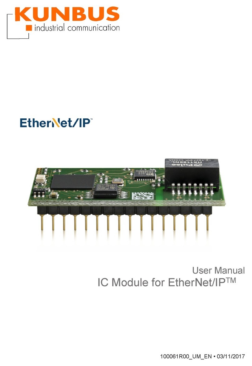
Kunbus cRIO PN C Series User manual

cRIO PN-Installation- V0.3/12.05.2017
cRIO PN –C SERIES Module for PROFINET IO Slave
Installation Instructions
V0.3/12.05.2017

h:\dokumente\project\700391_crio_pn\anwenderdoku\installation\version_0.3\crio_pn_e.doc
Revision History
Version
Date
Description
Resp.
V0.3
12.05.2017
Changed to Kunbus corporate Identity
AME
V0.2
10.06.2015
Ambient temperature changed to 0 - +50°C
JK
V0.1
03.02.2011
Initial Version
JK
KUNBUS GmbH
Heerweg 15c
73770 Denkendorf
Phone +49 711 300 20 676
Fax +49 711 300 20 677
Copyright 2017 by KUNBUS GmbH
Business Confidential/KUNBUS Proprietary
This document includes data that shall not be duplicated, used, or disclosed - in whole or in part - for any purpose other than
to evaluate this document. If, however, a contract with a customer is in force, the customer shall have the right to duplicate,
use, or disclose the data to the extent provided in this contract. This restriction does not limit the customer’s right to us e the
data in this document if it can also be obtained from another source without restriction. The data subject to this restriction are
confidential in all pages of this document.

Installation Instructions Contents
cRIO PN-Installation-V0.3/12.05.2017 i
Business Confidential/KUNBUS Proprietary
Contents
1Safety information.........................................................................................................1
2Installation of the Module..............................................................................................2
3LEDs and Connectors................................................................................................... 3
3.1 Position of LEDs and Connectors........................................................................3
3.2 LED's...................................................................................................................4
3.3 Power connector.................................................................................................. 4
4Technical Data..............................................................................................................5
4.1 Use in hazardous locations..................................................................................5
5CE- Conformity Declaration .......................................................................................... 6

Contents Installation Instructions
ii cRIO PN-Installation-V0.3/12.05.2017
KUNBUS
Business Confidential/KUNBUS Proprietary
List of Figures
Figure 1: cRIO PN module.....................................................................................................2
Figure 2: LEDs and connectors..............................................................................................3

Installation Instructions Contents
cRIO PN-Installation-V0.3/12.05.2017 iii
Business Confidential/KUNBUS Proprietary
List of Tables
Table 1: Meaning of the LEDs................................................................................................ 4
Table 2: Power requirements................................................................................................. 4
Table 3: Technical Data.........................................................................................................5

Contents Installation Instructions
iv cRIO PN-Installation-V0.3/12.05.2017
KUNBUS
Business Confidential/KUNBUS Proprietary
Blank page

Installation Instructions Safety information
cRIO PN-Installation-V0.3/12.05.2017 1
Business Confidential/ Proprietary
1 Safety information
WARNING: Disregarding this
warning may result in damage to
equipment and/or serious personal
injury. Only qualified personnel may
start up and operate this device.
According to the safety instructions in
this text, qualified personnel are
persons who are authorized to start
up, to ground, and to mark devices,
systems, and equipment according to
the standards of safety technology.
In addition, these persons must be
familiar with all warning instructions
and maintenance measures in this
text.
WARNING: The cRIO PN is
designed exclusively for PELV
operation according to EN 60950/EN
60204/VDE 0805-1. Only protective
extra-low voltages according to the
defined standards may be used to
supply.
Shielding
The shielding ground of the
connected twisted pair cables is
electrically connected to the female
connector. When connecting
network segments,
avoid ground loops, potential
transfers, and voltage equalization
currents via the braided shield.
i
NOTE: Electrostatic discharge!
The device contains components that
can be damaged or destroyed by
electrostatic discharge. When
handling the device, observe the
necessary safety precautions against
electrostatic discharge (ESD), in
accordance with
EN 61340-5-1 and EN 61340-5-2, as
well as
IEC 61340-5-1 and IEC 61340-5-2.
i
Housing
Only staff authorized by KUNBUS is
permitted to open the housing.

Installation of the Module Installation Instructions
2 cRIO PN-Installation-V0.3/12.05.2017
Business Confidential/ Proprietary
2 Installation of the Module
The cRIO PN module is a PROFINET IO Device module for National Instruments
CompactRIO system. The configuration entirely takes place by means of the delivered
software. Thus, no jumpers or DIP-switch adjustments are necessary.
To mount the module in the CompactRIO system, please proceed as follows:
Switch off the CompactRIO system
Plug the cRIO PN module into slot 1 until it snaps in
Pay attention to a proper adjustment of the board in the guidance (avoid canting!).
Important note: The cRIO PN module requires 1.7 W of power, so you must use it in Slot 1
while leaving Slot 2 empty.
Important note: The cRIO PN module is supported only in CompactRIO reconfigurable
chassis, such as an NI cRIO-911x, and NI Single-Board RIO devices.
Figure 1: cRIO PN module

Installation Instructions LEDs and Connectors
cRIO PN-Installation-V0.3/12.05.2017 3
Business Confidential/ Proprietary
3 LEDs and Connectors
3.1Position of LEDs and Connectors
Figure 2: LEDs and connectors
SPI - Activity LED
PWR - Power indication LED
SF –System Fault LED
BF - PROFINET Fail LED
Port 1 –RJ 45 Profinet IO
Realtime switch Ethernet port 1
Power –Power supply connector (plug
within scope of delivery)
Port 2 –RJ 45 Profinet IO
Realtime switch Ethernet port 2

LEDs and Connectors Installation Instructions
4 cRIO PN-Installation-V0.3/12.05.2017
Business Confidential/ Proprietary
3.2LED's
LED
Colour
State
Function
PWR
Green
OFF
No power supply connected
ON
Power supply connected
SPI
Green
OFF
SPI bus not active
ON
SPI bus active
SF
Red
OFF
No system fault active
ON
System fault active
Possible reasons:
SPI bus failure
PROFINET Alarm active
BF
Red
OFF
PROFINET O.K
ON
PROFINET Bus fail
Possible reasons:
Configuration error
PROFINET controller not active
PROFINET controller gone
PROFINET controller not connected
Table 1: Meaning of the LEDs
3.3Power connector
Parameter
Value
Nominal value
24 Volts DC
Input range
12 –36 Volts DC
Power consumption
1.7 W in Active mode
(Receiving and
Transmitting)
Table 2: Power requirements

Installation Instructions Technical Data
cRIO PN-Installation-V0.3/12.05.2017 5
Business Confidential/ Proprietary
4 Technical Data
Parameter
Value
Functionality
PROFINET IO Device
LLDP supported
SNMP MIB2 Physical Device
Max. 254 bytes input and 254 bytes output data
16 PROFINET IO slots supported
Min. 1 mS cycle time with RT
Min. 250 uS cycle time with IRT
Acyclic communcation Read/Write Record with max.
256 Bytes
Supported alarm types: Process Alarm, Diagnostic
Alarm, Plug Alarm, Pull Alarm
PN IO Conformance classes
NRT, RT, IRT
Processor
ARM 9 at 150 MHz
Memory
32 Mbyte SRAM
4 Mbyte Flash Type Memory
SPI Interface
SPI Slave up to 4 MBit/s
Ethernet interface
2 Port PROFINET IO Realtime switch
Ethernet Connection Format
8-pin RJ45-female connector
Ethernet Connection medium
Twisted pair cable with a conductor cross-section of
0,14 mm²..0,22 mm²
Ethernet Cable impedance
100 Ω
Ethernet Transmission speed
100 MBit/s
Ethernet max. network
segment expansion
100 m
Ethernet Function
100 Base-T(X)
Power Requirements
1.7 W Active Mode (Transmitting and Receiving)
Storage Temperature Range
-40 °C –+85 °C
Ambient Temperature Range
0 °C –+50 °C
Table 3: Technical Data
4.1Use in hazardous locations
The module is only suitable for use in nonhazardous locations.
PROFINET IO with 100 MBit/s may not be used in hazardous locations.

CE- Conformity Declaration Installation Instructions
6 cRIO PN-Installation-V0.3/12.05.2017
Business Confidential/ Proprietary
5 CE- Conformity Declaration

Installation Instructions CE- Conformity Declaration
cRIO PN-Installation-V0.3/12.05.2017 7
Business Confidential/ Proprietary

CE- Conformity Declaration Installation Instructions
8 cRIO PN-Installation-V0.3/12.05.2017
Business Confidential/ Proprietary

© 2018 National Instruments. All rights reserved.
377815A-01 Sep18
Information is subject to change without notice. Refer to the NI Trademarks and Logo Guidelines at ni.com/trademarks for more information
on NI trademarks. Other product and company names mentioned herein are trademarks or trade names of their respective companies. For patents
covering NI products/technology, refer to the appropriate location: Help»Patents in your software, the patents.txt file on your media, or the
National Instruments Patents Notice at ni.com/patents. You can find information about end-user license agreements (EULAs) and third-party
legal notices in the readme file for your NI product. Refer to the Export Compliance Information at ni.com/legal/export-compliance
for the NI global trade compliance policy and how to obtain relevant HTS codes, ECCNs, and other import/export data. NI MAKES NO EXPRESS OR
IMPLIED WARRANTIES AS TO THE ACCURACY OF THE INFORMATION CONTAINED HEREIN AND SHALL NOT BE LIABLE FOR ANY ERRORS. U.S.
Government Customers: The data contained in this manual was developed at private expense and is subject to the applicable limited rights and
restricted data rights as set forth in FAR 52.227-14, DFAR 252.227-7014, and DFAR 252.227-7015.
Table of contents
Other Kunbus Control Unit manuals
Popular Control Unit manuals by other brands

Continental Refrigerator
Continental Refrigerator FE3NA0031 user manual

LEYBOLD
LEYBOLD ISO-KF Series operating manual

White Rodgers
White Rodgers 50A55-285 installation instructions

AVX
AVX ethertronics ETH-LORA-M-AX-01 Reference manual

Pilz
Pilz PNOZ mc5.1p operating manual

Silicon Laboratories
Silicon Laboratories Gecko MGM210P manual

Texas Instruments
Texas Instruments bq77915EVM-014 user guide

MANN+HUMMEL
MANN+HUMMEL MICRODYN MD020CP2N user manual

Sprint Electric
Sprint Electric 400i product manual

SMC Networks
SMC Networks AV2000 manual

Siemens
Siemens FT2018-U1 installation instructions

Texas Instruments
Texas Instruments TAS6424R-Q1 user guide