User's Guide
TAS6424R-Q1 Evaluation Module
ABSTRACT
This manual describes the operations of the TAS6424R-Q1 EVM. The TAS6424R-Q1 EVM is a stand-alone
EVM. The PurePath™ Control Console 3 GUI (PPC3) is used to initialize and operate the EVM. The main topics
of this document are:
• Hardware implementation and descriptions
• Software implementation and descriptions
• TAS6424R-Q1 EVM operations (hardware and software)
Required equipment and accessories:
1. TAS6424R-Q1 EVM
2. USB A male to micro B male cable
3. Power Supply Unit (PSU) up to 26.4 V, > 6 A capable, if J12 is removed and 12 V is provided.
If J12 is in, limit the input voltage to 18 V.
4. 1-4 resistive loads or speaker loads
5. 2-6 pair of wires stripped both ends
6. 2-mm slotted screwdriver
7. Optical audio source (optional)
8. Optical SPDIF cable (optional)
9. Desktop or laptop PC with Microsoft® Windows® 7 operating system
Table of Contents
1 Hardware Overview................................................................................................................................................................ 3
1.1 TAS6424R-Q1 Evaluation Module Description.................................................................................................................. 3
2 Software Overview..................................................................................................................................................................5
2.1 PurePath Console 3 (PPC3) Access and Description........................................................................................................5
2.2 PurePath Console 3 – TAS6424E EVM Home Window.....................................................................................................7
2.3 PurePath Console 3 – TAS6424E EVM Register Map Window.........................................................................................8
2.4 PurePath Console 3 – TAS6424E EVM Monitor and Control Window...............................................................................8
2.5 TAS6424R-Q1 EVM Start-Up Procedure........................................................................................................................... 9
3 Schematic, Board Layouts, and Bill of Materials...............................................................................................................16
3.1 TAS6424R-Q1 EVM Schematic....................................................................................................................................... 17
3.2 TAS6424R-Q1 EVM Layouts............................................................................................................................................21
3.3 Bill of Materials.................................................................................................................................................................22
4 Revision History................................................................................................................................................................... 28
List of Figures
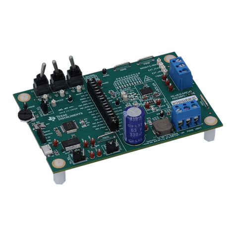
Figure 1-1. TAS6424R-Q1 EVM.................................................................................................................................................. 3
Figure 1-2. EVM Block Diagram.................................................................................................................................................. 4
Figure 2-1. PPC3 Download Window.......................................................................................................................................... 5
Figure 2-2. PPC3 Window........................................................................................................................................................... 6
Figure 2-3. Available Apps Window.............................................................................................................................................6
Figure 2-4. PPC3 Window........................................................................................................................................................... 7
Figure 2-5. TAS6424E EVM Home Window................................................................................................................................ 7
Figure 2-6. TAS6424E EVM Register Map Window.................................................................................................................... 8
Figure 2-7. TAS6424E EVM Device Monitor and Control Window.............................................................................................. 8
Figure 2-8. TAS6424R-Q1 EVM Connection............................................................................................................................... 9
Figure 2-9. Device Monitor and Control Window....................................................................................................................... 10
Figure 2-10. Global Control Section.......................................................................................................................................... 10
www.ti.com Table of Contents
SLOU563A – APRIL 2023 – REVISED SEPTEMBER 2023
Submit Document Feedback
TAS6424R-Q1 Evaluation Module 1
Copyright © 2023 Texas Instruments Incorporated
