nilan CTS602I HMI User manual

INSTALLATION INSTRUCTIONS
CTS602I HMI BY NILAN
VPM 120-560 (English)
Version 3.00 - 04.10.2019

TABLE OF CONTENTS
Safety
Power supply................................................................................................................................................................................................................................................................... 4
Pressure-bearing equipment........................................................................................................................................................................................................................ 4
Disposal............................................................................................................................................................................................................................................................................................. 4
Heat pump.......................................................................................................................................................................................................................................................................... 4
General information
Introduction.................................................................................................................................................................................................................................................................................. 5
General information prior to installation.........................................................................................................................................................................................5
Disclaimer........................................................................................................................................................................................................................................................................... 5
Symbol explanation..................................................................................................................................................................................................................................................5
Supervision of application................................................................................................................................................................................................................................5
Type plate........................................................................................................................................................................................................................................................................... 6
Warnings and rules................................................................................................................................................................................................................................................................7
Not areas of application......................................................................................................................................................................................................................................7
No duct connection................................................................................................................................................................................................................................................... 7
Opening the unit...........................................................................................................................................................................................................................................................7
Unit in pause mode....................................................................................................................................................................................................................................................7
Unit type........................................................................................................................................................................................................................................................................................... 8
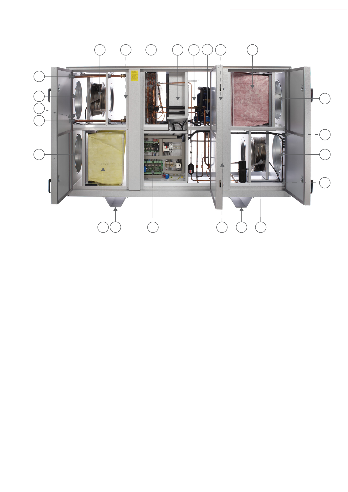
Product description..................................................................................................................................................................................................................................................8
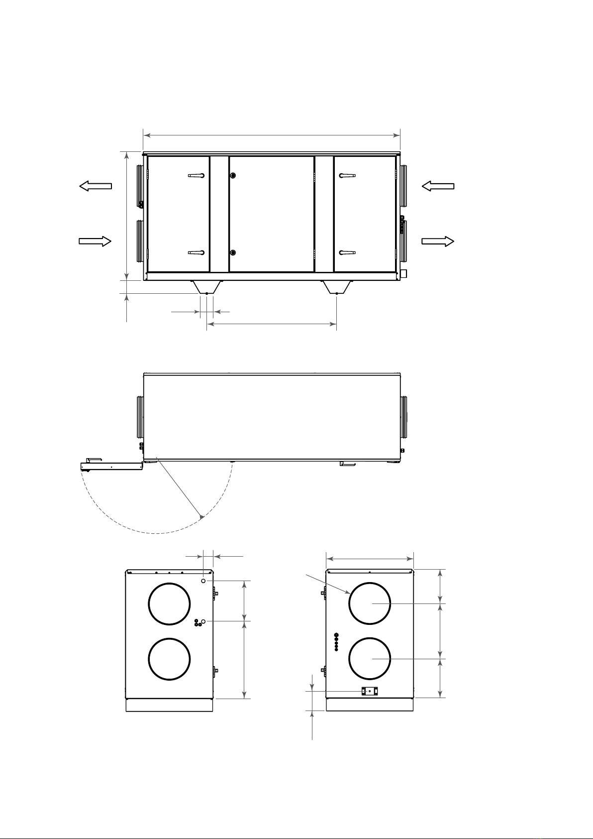
Dimensional drawing VPM 120................................................................................................................................................................................................................10
Dimensional drawing VPM 240................................................................................................................................................................................................................11
Dimensional drawing VPM 360................................................................................................................................................................................................................12
Dimensional drawing VPM 480/560..................................................................................................................................................................................................13
Location of vibration dampers.................................................................................................................................................................................................................14
Functional diagram VPM 120-560.......................................................................................................................................................................................................15
Accessories................................................................................................................................................................................................................................................................................16
Handle with lock cylinder............................................................................................................................................................................................................................... 16
VTZ Compressor......................................................................................................................................................................................................................................................16
Shut-off damper...................................................................................................................................................................................................................................................... 16
Water after-heating element.................................................................................................................................................................................................................... 16
Electrical after-heating element........................................................................................................................................................................................................... 16
Filter monitoring - Pressure transmitter..................................................................................................................................................................................... 17
Humidity control...................................................................................................................................................................................................................................................... 17
Heating Cable.............................................................................................................................................................................................................................................................. 17
Water trap with ball.............................................................................................................................................................................................................................................. 17
Vibration absorbers.............................................................................................................................................................................................................................................17
Pressure control...................................................................................................................................................................................................................................................... 17
CO2 sensor..................................................................................................................................................................................................................................................................... 18
Top cover......................................................................................................................................................................................................................................................................... 18
Installation
Handling.........................................................................................................................................................................................................................................................................................19
Unpacking........................................................................................................................................................................................................................................................................19
Transport after unpacking........................................................................................................................................................................................................................... 19
Installation..................................................................................................................................................................................................................................................................................20
Positioning the unit............................................................................................................................................................................................................................................... 20
Placement and installation of units.................................................................................................................................................................................................... 21
Outdoor mounting.................................................................................................................................................................................................................................................. 21
Electrical installation
Electrical connections....................................................................................................................................................................................................................................................22
Safety.................................................................................................................................................................................................................................................................................. 22
Connections overview....................................................................................................................................................................................................................................... 22
Electrical connection of the unit.........................................................................................................................................................................................................................23
Power supply................................................................................................................................................................................................................................................................23
Unit..........................................................................................................................................................................................................................................................................................23
2

Control panel............................................................................................................................................................................................................................................................................24
CTS602i HMI Touch...............................................................................................................................................................................................................................................24
Wall bracket.................................................................................................................................................................................................................................................................. 25
Electrical connection of accessories............................................................................................................................................................................................................. 26
Connection to user selection and modbus.................................................................................................................................................................................. 26
Water after-heating element (accessory).................................................................................................................................................................................. 27
Electrical after-heating element (accessory)......................................................................................................................................................................... 28
Plumbing installation
Condensate drain................................................................................................................................................................................................................................................................29
Important information...................................................................................................................................................................................................................................... 29
Connecting condensate drain................................................................................................................................................................................................................... 29
Plumbing connections - accessories.............................................................................................................................................................................................................. 30
Water trap with ball (option).......................................................................................................................................................................................................................30
Water after-heating element (accessory).................................................................................................................................................................................. 31
Ventilation installation
Duct system.............................................................................................................................................................................................................................................................................. 35
Legislation...................................................................................................................................................................................................................................................................... 35
Duct connections.....................................................................................................................................................................................................................................................35
Balancing...................................................................................................................................................................................................................................................................................... 35
Important information...................................................................................................................................................................................................................................... 35
Curves for airflow measurement......................................................................................................................................................................................................................36
VPM 120............................................................................................................................................................................................................................................................................36
VPM 240............................................................................................................................................................................................................................................................................36
VPM 360............................................................................................................................................................................................................................................................................37
VPM 480............................................................................................................................................................................................................................................................................37
VPM 560............................................................................................................................................................................................................................................................................38
Maintenance and cleaning
Important information...................................................................................................................................................................................................................................... 39
Maintenance.............................................................................................................................................................................................................................................................................39
Maintenance scheme..........................................................................................................................................................................................................................................39
Replacement of filters.......................................................................................................................................................................................................................................40
Cleaning......................................................................................................................................................................................................................................................................................... 40
Cleaning the unit...................................................................................................................................................................................................................................................... 40
Ordering spare parts
Filtre VPM 120........................................................................................................................................................................................................................................................... 41
Filtre VPM 240........................................................................................................................................................................................................................................................... 41
Filtre VPM 360........................................................................................................................................................................................................................................................... 41
Filtre VPM 480-560..............................................................................................................................................................................................................................................41
VPM 120-560 (English) BY NILAN
3

Safety
Power supply
CAUTION
Always disconnect the power supply to the unit if an error occurs that cannot be rectified via
the control panel.
CAUTION
If an error occurs on electrically conductive parts of the unit, always contact an authorised
electrician to rectify the error.
CAUTION
Always disconnect the power supply to the unit before opening the unit doors, for instance for
installation, inspection, cleaning and filter change.
Pressure-bearing equipment
CAUTION
Take great care when handling as well as disposal of heatpipe and cooling circuit elements as
these have a pressure of up to 50 bar which can cause personal injury in case of breakage.
Disposal
Heat pump
Concerning disposal of units with heat pumps, it is important to contact the local
authorities for information about correct handling of these. The heat pump
contains the refrigerant 407c, which is harmful to the environment if not handled
properly.
4

General information
Introduction
General information prior to installation
The following documents are supplied with the unit:
• Installation instructions
• Software instructions
• User manual
• Wiring diagram
• Test report
Instructions can be downloaded from Nilan’s website: https://www.nilan.dk/en-gb/frontpage/
download
If you have questions regarding installation of the unit after having read the instructions, contact your
nearest dealer of Nilan products. You can find Nilan dealers on www.nilan.dk/en-gb/frontpage/
download/dealers.
The purpose of these instructions is to advice the installer on correct installation and maintenance of
the unit.
ATTENTION
In order to avoid discoloration of the plate parts, the protective foil into which the unit is
packaged must be removed immediately after delivery. The discoloration is caused by a
chemical reaction which is triggered by moisture between the foil and the galvanized plate.
Then cover the unit with tarpaulin to protect it.
The unit is delivered fully tested and ready for operation.
Disclaimer
In order to achieve proper operation with the unit, as well as the safety of persons and equipment, the
instructions must be followed. Nilan A / S disclaims any responsibility for any damage resulting from
the use of the unit and / or accessories in violation of the directions and instructions of this manual.
Symbol explanation
CAUTION
Violation of directions indicated by a warning symbol is associated with a life hazard.
ATTENTION
Violation of instructions specified by ATTENTION is associated with a risk of personal injury or
damage to property.
Supervision of application
This guide applies to VPM ventilation and heat recovery units, hereafter referred to as units. See the
Accessories section for information on included accessories and additional equipment.
VPM 120-560 (English) BY NILAN
5

Type plate
On the type plate of the unit you can read the
following:
1. type of unit
2. unit order no.
3. the unit's serial no.
Note: When contacting Nilan A/S with questions about the product, always have the type of unit, order
no. and serial no. clear. On the basis of this information, the service department can find all
informations about the relevant unit and thus provide information and answer questions about what
the unit consists of/contains, as well as the software used.
6

Warnings and rules
Not areas of application
CAUTION
The unit must not be used for extraction of chips or where there is a risk of explosive gases.
No duct connection
ATTENTION
If one or more of the spout are not connected to a duct, a protective net with a mesh width of
not more than 20 mm must be mounted on this / these.
Opening the unit
CAUTION
Do not open the service doors until the power switch is turned off and the fans have stopped.
Unit in pause mode
ATTENTION
When a ventilation unit is not in operation, humidity from the rooms may penetrate into the
ducts and create condensation. Condensate water may leak out of the valves and damage
furniture and floors. Condensation may also form inside the unit, which can damage its
electronics and fans.
VPM 120-560 (English) BY NILAN
7

Unit type
Product description
The VPM 120-560 series is a ventilation and heat recovery unit with cooling and heat function specially
developed for commercial construction with an air change requirement of up to 5,600 m³per hour.
A VPM unit removes the "used" moist air from the building and in turn supplies "fresh" temperate air.
The energy in the extract air is recovered and transferred to the supply air via a unique combination of
active (heat pump) and passive (heatpipe) heat recovery. The high efficiency of the VPM series is due
to this unique design, which combines the best of two technologies. This improves efficiency so much
that the efficiency comes close to 100%. This means that the need for supply of heat during the cold
winter months is reduced to a minimum, and significant savings are achieved on the building's energy
consumption and a reduction in CO 2 -emissions. During summer time, the process is reversed so that
the supply air is cooled.
It is possible to select a heat exchanger in the cooling circuit. It makes it possible to utilize the excess
energy or waste energy created by the cooling process, for example heating hot water.
The unit can be controlled and monitored via our CTS602i control or CTS6000 control.
8

Left version:
8
1a
13b
13a
1b
3
6 5
2
11a 9
7
1d
1c
14 4
11b12
10 16
16
15
2
1. Duct connections
a. supply air
b. extract air
c. outdoor air
d. discharge air
2. Electrical connections (located on the side of the unit - in the picture they are behind the door)
3. Extract air filter (standard is ISO ePM10> 50%)
4. Outdoor air filter (ISO ePM10> 50% or ISO ePM1> 70%)
5. Valves for cooling manometer
6. Heatpipe / passive heat exchanger (behind shielding and automatic)
7. Condensate drainage (located on the side of the unit - in the picture it is behind the door)
8. Supply air fan
9. Extract air fan
10. Automatic (inside the electric cabinet)
11. Condensers and evaporators
a. Evaporator / Condenser
b. Condenser/Evaporator
12. After-heating element water / electricity (accessory)
13. Pipe for supply / return to water-heating element
a. Supply
b. Return
14. Compressor frequency converter - only with VTZ compressor (in the picture it is behind the door
and shielding)
15. Compressor
16. Base-feet
VPM 120-560 (English) BY NILAN
9

Dimensional drawing VPM 120
The dimension drawing shown is for a left version.
All measurements are in mm.
1975
990100
1000
100
516
591 312
76 675
152
Ø315
302 424 264
Supply air
Extract air
Outdoor air
Discharge air
10

Dimensional drawing VPM 240
The dimension drawing shown is for a left version.
All measurements are in mm.
750
152
Ø400
365 549 326
719 428
80
2155
1240
100
1200
100
565
Supply air
Extract air
Outdoor air
Discharge air
VPM 120-560 (English) BY NILAN
11

Dimensional drawing VPM 360
The dimension drawing shown is for a left version.
All measurements are in mm.
939
152
Ø500
405 629 366
799 510
125
2255
1400100
1200
100
565
Supply air
Extract air
Outdoor
air
Discharge
air
12

Dimensional drawing VPM 480/560
The dimension drawing shown is for a left version.
All measurements are in mm.
2255
1400100
1240
100
1150
132
500 500
108
140152
600
565
500 500
110
140150
600
Supply air
Extract air
Outdoor air
Discharge air
VPM 120-560 (English) BY NILAN
13

Location of vibration dampers
VPM 120
250kg
Green 100x100x25mm Front and rear
VPM 240
340kg
Brown 100x100x25mm Front and rear
VPM 360
480kg
Brown 100x100x25mm Front and rear
VPM 480/560
610kg/615kg
Brown 100x100x25mm Front and rear
14

Functional diagram VPM 120-560
Heating Cooling:
Connections
1. Outdoor air
2 Supply air
3 Extract air
4: Discharge air
5 Condensate drain
6. Electric- and Water after-heating element
Control
T1: Outdoor air sensor
T2/T7: Supply air sensor
T9: After-heating element frost protection
T5: Condenser sensor
T6: Evaporator sensor
T10: Room sensor
VPM 120-560 (English) BY NILAN
15

Accessories
Handle with lock cylinder
If you wish to be able to lock the service doors of the unit, it is possible to
purchase handles with lock cylinder and key.
VTZ Compressor
VTZ is a frequency controlled compressor that has a stable and constant
regulation. The compressor adjusts the operation according to the cooling or
heating demand, and thus will achieve a high COP value, which means low energy
consumption.
The VTZ compressor can be used with the CTS602i and CTS6000 automatics.
Shut-off damper
Shut-off dampers for external mounting are supplied in sets of 2 pieces. with
associated damper motor.
• For the CTS602i, a 230V damper motor is supplied
• For the CTS6000, a 24V damper motor is supplied
Water after-heating element
With a water after-heating element you can increase the supply air temperature
to the desired level. Water-heater can be built into the system and comes with
the necessary sensors.
The water-heating element is controlled using Danfoss Actuator, which is
connected to the plant.
The unit can also control external heating elements.
Electrical after-heating element
The electric heating element is prepared for mounting internally in the fan unit
VPM and is equipped with a binary power distribution.
16

Filter monitoring - Pressure transmitter
Displays the continuous pressure drop across the filter in the CTS control and
gives alarm when the filter needs to be changed at the final pressure drop preset
in the CTS control.
Humidity control
Humidity control can be ordered in the air handling unit according to the actual
humidity in the extract air - either externally or integrated in the plant.
In the control it is possible to choose either moisture control or CO2 sensor
Heating Cable
A 3 m long self-regulating heating cable can be ordered for frost protection of
the condensate drain.
Water trap with ball
To prevent "false" air from being sucked into the unit via the condensate drain, a
water trap must be established. When there is water in the condensate drain, the
water trap works very well, but in the summer months, when there is no
condensation of the extract air, the water trap will dry out and no longer prevent
"false" air. A Nilan water trap with ball ensures against "false" air throughout the
year.
Can only be used in the suction side of the unit in the VPM system.
Vibration absorbers
Vibration dampers (sylomers) for placement under the unit ensure effective
damping of the vibrations of the unit against the substrate.
Pressure control
The motor for the suction and / or supply fan can be controlled by one or two
pressure transmitters mounted in the suction and / or supply duct.
In the standard version, the pressure transmitters come with 5 m cable, including
power supply.
VPM 120-560 (English) BY NILAN
17

CO2 sensor
With a CO2-sensor installed, the fan speed can be pre-programmed to run at a
higher level when there is high CO2 - level in the extract air. CO2 level can be
programmed.
In the control it is possible to choose either moisture control or CO2 sensor
Top cover
If the unit is to be installed outside, it is possible to order a top cover for
protection against rain and snow.
18

Installation
Handling
Unpacking
The unit comes wrapped in foil. To protect the galvanized sheet metal parts from discoloration,
immediately remove the foil and then cover with a tarpaulin until the system is installed.
Transport after unpacking
Transportation of units when this is to be placed and installed can take place in two general ways:
• Lift under the unit with pallet lifts. VPM units with pre-assembled base can be lifted directly with
pallet lifts. VPM systems without pre-assembled base must stand on pallet when lifting with pallet
lifts.
• Lift with rope / straps on the system. If rope / straps are used, the mutual angle must be greater than
60 °. If, for reasons of space, this cannot be observed, a lifting beams or the like must be used.
Min. 60°
Lifting beams
ATTENTION
Visible transport damages must be reported immediately. Hidden transport damages must be
reported within 7 days. When notifying transport damage, photo documentation must be sent.
In addition, reference is made to Incoterm's 2010 terms of delivery, time limits for complaints,
limitation periods and limitation amounts, etc.
VPM 120-560 (English) BY NILAN
19

Installation
Positioning the unit
ATTENTION
Good clearance in front of the unit is recommended (see table). When positioning the unit, you
should always consider future services and maintenance. It must be easy to replace filters and
it must be possible to replace fans or other components. There must be space for easy cleaning
of the unit. When cleaning the unit, water may run out of cleaning and condensation drains.
There must therefore be space for mounting water locks at condensate drains as well as any.
shut-off taps at cleaning drains.
X and Y = Recommended service distance. Z = Door turning radius.
X
Y
Z
Unit X (in mm) Y (in mm) Z (in mm)
VPM 120 3007 676 516
VPM 240 3285 750 565
VPM 360 3385 900 565
VPM 480 3385 900 565
VPM 560 3385 900 565
ATTENTION
The unit must be level to enable proper drainage from the condensate tray.
ATTENTION
The unit produces little noise and only weak vibrations, but you should still take into account
potential vibrations that can spread from the unit to individual building components. In order to
separate the unit from its foundation, it is therefore recommended that you install vibration
absorbers under the unit. There should be approx. 10 mm distance to other building
components and to permanent fixtures.
20
Other manuals for CTS602I HMI
1
This manual suits for next models
1
Table of contents
Other nilan Control Unit manuals
Popular Control Unit manuals by other brands

Hydrotec
Hydrotec HY-MAG Competition operating instructions

Pentair
Pentair SPEEDEO SB-PF-SPO-003C Installation and user guide

APV
APV DELTA SW4 instruction manual

Samson
Samson 3349 Mounting and operating instructions

SPL
SPL De-Esser 500 Series manual

Leonard
Leonard TM-500A Installation and operating instructions for the installer