Kunz AcrEase C60H User manual

60” FINISH CUT
OWNER’S MANUAL
With Assembly Instructions
For Model: C60H
KUNZ ENGINEERING, INC. / MENDOTA, IL 61342 / PH (815) 539-6954
12/04

ASSEMBLY INSTRUCTIONS
READ THE COMPLETE ASSEMBLY INSTRUCTIONS BEFORE STARTING THE ASSEMBLY.
You should have:
-one mower deck assembly
-two caster assemblies
-two rear axle assemblies
-one ATV tongue assembly
A. ASSEMBLY OF MOWER WHEELS
1. Set the mower deck assembly on wood blocks so that it is suspended off the ground.
2. Install the two caster assemblies in the retainers on the front of the mower deck. See figure 1.
Before securing the caster supports, determine which side of the mower the tongue will be
placed on and install the caster support stop on the tongue side. See Figure 2. Secure with
3/8” x 2-3/4” hex head bolt, lock washer, and nut provided in the retainer areas. Secure
remaining caster support with 3/8” x 2-1/2” hex head bolt, lock washer, and nut provided in the
retainer areas.
Note: The operator controls are on the front of the deck and the discharge chute is on the right
side. (Left and right are determined from looking in the direction of travel.)
Retainer Bolts Right Rear Axle Assy.
Direct Behind Tongue PositionOffset Tongue Position
Screw Pin
Shackle Clevis Tongue
Hitch Pivot – Attach
to either Left or R
Caster Assy.
ight
Right Caster Assy.
Figure 1. Assembly of Mower Wheels and ATV Tongue
1

3. Install the two rear axle assemblies in the retainers on the rear of the mower deck. The tire
should be to the left of the axle support. See figure 1. Secure with 3/8” x 2-1/2” hex head
bolt, lock washer, and nut provided in the retainer areas.
Note: Tighten the four wheel assembly pivot bolts so that the wheel assemblies will not flop
down when the deck is raised off the ground.
Caster Support Stop
Caster Support
Tongue
Figure 2: Installation of Caster Support Stop
B. INSTALLATION OF ATV TONGUE ASSEMBLY
1. The tongue can be installed either on the left or right caster assembly depending on how the
wing mower will be towed. See figure 1. Secure the hitch pivot on the chosen caster
assembly with the 3/8” x 2-1/2” hex head bolt, lock washer, and nut provided.
2. Install the tongue into the hitch pivot and secure by placing a 5/16” wire lock pin on each side
of the hitch pivot.
OPERATIONS AND ADJUSTMENTS
This safety alert symbol is used to indicate safety instructions. Follow
these instructions to avoid personal injury and/or property damage. Read
and follow all instructions in this manual and the included engine manual.
Read all Owners Manuals before using equipment.
Know locations and functions of all controls before operating the mower.
A. ATV TONGUE CONFIGURATIONS
Shut off the engine and allow the mower blades to come to a complete stop before
adjusting the tongue.
2

When attaching the tongue to the back of the tow vehicle, tighten the screw pin
shackle clevis firmly. Property damage or bodily injury may occur if the screw pin
shackle clevis unturns and the wing mower becomes unattached from the tow
vehicle.
The hitching system is designed so that the wing mower can be pulled directly behind a tow
vehicle without a mower deck or as a left or right wing mower when towed behind a tow vehicle
with or without a mower deck.
Note: When pulling the wing mower directly behind, it is most maneuverable when the hitch
pivot is fastened on the left carrier arm. See Figure 1.When pulling the wing mower in
the offset position, it is most maneuverable to have the hitch pivot fastened on the right
carrier arm. See Figure 1.
The tongue is designed to adjust from left to right within the hitch pivot. This allows the wing
mower and tow vehicle, with a mower deck, to have proper overlap. Overlap is more critical in
tight areas where a lot of maneuvering is required. This overlap will eliminate most skips between
the tow vehicle and wing mower. In large open areas the overlap is not as critical and should be
adjusted to the user’s preference.
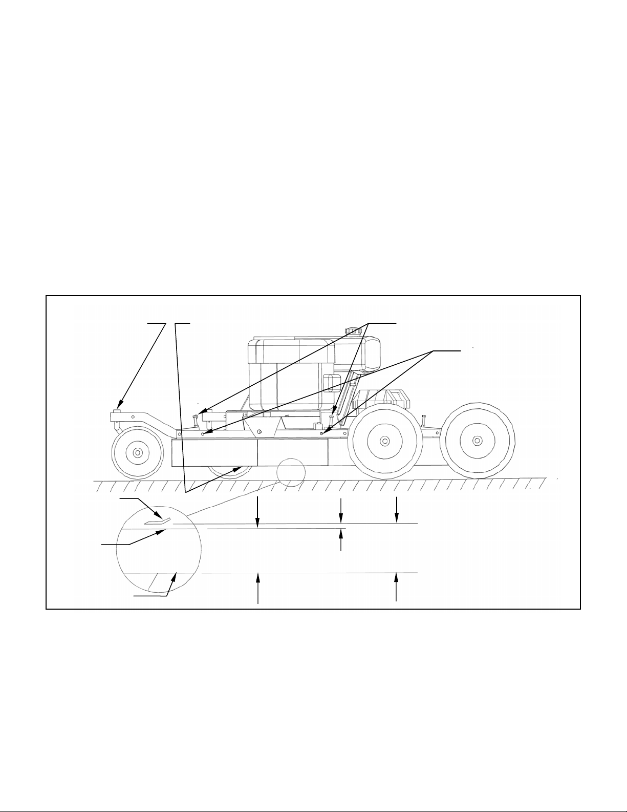
B. ADJUSTING CUTTING HEIGHT
Shut off all engines and allow the mower blades to come to a complete stop on the
wing mowers and on the tow vehicle before adjusting the cutting height.
The cutting height can be adjusted in a range from 1.0" to 4.0". This is accomplished by adjusting
the height adjusting bolts on each of the four corners of the wing mower. See Figure 3. Turn the
bolts clockwise to raise the mower cutting height and counter-clockwise to lower the mower
cutting height.
When more than one mower is used at a time, it is very important to have all the mowers adjusted
as close to the same cutting height as possible to obtain a high quality cutting job.
Adjust the mowers as follows:
1. Pull the mowing unit on to a smooth, level surface.
2. Adjust the tow vehicle mower deck (If applicable) to the desired cutting height and level both
fore and aft and side to side.
3. Measure the distance from the level surface to the mower blade cutting edge on the tow
vehicle.
Shut off tow vehicle engine and allow mower blades to stop completely before
attempting to measure the cutting height.
3

4. Adjust the cutting height on the wing mower so that it cuts at the same height as the tow
vehicle mower. Adjust each corner of the wing mower so that the distance from the smooth
surface to the bottom edge of the deck is equal to the cutting height minus 5/16”. The mower
blade cutting edge is 5/16” above the lower edge of the deck.
Note: To mow in the lower half of the cutting range, set the front caster axles in the bottom
setting and set the anti-scalp wheels in the top hole. To mow in the upper half of the
cutting range (original factory setting), set the front caster axles in the top setting and
set the anti-scalp wheels in the bottom hole.
Note: After the cutting height has been set, be sure to tighten the pivot bolts securely to
eliminate free pivoting of the front casters or rear axles. The front casters and rear
axles should not drop down when the deck is raised off the ground. Snug the four bolts
just beyond the height adjust bolt so the front casters and rear axles can be adjusted up
and down but cannot move from side to side.
Adjust Anti-Scalp Wheels
Under Deck to the Upper o
Lower Cutting Range
r Height Adjustment Bolts
Cuttin
g
Hei
g
ht
Measure the Distance
and Add 5/16” to get
Cutting height
Mower Blade
Lower Edge
of Deck
Adjust for Upper or
Lower Cutting Range
5/16”
Smooth Surface
Snug 4 Bolts to
Eliminate Side
Movement
Figure 3: Adjusting Wing Mower Cutting Height
4

C. STARTING ENGINE
Set parking brake on tow vehicle.
Attach wing mower tongue to tow vehicle.
Do not start wing mower unless it is attached to the tow vehicle.
Set the throttle lever in the choke position to set the choke. (The choke is located beyond the
full throttle detent position.)
Start engine and move throttle toward slow position to disengage choke. The mower blades
clutch will engage as the engine comes up to speed. The mower blades clutch engages at
1850 RPM.
Slow engine speed to idle to allow engine to warm up. This will probably allow the mower blade
clutch to fully disengage.
Adjust engine speed toward fast to fully engage the mower blade clutch. (The full throttle is
located at the first detent position on the throttle control.)
Clutch overheating or failure may occur if engine is not run at full speed in heavy
load conditions.
The engine full speed setting with mower blades running is 3350 RPM.
D. SHUTTING OFF WING MOWER
Shift to neutral, disengage power to the mower deck, and set the parking brake
before dismounting the tow vehicle.
Set the throttle to slow so the mower blades clutch will disengage.
Allow engine to cool down for a short time before moving the throttle control
to the stop position.
E. MOWER OPERATION
Clean or replace any safety signs that are not readable or damaged.
Remove all objects from the work area that might be picked up and thrown by the
blades.
Do not mow when children and others are around.
Do not fill fuel tank while engine is running or hot.
5

Keep all safety shields and deflectors in place during operation.
Remove grass build up from under safety shields before each use. Do not remove
safety shields while engine is running. Dry grass build up around belts and sheaves
can cause fires.
Shut off engine before disconnecting the wing mower from the tow vehicle or
attempting to move the wing mower by hand.
Never carry children or passengers.
Do not allow children to operate this machine.
Slow down and watch the ends of the wing mowers when making turns so objects
are not struck and/or run over.
Depending on the number of wing mowers being towed, it is usually more efficient to mow the
large areas first with the full system. Once the large areas are completed, mowers can be
dropped off to mow narrower areas.
Look down, to the sides, and behind before and while backing to avoid backing over
something or someone. Care should also be taken while backing so that the wing
mower or mowers do not jackknife and damage hitches.
Backing up with one wing mower is easy. Backing becomes a greater challenge as additional
wing mowers are towed. Avoid backing up by planning ahead. Make loops instead of backing.
Stop the mower blades on both the tow vehicle and all wing mowers if the tow
vehicle becomes stuck or stops going forward because of loss of traction. Shut off
the engines on the wing mowers before attempting to push or pull the tow vehicle.
Do not turn too sharply when the wing mowers are pulled in tandem or pulled behind
a zero turn mower. Sharp turns can force the mowers into each other causing
damage to the hitches.
Listen to the wing mower engines while mowing. The engines should run free and not work too
hard. Working the engine too hard will cause overheating and premature failure.
Do not allow material to build up on the air inlet to the engine cooling system. If the wing
mowers are towed with one on the left and one on the right side, there will be a lot of material
blowing around the right wing mower engine. Special care should be taken to make sure the
engine is getting enough inlet air. Do not allow the engine cooling fins under the shroud to be
blocked. Air flow over the engine will be restricted causing the engine to overheat.
6

Mowing to fast in very heavy, long grass can cause the wing mower engine to pull down and
disengage the blade clutch. The engine can then start to accelerate again while slipping the
clutch. Small amounts of clutch slippage for a few seconds will not cause damage. If the clutch
is allowed to slip for longer periods, it will overheat and could be damaged. Watch the discharge
chute; if material is not being discharged, then the clutch is slipping. In normal conditions, clutch
slippage will not be a problem. In most cases the clutch can be repaired by replacing the clutch
springs and clutch bearing.
If the mower blades are allowed to stall out (stop turning) at engine speeds above
the clutch engagement speed, this will cause the clutch to slip. If the clutch is
allowed to slip for more than five minutes, the clutch will get red hot and could cause
the drive belt to start burning.
F. DRIVE BELT REMOVAL AND TENSION (Refer to Figure #4)
Shut off engine and allow mower blades to stop turning before making any
adjustments or repairs.
Front
Engine
Initial Spring Length 15/16”
Running Spring Length 1-1/8” to 1-1/4”
Figure 4: Belt Pattern and Spring Adjustment
Remove the safety shields.
Loosen the nuts on the spring-loaded idler; adjust the nut until the belt can be slipped off the
idler and drive sheaves.
Slip the belt down under the drive sheave and off the blade spindle sheaves.
7

Install the new belt as follows:
Adjust the spring-loaded idler springs to a compressed length of 15/16” initially for a few hours
until the belts run in; then adjust the spring to 1-1/8” to 1-1/4” compressed length.
G. MOWER BLADE REMOVAL, BALANCING & INSTALLATION
Sharp blades can cause bodily injury if not handled properly.
When removing the blade, it is recommended that a block of wood be placed between the blade
and the underside of the mower deck. This will allow the removal of the blade without the need to
hold the blade by hand.
Always balance the mower blades each time they are sharpened.
Out of balance mower blades cause excess vibrations which lead to premature bearing failures,
bolts coming loose, and overall deterioration of the wing mowers.
Always properly tighten the blade bolts to the specified torque. Failure to do so can
lead to unwanted loosening of the blade and damage to the blade holding saddle.
The Model C60H uses the Kunz Engineering Part # (202136) blade bolt. This particular hex head
bolt is a 1/2” – 20NF x 1.00” long, grade 5 and it’s proper torque is 85 ft-lbs.
To ease in the blade installation process, use the same block of wood and method used during
the removal of the blades.
H. LUBRICATION
There are up to six lubrication points on the wing mower -- one spring-loaded idler pivot, two
caster wheel pivots, and three blade spindles (on models that apply). Lubricate at approximately
10 hr. intervals or more often as required in dusty conditions. Lubricate the blade spindles 2-5
pumps every 50 hours. (The bearings have trash guard seals to hold the seals in place during
lubrication.) Lubricate with a high grade of pressure gun grease.
Note: Do not over grease blade spindles. Blade spindles are initially greased at the factory.
Greasing before 50 hrs. may cause bearing seal damage which will result in premature
bearing failure.
I. TIRE PRESSURE
To reduce wing mower bounce on rough yards, the rear tire pressure can be reduced so they
feel slightly soft (approximately 15 PSI) when they are stepped on.
8

J. TRANSPORTATION OF MOWER
When transporting the mowers between jobs turn off the fuel shut-off valve below the fuel tank.
M. STORAGE
If the mower is stored outside, the engine should be covered to prevent water from getting inside
the engine during heavy rainstorms. See the Engine Manual for additional information.
9

WING MOWER SPECIFICATIONS
Model
C60H
ENGINE:
Engine Make Honda
Engine Model GXV390
Cylinders 1
Cycles 4
Crankshaft Vertical
Engine HP 13
Bore 3.46"
Stroke 2.52"
Displacement 23.7 cu.in.
Oil Capacity 1.2 U.S. qts.
Crankshaft Dia. 1"
Key Slot 1/4"
Crankshaft Length 3.12"
Threaded Hole in End of Crankshaft 7/16-20
Engine Mounting Bolts 5/16-18 x 1-1/2" and 5/16"-24 x 1"
Starter Electric
Choke With Throttle Control
MOWER:
Fuel Tank 3-3/4 gal.
Effective Cutting Width 58"
Deck Construction 10 ga. Welded steel
Cutting Height 1" to 4"
Height Adjustment 4 screws
Anti-Scalp Wheels 4 in front, 2 in rear
(3" O.D. x 1-1/4" wide)
Rear Wheels (Fixed) 2 13/500 x 6
(2 ply Turf Pnuematic)
Front Wheels (Caster) 2 9/350 x 4
(Semi Pnuematic)
Blade Dia. 3-20"
Engine Speed, Blades Running 3350 RPM
CLUTCH TYPE Centrifugal
Engagement Speed 1850 RPM
DIMENSIONS
Length 52"
Width 72-1/4"
Height 25"
Weight 380 lbs
TOUCH-UP PAINT COLO
R
Pewter Gray, Krylon #1606
10

ACREASE WING MOWER PARTS MODEL C60H
Item Part # Description Quantity
1 202135 Hex Head Bolt, 3/8" x 3" Fully Threaded 4
2 204000 Shoulder Bolt, 1/2" x 1-5/8" Shoulder Length 6
3 222005 Worm Drive Hose Clamp (7-7/8" to 9-1/8" Clamping Dia. 2
4 225000 Compression Spring, 1-1/2"L x 1-3/32" O.D. x .135" Wire dia. 1
5 226000 Plastic Wheel, 3" O.D. x 1/2" I.D. x 1-1/4" Wide 6
6 226001 Offset Wheel Assy., 13/500 x 6, 2 Ply Turf 2
7 226002 Centered Wheel Assy., 9/350 x 4, Semi Pneumatic 2
8 238002 "V" Belt, B Section, 127" O.C. Dayco B124 Super II 1
9 241001 Flat Idler, 4" O.D. x 3/8" Hole 2
10 258016 Centrifugal Clutch 1
258017 Clutch Shoe (3) ~
225004 Spring, 1850 RPM Engagement (3) ~
243004 Bearing (1) ~
11 258014 Spindle Assy. 3
900046 Spindle Shaft (1) ~
600088 Sheave Spacer (2" Long) (1) ~
900048 Housing Assy. (With Two Bearings) (1) ~
243003 Bearing (2) ~
600086 Bearing Spacer (1-5/8" Long) (1) ~
241007 Sheave, 5-1/4" (1) ~
12 259001 Offset Mower Blade, 2" Wide, 20" Long, 1/2" Hole 3
13 264001 Ignition Switch 1
14 264003 Hour/Tack Meter 1
15 269009 Throttle Control, 27" 1
16 275002 Warning Decal General 1
16 275003 Danger Decal, Cut Finger 2
16 275007 Warning Decal, Belt Sheild 2
16 275012 Control Panel Decal 1
16 275013 Throttle Control Decal 1
16 275017 Name Decal, AcrEase 2
17 277002 Rubber Grommet 7
18 277010 Fuel Tank, 3.75 Gal. (Plastic) (Use Gas Cap 277013) 1
19 277013 Gas Cap (For Fuel Tank 277010) 1
20 600059 Caster Axle 2
21 600062 Belt Sheild L.H. 1
21 600063 Belt Sheild R.H. (Discharge Side) 1
22 600065 Engine Support Bracket 1
23 600188 Caster Support Stop 1
24 900005 Rear Axle 2
25 900021 Caster Support 2
26 900025 Idler Arm Assy. 1
243000 Bronze Bearing, 1/2"I.D. x 3/4" O.D. x 1-1/2" Long ~
27 900029 Mower Deck 1
28 900049 Battery Box Assy. 1
29 900051 Depth Gage 1
30 900052 Tank Support 1
31 900089 Control Panel 1
11

MODEL C60H
1
2
3
4
5
6
7
8
910
11
12
13
14
15
16
17
18
1
19
20
21
22
23
24
25
31
26
27
30
29
28
12

13
Item Part # Description Quantity
1 216002 Wire Lock Pin .31" X 2.50" 2
2 216009 Screw Pin Shackle Clevis 1
3 900057 Hitch Pivot 1
4 900082 Tongue 1
ATV TONGUE PARTS
PARTS LIST
1
4 2
3

SAFETY SIGNS AND LOCATIONS
275007 –
Warning Decal,
Belt Shield
275003 –
Danger Decal,
Cut Hand & Foot
275002 – Warning Decal,
General
Serial # & Model # Decal
Clean or Replace Any Safety Signs That Are not Readable or Damaged
Replacement decals can be purchased from your local dealer or
Kunz Engineering Inc.
Mendota, IL 61342
(815) 539-6954
14

OPTIONAL EQUIPMENT
A. OPTIONAL LAWN & GARDEN HITCHING
Your mower came equipped with the ATV Tongue. The ATV Tongue is a universal hook-up for all
tow vehicles.
The Lawn & Garden Hitching is a great choice for the operator that chooses to specifically use
either a riding mower or a zero turn radius mower for a tow vehicle. This optional feature is for
those who desire the following increased performance.
Part # 900028
Part # 900013
Part # 900008
Part # 900009
Telescoping Hitch Part # 900028
Short Tongue Part # 900013
•The Lawn and Garden Hitching bolts directly to the existing hitch on any riding lawn mower or
zero turning radius mower.
•Allows for close hitching of the AcrEase and provides an increased range of telescoping in or
out to adjust for the tow vehicles deck width.
•Provides a maneuverable quick response system with maximum stability at high mowing
speeds and on steep banks.
•Allows the option of pulling multiple wing mowers. The following pictures are suggested ways
to pull multiple wing mowers with a tow vehicle that has a mower deck. For a complete
description of the combination of hitches needed, please refer to the Figure 5.
Long Tongue Extension Part # 900008
Left and right wing mower set-up.
Rear Hitch Part # 900009
Tandem wing mower set-up.
15

Listed above are all of the possible configurations of the wing mowers. The
numbers listed below each wing mower correspond to the hitch or combination of
hitches required to complete that possible configuration.
1. Tow Vehicle Hitch (Telescoping Hitch) (Part # 900028)
2. Short Tongue (Part # 900013)
3. Long Tongue Extension (Part # 900008)
4. Rear Hitch Assembly (Part # 900009)
5. ATV Tongue Assembly (Part # 900084) (Standard hitch)
1 & 2
combined
1, 2, & 3
combined
2 & 4
combined
1 & 2
combined
1, 2, & 3
combined
1 & 2 combined
or 5
2 & 3
combined
2 & 4
combined
1, 2, & 3 combined
or 5
1 & 2 combined
or 5
Tow Vehicle with a Mower Deck
Tow Vehicle without a Mower Deck
Figure 5: Hitch configurations
16

B. OPTIONAL FLOATATION KIT
This optional floatation kit features an extra front and back tire that can be bolted in the center
section of the mower deck. This is a great anti-scalp feature that helps to carry the center section
of the mower deck and works well in the following applications:
•Rough, uneven ground where added floatation is needed.
•Hard to reach areas at the water’s edge around ponds.
•Extending over a creek banks edge.
•Steep road banks where added traction is needed.
•Gradual crowned or peaked areas in a lawn.
The front and rear are sold separately.
Rear Floatation Kit (Part # 003902)
Front Floatation Kit (Part # 003904)
17

18

19
Table of contents
Other Kunz Cutter manuals