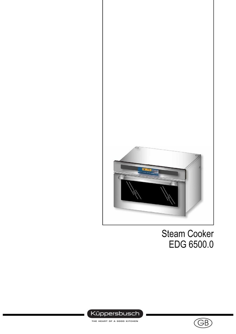
Kuppersbusch EDG 650.0 User manual

GB
Steam Cooker
EDG 650.0

Service Manual: H3-63-01
Responsible: D. Rutz KÜPPERSBUSCH HAUSGERÄTE AG
Tel.: (0209) 401-733 Kundendienst
Fax: (0209) 401-743 Postfach 100 132
Date: 20.07.2000 45801 Gelsenkirchen

Service Manual EDG 650.0 3
For internal use only
Table of contents
1. Introduction ....................................................................................................................4
1.1 Technical Data ......................................................................................................5
1.2 Technical Data ......................................................................................................5
1.3 Specifications .......................................................................................................5
2. Installation ......................................................................................................................6
2.1 Fitting the steam cooker into a built-in unit............................................................6
2.2 Electrical connection ............................................................................................7
3. Features and operation of the EDG 650.0 ...................................................................7
3.1 Operation ..............................................................................................................7
3.2 Control panel ........................................................................................................8
3.3. Control panel ........................................................................................................8
3.4 Information symbols and buzzer ...........................................................................8
3.5 Cooking settings....................................................................................................9
3.6 Setting the timer ....................................................................................................9
4. Cooking settings ............................................................................................................9
4.1 Introduction ...........................................................................................................9
4.2 The cooking process ..........................................................................................10
4.3 Opening the door during cooking ........................................................................11
4.4 Water level sensor...............................................................................................12
4.5 Steamer pan with cover ......................................................................................12
4.6 Cooking compartment and components .............................................................12
5. Testing and measuring ............................................................................................... 13
5.1 Installation ..........................................................................................................13
5.2 Reed switches and LED’s....................................................................................14
6. Repair and maintenance .............................................................................................15
6.1 Removing the upper air duct ..............................................................................15
6.2 Removing the upper air duct ..............................................................................15
6.3 Removing the flap ..............................................................................................15
6.4 Removing the flap ..............................................................................................15
6.5 Removing the lower air duct ...............................................................................16
6.6 Removing the lower air duct ...............................................................................16
6.7 Removing the reed switch card ..........................................................................16
6.8 Removing the flap ..............................................................................................16
6.9 Removing the water reservoir bracket ................................................................16
6.10 Removing the main control card..........................................................................17
6.11 Removing the pump and hoses ..........................................................................17
6.12 Removing the steam generator ..........................................................................17
6.13 Renewing the complete heat barrier mat ...........................................................18
6.14 Removing the flap ..............................................................................................19
6.15 Removing the hinges ..........................................................................................19
6.16 Renewing the interior light ..................................................................................19
7. Fault diagnosis ............................................................................................................ 20
7.1 Type of problem .................................................................................................20
7.2 Fault diagnosis ...................................................................................................20
8. Circuit diagrams ........................................................................................................... 24
4 Service Manual EDG 650.0
For internal use only
1. General
How does steam cooking work?
♦Steam Cooking is a technique for cooking food using pure steam.
♦Steam is distributed evenly throughout the oven. Since the food is initially cooler than the steam, the
steam condenses onto the cooler surface, transferring heat to the food.
♦The steam moves directly onto and around the food, coating it and preventing it from drying out.
♦Steam cooking is a particularly quick and energy-efficient method of cooking, as only a relatively
small amount of water needs to be heated.
What kind of food can be cooked with the steam cooker?
♦Defrosting and cooking of frozen foods.
♦Cooking or steaming.
♦Reheating and keeping food warm.
What is steam cooking especially good at?
♦Preparing appetizing, healthy meals.
♦Preparing light and low-fat meals.
♦Cooking light diet and low calorie foods (for stomach, cholesterol and weight problems).
♦Cooking without supervision.
Which types of food benefit most from steam cooking?
♦Fruit and vegetables.
♦Potatoes, rice and pasta.
♦Meat, fish and seafood.
♦Soups, pies, egg dishes etc.
♦Or, basically, any food that is normally steamed or cooked with boiling water.
What are the benefits of preparing food in this way?
♦Vitamins and minerals are not lost but are largely retained in the food.
♦Taste, colour and texture are also retained and the structure of the food remains intact.
♦There is much less need for salt and spices.
♦Cooking without fat = less calories.
♦Fewer cooking smells - no flavour transfer between foods.
♦Food does not burn or stick to cooking utensils.
♦Cooking
with
oven-to-tableware.
♦Conclusion: Steam cooking helps you prepare healthy meals without any extra work. The steam
cooker is ideal for use in combination with the ökotherm® hob - and oven.

Service Manual EDG 650.0 5
For internal use only
1.1 Specifications
Model EDG 650.0
External dimensions
(H x W x D) 374 mm x 544 mm x 410 mm
Oven capacity 23.5 litres
Net weight 25 kg
Power supply 230V 50 Hz, 1.93 W
Energy consumption 1.18 kWh
Water consumption 0.6 litres
1.2 Features
♦Teflon coated water pipes (no limescale).
♦Removeable door.
♦Electronic regulation with sensor controls and digital display.
♦Interior light.
♦Heated walls for optimum use of energy.
♦Steam generator/ distributor in corrosion-proof aluminium.
♦Cross flow fan for steam extraction.
1.3 Technical data
Cooking 1 hour: 810 W/h
Cooking: 95°C - -110°C (depending on method)
Reheating: 95°C - -110°C (depending on method)
Generator: 1500 W
Heated area: 390 W
Pump: 3 W
Fan: 20 W
Activation thermoelectric device: 4 W
Oven light: 25 W

6 Service Manual EDG 650.0
For internal use only
2. Installation
2.1 Fitting the steam cooker into a built-in unit
If the kitchen unit is not suitably heat resistant, it
must be fitted with heat-shielding material. The
dimensional specifications for installation are shown
in the drawing.
Place the cooker in the housing unit and make sure that it is level.
Connect the appliance to the mains.
Fix in place with the 2 screws. Fixing holes are provided at each side.
Warning!
The vent outlet for the steam is situated between the bottom of the fascia and the top
of the door. This location avoids possible distortion of the kitchen unit.

Service Manual EDG 650.0 7
For internal use only
2.2 Electrical connection
Connection to the mains must be carried out by a qualified electrician.
The steam cooker is fitted with a mains cable and plug. The
appliance must be connected to a standard, earthed
230 V50 Hz wall socket. The wall socket should be located
at the rear of the kitchen unit.
Make sure that the cooker is plugged into the mains before
you fit it into the kitchen unit.
Make sure that the yellow/green earth lead is connected to
the earthing point on the appliance and also to the mains
cable.
The plug must be fitted with a minimum 10 Amp fuse.
3. Features and operation of the EDG 650.0
Control panel
Interior
Reservoir
(no plumbing necessary)
Dish with filter insert
Shelf
Steamer dish attachment
Door
3.1 Operation
1. Place your food in the filter or directly into the glass dish.
2. Place the glass dish on the tray in the cooker.
3. Fill the water tank.
4. Close the door.
5. Adjust the settings on the cooker.
6. Start.

8 Service Manual EDG 650.0
For internal use only
3.2 Control panel
3.3 Display
3.4 Information symbols and buzzer
The oven is fitted with user-friendly information symbols and a warning buzzer.
Message Cause Display
Selecting the cooking method Press the selector button 2 symbols confirm the cooking
method you have selected
Water reservoir level 4 reed switch measured units 1 division on the water
reservoir represents one
quarter
Water reservoir not present or
incorrectly fitted 4 reed switch measured units 1 symbol indicates that the
reservoir is empty
1 alarm buzzer sounds
Door open Door contact Light comes on
1 alarm buzzer sounds
Cooking time Setting via control panel Display in minutes
Cooking method Select the cooking method
using the appropriate button 1 symbol shows a clock
Clock Time display
Start/Stop
Defrost
Cook
Minus Plus
Timer
Time/cooking time
Clock
Timer
Cook
Defrost Water level indicator

Service Manual EDG 650.0 9
For internal use only
3.5 Adjusting the settings on the cooker
1. To select the cooking method, press either the button for cooking or for defrosting.
2. Use the buttons or to set the cooking time.
3. Press .
3.6 Setting the timer
1. Press the button.
2. Use the buttons or to set the cooking time.
3. Press .
4. Use the buttons or to set the cooking time.
5. Press .
4. How the steam cooker works
4.1 General
A removable 1-litre water reservoir (1) is located in the oven. A pump (2) sprays the water through a jet
(3) into the cooking compartment. When this water comes into contact with the heated steam generator,
steam is produced. The oven is first filled with water and the temperature increased to 100 °C. Activation
of the thermoelectric device (6) closes the flap (11) 1.5 minutes after cooking has begun.
When the first phase is reached, steam generation is reduced, in order to compensate for losses and to
keep the oven filled.
To prevent condensate from forming on cold spots, a heat barrier mat, heated to 100°C, (5) is fitted
around the cooking compartment.
When the cooking process has finished, the thermoelectric activator (6) opens a flap through which the
steam is vented with the aid of a fan (7).
The appliance is protected against overheating by an overheat thermostat (8) (170 °C) and control
probe (9).
4 holes in the flap serve to maintain atmospheric pressure inside the oven during the cooking process.
This system is therefore not comparable with a pressure cooker, which cooks under pressure. Its major
benefit lies in the retention of the colour and flavour of the food.

10 Service Manual EDG 650.0
For internal use only
The accessories are not shown in this illustration. The steam cooker is provided with a shelf for cooking
utensils, a dish with a filter and an attachment for the steamer pan.
4.2 The cooking process
Before cooking can commence, 3 preparatory steps have to be taken.
♦Filling the reservoir
♦Selecting the cooking method
♦Setting cooking time
The following description is based on a cooking time of 30 minutes on C
ook
. The process starts right
away.
Time (ms)
Temperature
(7) Fan
(5) Barrier mat
(2) Hydraulic pump
(3) Water inlet tube
(8) Overheat thermostat
(9) Control probe
(4) Steam generator
(6) Thermoactivator (11) Flap
(1)
Reservoir

Service Manual EDG 650.0 11
For internal use only
4.2.1 Phase A: Changing air into steam / increasing the temperature
The first phase takes 10 minutes. The thermoactivator is energized. Approx. 1 minute later, the control
card activates the guide arm to close the flap. The steam generator heats up about 2.5 minutes, before
the pump is activated via the control board (1.2 sec. on, every 12 secs.). This way, 1.65 litres per hour
are supplied to steam generator. The probe adjusts the water supply to the steam generator in relation
to temperature. The nominal operating temperature of the steam generator is between 145 °C and
150 °C. At the end of this phase, the temperature in the oven is at least 100 °C. The actual temperature
varies in response to a number of factors, such as the load ( quantity, type of food) or the air pressure
(weather, height etc.).
4.2.2 Phase B: Maintaining steam and temperature
Every 24 seconds, the pump is switched on for 1 second, supplying the steam generator with 0.5 litres
water per hour. The generator is switched on for 15 seconds every 24 seconds. The length of time the
steam generator stays switched on depends on its temperature. Its nominal operating temperature is
between 127 and 129 °C. This phase continues until 3 minutes before cooking is complete. It enables
losses to be made up and steam to be maintained in the cooking compartment.
4.2.3 Phase C: Removal of steam/ cooling down
The thermoactivator and pump are switched off 3 minutes before the end of the cooking time. No more
steam is produced. The thermoactivator guide arm opens the flap in max. 3 minutes. The fan uses the
Venturi effect to vent steam from the cooking compartment. This prevents steam from escaping when
the door is opened and allows the oven to be cooled down. The temperature of the steam generator is
regulated during the first 1.5 minutes of this phase. The nominal temperature is between 145 and 150 °C.
Only the heat insulator and the fan remain in operation during the last 1.5 minutes of this phase. A buzzer
sounds when it is completed.
4.2.4 Phase D: Keep warm
This phase allows food to be kept warm. Only the steam generator and the fan operate. The temperature
of the steam generator is between 105 and 110 °C. A buzzer sounds until the STOP button is pressed
or the door is opened.
4.3 Opening the door during cooking
If the door is opened while cooking is in progress, the temperature will drop and some of the moisture in
the air will be lost. It is recommended that you keep the door closed at all times to get the best results
from the cooker. Opening the door, which is moved by a connecting rod, actuates the door contact.
♦If the door remains open less than 1.5 minutes, there will be a 2 minute pause while Phase A is
carried out, without the steam generator being heated up.
♦If the door remains open longer than 1.5 minutes, there will be a 5 minute pause while Phase A is
carried out, without the steam generator being heated up.
♦If the door is opened a number of times during cooking, it may take up to 10 minutes to replenish
the steam in the cooker.

12 Service Manual EDG 650.0
For internal use only
4.4 Water level sensor
The water level is detected by a magnet (which is fixed to a float) and 4 reed switches. The magnet and
the float are a fixed part of the reservoir. The 4 reed switches are mounted on a PCB, which is fixed to
the reservoir bracket. The card detects the movement of the magnet through contact with the nearest
reed switch. The water level is thus shown in the display. If the reservoir is empty, an empty water jug
displayed. If the magnet cannot be detected at all, the display shows a missing or a badly fitted jug.
Detection of the water level starts when the reservoir is 1/3 full. If the reservoir is less than 1/3 full,
EMPTY appears on the display.
Cleaning
The accessories can be cleaned in a dishwasher.
4.5 Steamer pan and cover
Limescale should be removed with vinegar. Place a cloth soaked in diluted vinegar on the steamer pan
and leave for a few minutes. Wipe clean with warm water.
4.6 Interior and components
You can clean the interior of the cooker each time you use it. Just wait for the oven to cool down. Rust
can build up beneath these layers of food, due to lack of air circulation.
1. Take out the accessories and remove the water nozzle.
2. Remove any limescale from the nozzle by dipping it in a solution of vinegar.
3. Clean the interior side panels and the steam generator with a soft, damp sponge.
If there is any limescale still on the generator, pour some vinegar onto the affected area and leave
for approx. 15 minutes. Rinse with clean water.
4. Take out the reservoir and dry the cooking compartment.
5. Clean stainless steel surfaces with a proprietary cleaner. Do not use a rough sponge or any
cleaner or scouring powder that contains chlorine.

Service Manual EDG 650.0 13
For internal use only
5. Testing and measuring
5.1 Components
♦Thermoactivator
Undo one of the wires and check for a reading of 980 ohms at the end.
♦Heat barrier!
Undo one of the wires and check for a reading of 46 ohms at the lower surface terminal and 98 ohms
on the upper surface terminal.
♦Pump
Undo one of the wires and check for a reading of approx. 1.5 ohms at the pump terminal.
♦Fan
Undo one of the wires and check for a reading of approx. 117 ohms at the fan terminal.
♦Steam generator
Check the steam generator with a multimeter. The value should be approx. 35 ohms.
♦Steam cooker voltage measurements
Card between 9 and 11 approx. 230V
Pump between 7 and 14 approx. 135V
Steam generator between 4 and 8 approx. 230V
The 1500 W consumption of the steam generator can be checked with an ampere meter. The value
should be approx. 6 Amps.
Door contact
Thermoactivator
Steam generator
Heat barrier mat
Pump
Steam generator
Filter card
Heat barrier mat
Filter card
Oven light
Thermoactivator
Pump
Fan
RELAY
RELAY
TRANS-
M
I
C
R
O
1
2
3
4
5
6
7
8
9
10
11
12
13
14
15
FORMER

14 Service Manual EDG 650.0
For internal use only
5.2 Reed switches and LED’s
A fault with the reed switch card and the display card may be shown at the same time. It is therefore very
important to find out which of these components is actually faulty.
♦Testing the 4 reed switches without a magnetic field: not
infinite
(contact normally opened in the off-position)
♦Testing the 4 reed switches in a magnetic field: infinite
(in operation, the contact is normally closed)
If you do not get a clear-cut reading, you should change the reed switch card.
Once you have confirmed that the reed switch card is working correctly, apply power to the unit, remove
the reservoir and move a magnet from top to bottom near the reed switch on the water reservoir bracket.
Inspection:
♦The water level display is off all the time
♦The empty water level display flashes and the buzzer sounds intermittently when the magnet is not
present.
If you do not get a clear-cut result, you should change the display card.
The fault may lie in the connection between the two cards or in the connector itself. You cannot gain
access to the connector, as it is integrated into the display card.
Magnet
Reservoir
full Reservoir
empty or not present

Service Manual EDG 650.0 15
For internal use only
6. Maintenance and repair
IMPORTANT:
Before starting any repair or maintenance work, disconnect the appliance from the
mains and connect all earth units.
Make sure you have taken all necessary safety precautions before you begin.
Cut off power to the appliance
first of all by removing the fuse at the main fusebox
and then, once the appliance has been removed from its housing unit, by removing the plug from the
wall socket.
Before removing the cooker from its housing unit
- remove all cooking utensils
- take out the reservoir
6.1 Removing the upper air duct
1. Take off the upper protective cap
2. Take out the thermoactivator.
3. Remove the 8 screws on lower air duct.
4. Pull the upper air duct towards the back of the unit and release from the fascia.
6.2 Removing the thermoactivator
1. Remove the upper air duct.
2. Release the two electric wires.
3. Remove the top cover.
6.3 Removing the flap
1. Pull back the upper air duct.
2. Release the flap by sliding it out along the line of the activator.
6.4 Removing the flap seal
1. Remove the upper air duct.
2. Remove the 2 screws on the tangent and the 6 screws on the flap.
3. Withdraw the seal.
Warning: Observe the correct position when refitting and check for a good connection between
the interior and the air duct.

16 Service Manual EDG 650.0
For internal use only
6.5 Removing the upper air duct
1. Remove the upper air duct.
2. Removing the tangent.
3. Remove the 2 screws on the tangent and the 6 screws on the flap.
4. Lift the air duct slightly and release the cable clamp underneath.
6.6 Removing the tangent
1. Remove the upper air duct.
2. Disconnect the two electric wires.
6.7 Removing the reed switch card
1. Unplug the connector.
2. Wrap a piece of cloth around a
screwdriver. Carefully insert the screwdriver between
the card and the reservoir bracket.
3. Gently prise out the card, taking care not to damage it.
4. Repeat these steps with each of the 3 clips until the card is
completely free.
Warning!
If the card is damaged, the reed switches may be affected.
Following removal and reinstallation of the control card, systematically check
that the reed switch is working correctly!
6.8 Removing the water level sensor
1. Release the mounting clip underneath the water level probe.
2. Lift and bend the probe in order to remove it from its mounting.
3. Unplug the connector.
6.9 Removing the water reservoir bracket
1. Take out the reservoir
2. Take out the reed switch card.
3. Unplug the connector.
4. Press down on the 4 flexible retaining feet and remove the bracket.

Service Manual EDG 650.0 17
For internal use only
6.10 Removing the main control card
1. Unplug all the connectors from the main control card.
2. Using a pair of flat-nose pliers, carefully release the six fixing clips and remove the cover from the
unit.
3. Now withdraw the control card from its holder.
6.11 Removing the pump and hoses
6.11.1 Removing the pump – version 1
1. Unplug all connectors.
2. Swing the pump back until it is released from its baseplate.
Warning!
When reinstalling, observe the direction of flow of the pump. (Arrow on the pump
housing on pump version 1).
3. When refitting the pump, make sure that you refit both rubber bushes, to prevent the transmission
of vibration. Ensure that the pump is firmly fixed in position.
6.11.2 Removing the pump – version 2
1. Unplug all connectors.
2. Pull the plastic strap up to release.
Warning!
When reinstalling, observe the direction of flow of the pump. (Thick support on pump
Version 2).
3. To refit, attach the pump to the air duct with the strap. Fit it into its holder.
6.11.3 Removing the water level sensor
The hoses can be released by tugging on them.
6.12 Removing the steam generator
1. Turn the appliance over.
2. Undo the bottom cover.
3. Release the two electric wires.
4. Take out the reservoir
5. Disconnect the cables.

18 Service Manual EDG 650.0
For internal use only
6.13 Renewing the complete barrier mat
1. Remove the main control card. Do not disconnect the cables.
2. Take out the reservoir and its bracket.
3. Remove the upper air duct.
4. Undo the 8 screws on the cooking compartment.
5. Lift the air duct slightly and release the cable clamp
underneath.
6. Release the air duct by moving it to the rear.
7. Next, remove the lamp and the barrier mat.
8. Pull the mat up and towards the front.
9. Then release the right section.
10. Rest the mat on the cross member and then release
the left section.
11. Clean the stainless steel surfaces.
12. Remove the adhesive film from the new mat and
rub to improve adhesion.
Important!
The barrier mat can withstand temperatures of up to 120 °C .
Renewing the rear barrier mat
1. Release the mat.
2. Remove the water pipe.
3. Withdraw the mat.
4. Clean the stainless steel surfaces.
5. Fit the new mat. Remove the adhesive film and rub to improve adhesion.

Service Manual EDG 650.0 19
For internal use only
6.14 Removing the door
1. Open the door to its fullest extent.
2. Insert pins (A) into the holes in the hinges.
3. Push down both round buttons (B) on the door in front
of the hinges. Press down on the hinges.
4. Pull out the door on its sliding rails.
6.15 Removing the hinges
1. Pull out the upper bottom and side panels.
2. With the door closed, pull back the springs.
3. Remove the fixing screws on each hinge and lift off the hinges.
6.16 Renewing the interior light
1. The lamp is located behind a cover at the rear of the interior on the right.
Unscrew the lamp cover and its seal from the holder.
2. If necessary, clean the cover and seal with warm water and soft soap.
3. Unscrew the bulb from its holder and replace with a new one of the same type
(25 W, 220/240 V).
Heat resistant up to 300 °C
Bulb holder: E 14
4. When you screw back the lamp cover, make sure that you fit the seal as well.

20 Service Manual EDG 650.0
For internal use only
7. Fault diagnosis
7.1 Type of problem
Water circulation problem
The main elements in the oven stop working. A buzzer sounds and “E3” appears in the display instead
of the time. 3 minutes after the fault occurs, the fan stops.
Short circuit in probe
The main elements in the oven stop working. A buzzer sounds and “E2” appears in the display instead
of the time.
Open circuit in the power feed to the probe
The main elements in the oven stop working. A buzzer sounds and “E2” appears in the display instead
of the time.
Problem between the reed switch card and the main control card
The main elements in the oven stop working.
Problem between the display control card and the main control card
The main elements in the oven stop working.
7.2 Fault diagnosis utility program
This utility program will check all cables and help you to locate a faulty component. The oven has to be
switched off for at least 3 minutes before you can use the diagnosis utility program.
Start test
Cooker without electric power, without
containers. Switch on cooker
Press the REHEAT
button 5 times
All parts of the display
light up
NO
YES
Diagnosis utility programm not
running display or main card
not working - no door contact
Other manuals for EDG 650.0
1
Table of contents
Other Kuppersbusch Electric Steamer manuals