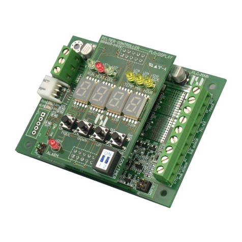
KURAG ELECTRONICS PLC-24V6A User manual

TEC (Peltier) Controller
PLC-24V6A
Instruction Manual
(Rev.2.20)
Kurag Electronics LLC
(1/8)
Thank you for purchasing the TEC (Peltier) Controller PLC-24V6A.
Read these operating instructions carefully to ensure effective use of all the performance
this product as to offer, and then use the product properly.
In particular, please be sure to read "Cautions on use" before use.
fter reading these operating instructions, be sure to store them in a place where they can
be readily consulted whenever necessary.
Technical support and after-sales service
bout support, such as an inquiry about this product, a request for repair, and download of
application software, and after-sale service, it is accepted at the WEB site of our company.
Please contact the address listed below.
KU AG ELECT ONICS WEB site: http://kurag.o.oo7.jp/kurag-el/
Peltier Controller Support: [email protected]

. Cautions on use
✔The use of KE (Kurag Electronics LLC) products with production equipment for the manufacture of
weapons of mass destruction (WMD) or any other weapon is strictly prohibited.
✔The exports of KE products or technology from one country to another are governed by the relevant
security laws and regulation of the countries involved in the transaction. Prior to shipment of KE
product to another country, assure that all local rules governing that export are known and followed.
✔You agree to comply with all applicable international and national laws that apply to the Product,
including Japanese Export Trade Control Order, as well as end-user, end-use, and destination
restrictions issued by Japanese and other governments.
✔We can bear absolutely no responsibility whatsoever for any direct or indirect damage that may
occur due to the use of this product in your applications.
✔This product is to be used with general industrial product, but not designed or manufactured to be
used under such special conditions and environments as nuclear energy control, aerospace,
transportation, medical equipment, various safety equipment or equipment which require high level
reliability that may cause personal death when it is failed. We assume no liability for any direct or
indirect damages that may occur due to applying this product to such equipment or apparatus.
✔If you notice smoke, strange smells or noise coming from the product, cut off the power supply.
Continued use of the product in these conditions will result in fire or electric shock.
✔If a liquid like water or foreign objects like pins and clips which have conductivity adhere to the
product, cut off the power supply immediately. Continued use of the product in these conditions will
result in fire or electric shock.
✔If the product is dropped or strongly shocked or excess power added, cut off the power supply
immediately. Continued use of the product in these conditions will result in fire or electric shock.
✔When electric power is connected to the product, be careful to apply the proper voltage specified in
the product specification. Improper voltage may cause malfunction or destroy the circuit. Moreover,
please do not use it with the power supply voltage exceeding the rated voltage/current of the Peltier
element to be connected. ( same voltage is supplied to the Peltier element.) Please confirm the
polarity of connections. If a mistake made, regarding polarity, it may result in fire or electric shock,
and it may cause malfunction of the product or Peltier element.
✔When you install this product into equipment or wiring the circuit, don’t turn on the power until
work is completed. large current flows into wiring of a power supply or a Peltier element. So
please select the wiring material with suitable diameters.
✔Do not operate at temperatures or humidity, etc. beyond the range of specifications.
✔Please do not use it in a dusty place, the place where direct sun beam hit and the environment where
corrosive gases exist. If a dew condensation is generated, you should not use the product until it dries
completely.
✔Never attempt to perform dismantle or modification. nd when the product breaks down, do not
repair it by yourself. If the product broke down, please consult to our support dept.
✔Failure to heed this instruction may cause in fire, electric shock, personal injury or malfunction.
(2/8)

. Cautions on use (continued)
✔Do not touch directly the electrical components which are mounted on the printed wiring board. nd
please take care not to charge the static electricity to the electrical components.
✔To transport this product, it should be put in the shipping carton, or please put a printed circuit board
into an anti-static bag or a conductive bag, and pack up using suitable shock absorbing material so
that vibration and a shock are not added.
✔Dispose of the product according to all national laws and regulations.
2. General
•TEC (Peltier) controller and driver.
•Maximum drive power is 24V/6 with PWM drive.
•NTC thermistor or PT sensor is suitable for the thermal sensor of this product.
*The sensor is specified by each customer at the time of an order.
The change to another one cannot be accepted after an order received.
•n output for DC fan motor is available.
•Continuous operation mode and timer operation mode.
•Stack-able display board for stand-alone operation.
•The communication port of RS-232 conformity is equipped.
•Free control software and setting software are available from Kurag Electronics WEB site.
3. Contents
•Listed items are included in this product package.
•Please check that these items are included.
Name Main board Display board Main and Display Set
PLC-24V6 Main Board x x
PLC-24V6 Display Board x x
RS-232 Cable x x
Instruction Manual x x x
List of contents
(3/8)

4. Names of parts and functions (Main board)
4
1 2
3
7 6
8 9 5
1. Power Supply Connector
The range of supply voltage is DC 7 to 24V.
2. TEC(Peltier) and temperature sensor terminal
It is a terminal which connects a TEC(Peltier) element and a temperature sensor.
3. DC fan connector
DC fan for TEC(Peltier) element cooling is connect-able. (up to 500 m )
The same voltage as power supply voltage can be outputted for a standard product.
The fixed voltage of 5V or 12V can be outputted for a customized product.
4. 5. Connectors for Display Board
This is a connector which combines a main board with a display board.
6. A connector for a communication cable
n attached RS-232 cable is connected, and it is connected when controlling by a personal
computer.
7. The connector for factory use (no parts may be mounted)
It is a connector for factory production. Nothing should be connected.
8. 9. A terminal for external control (STA T/TIME )
start/stop of temperature control operation and timer operation are controllable by connecting
and switching on and off for these terminals. When you connect and operate a display board,
nothing should be connected with an external control terminal.
10. 11. 12. 13. Status LED lamps
These LED lamps display the product operation status.
* In case of the main and display set, these LED lamps are not mounted.
10. The heater mode is at work: Lights up “HE T” (RED)
11. The cooler mode is at work: Lights up “COOL” (GREEN)
12. The temperature control is at work: Lights up “RUN” (GREEN)
13. Some alarm occurred: Blinks “ L RM” (RED)
(4/8)

5. Names of parts and functions (Display board)
1
3 7
4 8
5 9
10
12 13
11 14
6 15
2
1. 2. Connectors for Main Board
The connectors combine a display board with a main board.
3. 4. 5. Operation status LED lamps
These LED lamps display the product operation status.
3. The temperature control is at work: Lights up “RUN” (GREEN)
4. The heater mode is at work: Lights up “HE T” (RED)
5. The cooler mode is at work: Lights up “COOL” (GREEN)
6. Alarm LED lamp
When alarm occurred, blinks “ L RM” (RED) and the temperature control is stopped
automatically.
7. 8. 9. Display status LED lamps
These LED lamps display the content of 7 segments LED displays. It blinks during a setup and
lights up continuously after decision or during display.
7. Display the temperature: Lights up “TEMP.” (YELLOW)
8. Display the time (unit: minute): Lights up “MIN.” (YELLOW)
9. Display the time (unit: hour): Lights up “HOUR.” (YELLOW)
10. 7 segment LED (4 digit)
This LED displays the temperature or time.
11. MODE key 12. DOWN key 13. UP key 14. SET key
These keys are for setting of temperature or timer operation.
15. Operation switch
Position of switch is upper side ON: Start
Position of switch is lower side OFF: Stop
* Please set it at “OFF” position when the power is supplied or cut.
SW1: Starts/stops the continuous operation.
SW2: Starts/stops the timer operation.
(5/8)

6. Connection
1) Connecting the display unit to the main unit.
* The connection is already established in case of Main and Display set.
Please align the direction of a substrate, and the position of two connectors, and insert straightly.
If the direction is wrong or the position of each connector is shifted, you can not perform the
connection physically. In that case, please do not insert by force.
2) Connecting of Peltier and temperature sensor
This is screw terminal block. Please strip the covering of an electric wire about 5 mm, and insert to
the terminal and keep certain tightening torque using screwdriver.
Pin# Name 3-wire Pt sensor 2-wire Pt sensor NTC thermistor
1 /TH+ Th+
2 B1/TH- B B Th-
3 B2 B Short with pin#2 Open
4 PL+ Please connect the each lead wire of Peltier element respectively as follows.
The surface of Peltier element which should be temperature-controlled is
cooling when a current flows from Pin#4 (PL+) to Pin#5 (PL-).
5PL-
* In case of 3-wire Pt sensor, a current flows into Pin#3 from Pin#1 and Pin#2.
* In case of 2-wire Pt sensor and NTC thermistor, a current flows into Pin#2 from Pin#1.
* Please loosen enough the screw before inserting a wire in a terminal.
3) Connecting of DC fan motor
Suitable connector is 5051-03 (or compatible) of Molex Corp.
Pin# Description
1 GND
2 Vcc (Please connect after checking the rated voltage of the fan motor.)
3 PULSE (if a pulse sensor is equipped) or open (no pulse sensor)
* In case of a standard product, the same voltage as power supply voltage is output to Pin#2 (Vcc).
* In case of a customized product, the fixed voltage of 5V or 12V is output to Pin#2 (Vcc).
4) Connecting of power supply
Suitable connector is VHR-2N (or compatible) of JST Corp.
Please be careful to keep the correct polarity.
Pin# Description
1 GND
2 Power supply (DC 7V to 24V)
5) Connecting of communication cable
When you want to operate this product by communication commands, please connect the attached
communication cable (RS-232).
*Do not connect any cable except for attached communication cable.
(6/8)
Pin#1
Pin#2
Pin#1
Pin#2
Pin#3

7. Operation
Display change by MODE key
Every time when MODE key is pushed, the display of 7 segment LED changes as follows.
Current temperature Push SET key Remaining Time (*)
Push MODE key
Push SET key Target temperature setting
Push MODE key
Push SET key Timer Setting (Unit: minute)
Push MODE key
Push SET key Timer Setting (Unit: hour)
Push MODE key
Operation procedure of continuous mode
1) Pressing the MODE key to change the display to the target temperature setting mode.
(TEMP. LED blinks)
2) Set the desired temperature using UP/DOWN keys.
( fast setting is available by pressing the button continuously.)
* number display will not change by pressing the UP/DOWN keys when the maximum of the preset temperature
range or a minimum are reached.
3) Pressing SET key to complete the target temperature. (Displays current temperature)
4) Slide the ST RT switch of this unit to “ON”. (Start the temperature control)
5) Slide the ST RT switch of this unit to “OFF”. (Stop the temperature control)
* The target temperature is stored in the memory even if the power is turned off.
Operation procedure of timer mode
1) Set the target temperature using UP/DOWN keys as same as continuous mode.
2) Press the MODE key to display the timer setting mode (unit: minute or hour).
(MIN. or HOUR LED blinks)
3) Press the UP/DOWN keys to change the timer setting.
( fast setting is available by pressing the button continuously.)
4) Press the SET key to complete the timer setting. (Displays current temperature)
* The unit of “minute” or “hour” which was set up at the last becomes effective.
5) Slide the timer switch of this unit to “ON”. (Start the timer)
* If a start switch is already “ON”, the timer mode is started from that point.
* If a ST RT switch is turned off, slide both of ST RT switch and TIMER switch to “ON” simultaneously.
6) remaining time of timer is displayed if the SET key is pressed.
(Displays current temperature if the SET key is pressed again)
7) When the timer reached the setup time, the operation is automatically stopped.
* If a TIMER switch is turned off before the end of a timer, temperature control is kept in the continuous mode.
* If a TIMER switch is turned off and turned on again, the timer will start again from the beginning.
* The setting of the timer is stored in the memory even if the power is turned off.
(7/8)
(*)Displays “---- “ at continuous operation mode.

8. Alarm and protect functions
This product has functions of L RM/PROTECTION as follows. Once the L RM is occurred,
the L RM LEDs on the main board and display are blinking and the control of temperature is stopped.
Each function can be set to ON or OFF by the dedicated setting software. Moreover, change of a detection
standard value can be performed about some functions.
Name Default setting Description
Temperature
sensor alarm
ON This alarm is generated by the temperature sensor, un-connecting or wire
disconnection.
Peltier drive
current alarm
ON
Lower: 0.5
Upper: 6.5
This alarm is generated, when the drive current of Peltier element was
lower than its lower limit or was higher than upper limit.
DC fan alarm OFF t the time of DC fan (3 wire type) use with a pulse sensor, if a rotation
pulse is not detected for more than 5 seconds, this alarm will be generated.
Protection for
excess current
when polarity
change
OFF When reversing the drive polarity of a Peltier element, the control
operation will be temporarily suspended to prevent an excess current
flowing into a Peltier element. In this case, an alarm is not generated and
control is resumed automatically.
9. Specifications
Item Value Remarks
Supply voltage DC 7V to 24V
Consumption (Main) 170m (Max) Not include Peltier drive current and DC fan drive current
Consumption (Display) 90m (Max)
Drive voltage / current 24V / 6 (Max) Drive voltage is dependent on power supply voltage. The current is
limited by power supply voltage, and internal resistance and
thermo-electromotive force of Peltier element.
Drive method PWM voltage drive Heat/Cool bipolar drive
Temperature sensor Pt or NTC thermistor 3-wire or 2-wire Pt sensor
Control method Digital PI Control Proportional-integral control
Control temperature range -20°C to +100°C Pt sensor
-10°C to +80°C NTC thermistor
Setting/display resolution 0.1°C
Timer range 0.1min to 999.9min
0.1hour to 720hour
ccuracy of time: +/-1%
Operation
temperature/ humidity
10°C to 40°C
5%RH to 85%RH
No condensation
Storage
temperature/ humidity
-20°C to 60°C
5%RH to 90%RH
No condensation
(8/8)
TEC (Peltier) Controller PLC-24V6A Instruction Manual
Date: July 28, 2017 (Rev.2.20 )
Developer: T.S. Laboratory Corporation
Manufa turer: Kurag Ele troni s LLC URL http://kurag.o.oo7.jp/kurag-el/
Table of contents
Other KURAG ELECTRONICS Controllers manuals
Popular Controllers manuals by other brands

Iris Innovations
Iris Innovations 595 installation manual

Chauvet Professional
Chauvet Professional RDM2go Quick reference guide

Magnum
Magnum ME-RTR owner's manual

BFT
BFT VISTA SEL SW Installation and user manual

Lynxspring
Lynxspring JENEsysONE JO-PC1 Mounting guide

Danfoss
Danfoss ECL Comfort 300 user guide