manuals.online logo
Brands
  1. Home
  2. •
  3. Brands
  4. •
  5. Kurzweil
  6. •
  7. Synthesizer
  8. •
  9. Kurzweil PC88 User manual

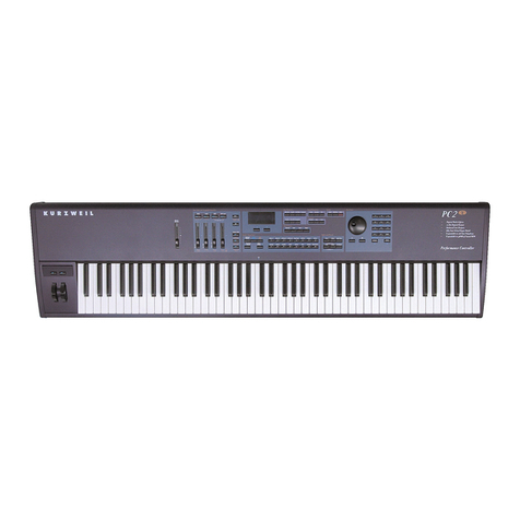
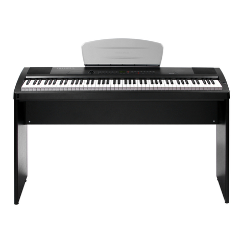
Kurzweil PC88 User manual

PC88
Service
Manual
ee
ee
a
pe
ee
EURZWHIL
Secs
cee
=
SSeS
Tec
Petormence
Coneroter
Pome
eae
naan]
sete
|
/ /
—
€)
se
A)
Fa)
de:
=
too
oe
B
a
—
i
SS
eee
ae
Colo
MULT
AAA
©1995
All
rights
reserved.
Kurzweil
is
a
product
line
of
bead
Chang
Co.;
Kurzweil,
PC88,
and
VGM
are
trademarks
of
Young
Chang
Co.
All
other
products
and
brand
names
are
trademarks
or
registe:
trademarks
of
their
respective
companies.
Product
features
and
specifications
are
subject
to
change
without
notice.
Part
Number:
910276
Rev.
A
INSTRUCTIONS
PERTAINING
TO
A
RISK
OF
FIRE,
ELECTRIC
SHOCK,
OR
INJURY
TO
PERSONS
IMPORTANT
SAFETY
AND
INSTALLATION
INSTRUCTIONS
WARNING
-
When
using
electronic
products,
basic
precautions
should
always
_
be
followed.
Read
all
of
the
Safety
and
Installation
Instructions
before
using
the
product.
Do
not
use
this
product
near
water,
such
as
near
a
bathtub,
sink,
in
a
wet
basement,
near
a
swimming
pool,
or
the
like.
This
product,
in
combination
with
an
amplifier
and
speakers
or
headphones,
may
be
capable
of
producing
sound
levels
that
could
cause
permanent
hearing
loss.
Do
not
operate
for
a
long
period
of
time
at
a
high
volume
level
of
at
a
level
that
is
uncomfortable.
If
you
experience
any
hearing
loss
or
ringing
in
the
ears,
you
should
consult
an
audiologist.
The
product
should
be
located
away
from
heat
sources
such
as
radiators,
heat
registers,
or
other
products
that
produce
heat.
The
product
should
be
connected
to
a
power
supply
only
of
the
type
described
in
the
operating
instructions
or as
marked
on
the
product.
This
product
is
equipped
with
a
polarized
line
plug
(one
blade
wider
than
the
other).
This
is
a
safety
feature.
If
you
are
unable
to
insert
the
plug
into
the
outlet,
contact
an
electrician
to
replace
your
obsolete
outlet.
Do
not
defeat
the
safety
purpose
of
the
plug.
The
product
should
be
serviced
by
qualified
service
personnel
when:
A.
The
plug
has
been
damaged;
or
B.
Objects
have
fallen
upon,
or
liquid
has
been
spilled
into
the
product;
or
C.
The
product
has
been
exposed
to
rain;
or
D.
The
product
does
not
appear
to
be
operating
normally
or
exhibits
a
marked
change
in
performance;
or
E.
The
product
has
been
dropped,
or
the
enciosure
damaged.
Do
not
attempt
to
service
the
product.
All
servicing
should
be
referred
to
qualified
service
personnel.
WARNING
-
Do
not
place
the
power
cord,
or
the
product
in
a
position
where
anyone
could
trip
over,
walk
on,
or
roll
equipment
over
them.
Do
not
allow
the
product
to
rest
on
or
be
installed
over
cords
of
any
type.
Do
not
place
the
power
module
where
it
cannot
receive
cooling
air,
such
as
under
a
rug.
Improper
installations
of
this
type
may
create
the
possibility
of
a
fire
hazard
and/or
personal
injury.
PC88
Service
Manual
ii
RADIO
AND
TELEVISION
INTERFERENCE
WARNING
-
Changes
or
modifications
to
this
instrument
not
expressly
approved
by
Young
Chang
could
void
your
authority
to
operate
the
instrument.
IMPORTANT
-
When
connecting
this
product
to
accessories
and/or
other
equipment
use
only
high
quality
shielded
cables.
NOTE:
This
instrument
has
been
tested
and
found
to
comply
with
the
limits
for
a
Class
B
digital
device,
pursuant
to
Part
15 of
the
FCC
Rules.
These
limits
are
designed
to
provide
reasonable
protection
against
harmful
interference
in
a
residential
installation.
This
instrument
generates,
uses,
and
can
radiate
radio
frequency
energy
and,
if
not
installed
and
used
in
accordance
with
the
instructions,
may
cause
harmful
interference
to
radio
communications.
However,
there
is
no
guarantee
that
interference
will
not
occur
in
a
particular
installation.
If
this
instrument
does
cause
harmful
interference
to
radio
or
television
reception,
which
can
be
determined
by
turning
the
instrument
off
and
on,
the
user
is
encouraged
to
try
to
correct
the
interference
by
one
or
more
of
the
following
measures:
¢
Reorient
or
relocate
the
receiving
antenna.
¢
Increase
the
separation
between
the
instrument
and
the
receiver.
¢
Connect
the
instrument
into
an
outlet
on
a
circuit
other
than
the
one
to
which
the
receiver
is
connected.
¢
If
necessary
consult
your
dealer
or
an
experienced
radio/television
technician
for
additional
suggestions.
NOTICE
This
apparatus
does
not
exceed
the
Class
B
limits
for
radio noise
emissions
from
digital
apparatus
set
out
in
the
Radio
Interference
Regulations
of
the
Canadian
Department
of
Communications.
AVIS
Le
present
appareil
numerique
n’emet
pas
de
bruits
radioelectriques
depassant
les
limites
applicables
aux
appareils
numeriques
de
la
class
B
precrites
dans
le
Reglement
sur
le
brouillage
radioelectrique
edicte
par
le
ministere
des
Communications
du
Canada.
PC88
Service
Manual
iii
Table
of
Contents
Chapter
1,
Basic
Operation
BROAT
PAM
costa
tid
ccedisines
ee
tel
Decal
tat
atau
tlie
ot
So
de
1-1
TOWER
cosciactes
tere
Saati
aera
tos
ecu
eais
eednceesan
eee
ot
eee
1-1
1%,
BG)
eeqvoneeer
ea
ee
erenent
ne
sre
tis
Cnr
ts
et
Omer
ee
rene
Nt
Re
Pee
TEE
1-1
LCD
Contrast
Adjustment
00.00...
cesseeeeeseseeseseseeteseseeneses
1-2
SWAUCH
POCA)
S
Sasesa
te
syu
caticial
eu
neetely
ect
ean
Neoe
glieeemyieese!
1-2
Continuous
Control
Pedals
oo...
cesccsssceccesscesssssscessceeees
1-2
PRUIGIO
QING
seein
its
onem
dl
pete
i
tee
lai
aah
Scena
tetaad
ote
Oran
1-3
Pron
Panel
6a.
ssscehentssiiadcsces
siete
Mass
can,
Sead
caudoes
gaseutit
eis
aa
asnnas
1-3
LCD
and
Cursor
Buttons
.........cccccccssssscecescesceccecescesscesssscaes
1-3
Sound
/Setup
Select
.......cssosesesercccssserssssassssserssecsesssseassseevees
1-4
Internal-VoOiceScs
si:
noe
will
teneie
ici
dads
nea
das
achimte
heed
1-4
MUEDE
S@UUDS
-siesspcasissintstuseeiestsies
AR
bre
hers
heer
lead
etal
a
dnt
1-4
ZONE
PAarAaMeters
ced.
siocdisietenipigidaeha
ddaueaestaceedeiarsemans
banal’
1-5
Zone
Select
and
Assignable
Controllers
.......cccccsccssesesseeeeees
1-5
Dieta
Gey
oz
22.5
san
sstatanured
dunce.
Satara
spelen
aiadedasadaiuata
catuieeessianiaee
1-6
Master
V
Oli
ceca
fienidie:
sissies
cnietees
eaeecloiahebtelawuvaxaaceeeeasipetessavinetigens
1-7
PATMC
Bu
lOi
iis
ee
Siacciechevstaitoeivtitd,
oo
ataicenaiete
sexo
Nebelatoss
1-7
|
5
(fol:
gee
en
ete
emt
ae
ne
ee
ere
eee
te
Conte
aR
ee
eT
1-8
Chapter
2,
Diagnostics
Did
sriostic
Tests
slau
scstlivlns,
tinsel
ioe
ean
sheutina
cede
eee
Sa
atibiaemouees
2-1
DCANNED
LOSES
sii)
thshgie
iene
viwleaiuamse
Seine
sialtvacieaneniak
ume
beediws
2-1
Entering.
Dia
SnOSti
Cs:
5
20s
cacescecuton
ous
ctactayeuaseelanneanaid
2-2
LCD
and
Control
Panel
Buttons
...........cccccessesssssscsescsssssessesens
2-3
Diagnostic:
Tests:
sissies
aig
scsavibsthorteseret
peared
tieatstia
lesser
ccenisiSini:
2-4
WIC
MIO
DG
a2,
sso
oho
tied
aienurenatunt
ni
aacltont
cancel
nadie
2-4
Burnett
MOG
seiavecacs’
cloncetyettec
iterate
hte
ciaceesssernaedontnerder
2-4
DODO
MOG
es
ales
wi
itictetscaletsh
cidade
ues
balms
ieee
2-5
DOU
MOE
ents
cpiscscindetats
Sie
teccerthentarerdilesd
aclu
betas
satel
Aunaeiee
S
2-6
Description
of
Tests7
fei
ncs
tu
astincwrciniealiesienaea
ne
larcihains
2-7
CPU
Test
aictccrcars-
usage
a
ssn
gh
aiuan
cade
sansudadiessavaniten
eeveiareatan
2-7
Program.
ROM,
Test
siscstensiscsscennntu
ea
dsaecet
thes
tac
smauioctactaines
2-7
TT
CS
Uo
tas
pli
oeser
hates
oie
cts
lowe
tata
aces
Tea
te
2-7
IN
VIR
AINE
TeS0
caitatsicccuecttensts
tediens
casts
tatacttod
cated
sdailbdesct
calcd
2-8
MIDIUART.
Test
csccvesocecueae.
oi
sata
asancandneeeuadads
thexiagee
2-8
DCAMCr:
LOSE
eat
p
ceded
talaga
ae
nner
tn
eaters
2-9
Parallel
I/O
(PI/O)
Test
........cccccscscssssscssseseessssessseesestseesscsees
2-9
PC88
Service
Manual
1U
TIM
Ete
POSE
aks
fveere
te
dtvies
coves
eno
eet
ihe
deren
2-9
PIOTIOE
VASE
sxecstcciice
eho
eet
eae
at
ey
ucaieraler
belt
tatuedinetesete
2-10
Sound
ROM:
Vest
vies
cece
ssh
ea
lege
Seanad
cee
tae
badd
2-10
Mate
Test
ciipicscclsececna
bids:
caselatenenenngeriainalstete
tan
dutistasoaines
2-11
Delany
TRAM
Test
2cses
a
tasesstaetetsnnsnjeadnrsen
oataatages
focdoabeneanansna
2-11
LEDs
TeStertac
creed
tur
eevee
i
Ase
ee
2-11
VGM-
Port
TeStéisacicie
tlt
ioresh
vinta
cekeersas
an
eee
2-12
COU
CSE
iy
ait
ctce
eens
sates
toate
aaah
ses
eeecoataen
ek
eet
2-13
SCANTIOE
TCS
US
vesos
cezszcseswiewserraea
dna
teouieaven
tam
svereiereenenesae
2-14
Data
Wiel
citccccce.teecl
tiasaecegedet
oy
fataetoednas
accne
te
ieeeet
seats
2-14
Front
Pariel
Buttons:
«.
csecicccscgescassvenssascatiaaviccsnceadetsseeeenes
2-15
Front
Panel
Suid
ers
ics
ices
ane
een
nae
2-15
Keyboard
wsciestiaisisssenttatetdisnyeaneteceencatiedonilerarteisperseersaneastiaahs
2-16
Mod
Wheels
.....c.ccccscsecsceesseseeeeees
Pastas
eho
et
ch
2-17
Switch
Pedals
wicca
eee
ass
ine
eeaiosiinen
case
2-17
Continuous
Control
Pedals
.............cccccssssscccceeeenseneeeseeee
2-18
Chapter
3,
Disassembly/Assembly
TAtPOC
CHO:
a
esesintsnctei
anh
ancien
atin
ene
en
nines
3-1
EMI
Shields/Enclosure
Support
Wall
.........:ccsccesesesenees
3-2
PIG
UGS
oectecssited
A
veo
ted
daca
cte,
ta
alo
anasepwnants
datesatelpsaeesa
nates
eabtliags
3-2
Assembly
Instructions
siidisca.sectseccore:
ioc
tnaiienian
asain
3-3
BMY
SHEL
AS
ass
ccssen
dacs
ewsctsavscaacutvatisa
gaaleisth
daded
sales
Kec
Synedneawadebotlap
cateves
3-4
PIGUne
D2
ends
etcealerh
par
aidibanlinseatiananieece
el
aaneeiesest
3-4
Opening
the
PC8S
sicsicsdsetecestaeusatrccnscasesetaracaredasensttonneiwbvnayierts
3-5
FUGUES
O23
ates
ssascsvscsesaentnsinclecwanaacscennsles
ties
ee
lghate
soluatacubecoeaitebersnecs
3-5
Removing
the
Top
Cover
Assembly
........cssesecseeeneetees
3-6
Pipire.3
Aoaiiiiae
caigiettneieaariasans
pis
sbbieuastesderandscaalspaasdelnens
3-6
Pig
uire:
3.5
&
Jedsasssventieduv
conti
subitiabancsl
cuceodsi
cies
eeteaeact
ines
nipiete
ates
3-7
PiU
3G
cash
siyasencecstendecesta
stead
sagaadeseaep
nage
ott
eee
qenceana
aeeaeneesiese
3-8
Replacing
the
Top
Cover
.......scssssssssssesssssnsserssscsesseetsenonesnees
3-9
Removing
the
I/O
Board
......cccecseeseesssserseeseeesenesessenenereens
3-10
Replacing
the
[/O
Board
......ccccsssesseseeeeseeesenesssnseesenenenees
3-11
Removing
the
Control
Panel/Switch
Board
...............+4
3-11
Replacing
the
Control
Panel/Switch
Board
...........00+
3-12
Removing
the
LCD
Board
........ccessseeeeseeneeeeeneneereneneenes
3-13
Replacing
the
LCD
Board
.........:ssssssssssenenseneneesseeneesenetsans
3-14
Removing
the
Slider
Board
.........cccscccseseeteteeeeeeeteenenes
3-15
Replacing
the
Slider
Board
.........ccccssseseseeseeeseeeeeeneteneens
3-15
Removing
the
Engine
Board
........ccccceeeseteeeseseeteeneneees
3-16
Replacing
the
Engine
Board
........ccccscsesseeseseeseesseeneneneees
3-16
Removing
the
VGM
Board
.......ccssseeeetsseteneeeneeneneneeneees
3-17
PC88
Service
Manual
v
—
Replacing
the
VGM
Boat...
cesesssesetseererenenseeeneeees
3-17
Enclosure
Support
Wall
wicvsissciicsssccsessssycvosssanuetsveniwas
ese
duedeossataeies
3-18
Openiti¢
the:
PC88
a4
idisitadaniwis
ah
NAGS
wtdetlagols
3-18
BiG
6G:
Daz
ssc
wsiiyesinle
Ruin
donctined
ns
ton
nadia
Niatameera
tiene
3-18
PIG
Ure:
Bi
isis
cheastatat
oantivacicastuanurteter
i
edetecariencndeaccnaean
aes
3-19
Removing
the
Top
Cover
Assembly
...........:scseeseeeeeeeees
3-20
FEL
UID.
9
ase
Mra
css
saya
sedeaiuents
sels
Sho
tn
ernaBRa
indi
seas
hecuee
aaa
3-20
Bip
re
Dil
Oh
secs
cctiee
secs
eats
me)
ieresieliGaataens
hasten
Gieatacs
tote
ba
days
3-21
Pip
Ure
Sal
sss
tev.
wesc
socecnustscvans
taped
sanoidvnetisiyavialancosasotoats
chtamibiecedss
3-22
Replacing
the
Top
Covel
ecsicissvsimaisenovacsnteRapicensdanialaiuanine
3-23
Removing
the
I/O
Board...
ccccscssssssesssssscsessstseeesceseeses
3-24
Replacing
the
I/O
Board
oo...
ceecceeeeeeeeeeeeesensseecessens
3-25
Removing
the
Control
Panel/Switch
Board
...................
3-25
Replacing
the
Control
Panel/Switch
Board
0.0...
3-26
Removing
the
LCD
Board
........cccccesssssesesesseesessnersteeeneees
3-27
Replacing
the
LCD
Board
uo...
ccccessesesseseesssesssesesencerens
3-28
Removing
the
Slider
Board
o.......cececsssesessesceseseeeseeseseees
3-28
Replacing
the
Slider
Board
ws
ssssssssnesseeseeesereeeeenees
3-29
Removing
the
Engine
Board
occ
esscesesecsesseecseeeeeeaes
3-30
Replacing
the
Engine
Board
ou...
cesses
esesesesseeeeseens
3-30.
Removing
the
VGM
Boat
wiwccsescsssssssesesssesessseseasseseeens
3-31
Replacing
the
VGM
Board
ou...
csecsesssesececestsesseneneseenens
3-31
Removing
the
Mod
Wheel
Assembly
.........ccccssssessseseseseeees
3-32
Removing
the
Keyboard
2
sscsisaatenitsh
sinsassauitvetcndiontuietel
sissies
3-33
FU
BUT
1
25
csacsztahciaacisadienl
stars
ateaagsdurey
astentenbia
tee
satatan
tava
iads
3-33
RREMOVW
1g
a
ROY
i
vind
sees
vesietaduhageseseteca
ahsuieacteznse
sanesarsoaluvaustvdeateek
3-35
Pig
Uae
Dud
sashes
shnssseadsnetanscesanenedugatavaniparnonnate
ee
mubeiasnaukabligadiats
3-35
Natural
WHC
IRC
YS
vs
cniit
tui
achdioeel
ototench
personae
sitiosdedhet
ass
3-36
SH
arp
y
BIACK
CYS
sess
eauiticl
siesta
tenets
i
eee
cients
3-36
Replacing
a
Key
sccssesenteihs
tS
ssvsinseh
Se
sanisvtebesdabia
alien
neatesceetgeasedyeact
3-37
Removing
the
Keyboard
Contact
Boards
..0.....ceeseeseeeeeeees
3-38
Removing
the
Treble
Contact
Board.
..........ccccsssseessesesees
3-38
Replacing
the
Treble
Contact
Board
oc
eceeseteeeeereees
3-39
Removing
the
Bass
Contact
Board
........eeseeeereteeerenes
3-39
Replacing
the
Bass
Contact
Board
oo...
cssseeseeeeseseeees
3-39
Removing
the
Keyboard
Contract
Strips
..0.....
cesses
3-40
PIU
301A
scstsaaiasesessddens
sacstoeecciiets
oat
bass
saitiiaiiun
waunpondinens
bine
3-40
Replacing
the
Keyboard
Contact
Strips
.0.....essseeteneeeeee
3-41
Removing
a
Key
Weight
<sscsssssisssecveserssceseunentesdsausconssderadeounels
3-41
PPV
UAY
SS
Vo
aca
s3hd
Boba
a
char
dosaanas
ted
cheahenar
se
seae
aul
aclstacaials
3-42
Replacing
a
Key
Weight
ss
ssceaicinasissciaicauidewiass
3-43
PC88
Service
Manual
vi
Chapter
4,
Troubleshooting
INtFOCUCHOR
ake
see
iae
eed
ace
erent
CUSIOMET'S
SOUPS
saci
iesguddeativeenrineeniarntrdneilntedeenles
tars
DA
VINE
DCLUPS
ated
culver
neck
ties
onnue
eel
ateneoa
meaaie
ae
Surface-Mount
Devices
........ccccccsccesssscesssecessseceesseceesesseeeesseeees
PE88
RESCtS
iscsi
hd
ieetuiis
desactnse
er
cli
Sastre
dana’
FAVA
ROSCOE
ay
cdvsschicdonctandbeslaczaccdsiua
sharpie
tie
ouadidelersonentans
SOL
IRESEE
a
iiasakeiges
sa
vsuescee
caatateea
otha
lus
aan
oon
neaestees
POWeE
PLODlOMIS:
sitecc
chine
heeds
oaado
sedis
eae
assaeses
Front
Panel
Problem
..........:..ccccccccccccesessscsecsesesserssscceceecsceccssteees
AUIGIO
PLODIEINS
wc
sioelewchee.
eeatckeh
ethevee
cas
enssiat
ese
AL
aeeeaaxs
Internal
Sound
Problems
.............cccccccccsssssssscecceaseseecceesessnsessassees
Keyboard
Problems
..........:ccccsseceeseeeees
Stes
iaeiete
tae
tent
4
BAUteLy
savesuviaisostiaissi
dear
choaddsdeduchssobasisnesiinscantevedeectesitnensiinauasenetoe@es
4
Removing/Replacing
the
Battery
...........ccccceeeseeeeenees
4
PEWMIIOLS
idea
sesvesidevibavas
st
duaesttass
urna
dadendiders
Ginnie
mutase
ea
tiuies
4
INLEFCOMME
CE:
Dia
PANY
exesatpsagcseszass
st
ansosbadedeuneopaatangastapianoe
amamneennns
4
Engine
Block
Diag@raimy,
..2.secsedesn
ta
sieeeaniois
enlace
niie
anal
eadeceeaeies
4
Table,
37451
Microcontroller
............cccccccccsccccescscessssccssseeseerseees
4
TOS
POU
Ss
rare
a
hee
yi
stes
cecsse
deo
RGPaae
eae
ives
ates
nea
aan
4
Chapter
5,
Parts
Lists
Tf
BO
ats
4osechasesheresnstsadanecsesunstadvaccay
epdecestis
aaspactaues
eal
aeuachadns
dawaatsos
Main
Control
Panel
Board
..........ccccsssccsstecsssssccesneceessceseseersesaees
Slider
-BOarG
-sesiicduateinstoctaweonaead
wa
eactai
aanceiac
carat
oes
TCD
BOAR
hes
susteastiotiecccessdotease
vet
etinea
sarees
ates
Rise
Sa
viosiadenaiad
ereeneks
Engine
Board:
(DIP)
sistent
cosaasecaltiatesshnandraieandies
Engine
Boatd
(SMD)
ssc.icciscs.
dsc
vctianencesgi
nadia
ieee
hci
yasataes
Wheels
ASSEMBLY
is
cdescsh
sans.
serasdebsiertteassesiatatocustedoresiadienoiaencasisers
Keyboard
Assembly
.i.c.dascsssntiinghisaieaieiadsantianieneiieabeicvases
AIG
situa
cats
ad
Catnters
ree
esau
e
Neuter
tos
etaaint
ar
aueevauceuaCurhiian
anmenatatiee
CaSE/
ENClOSU
FC
ei
ieii
actu
cressaiierictad
asad
totes
Mesa
Filede
tease
teth
eet
Par
W
Al
aco
tess
ws
ccsetuarecdeseadecedsDeacheasildetestuetreassiis
eutiwass
vandern
iadeusus
Miscellaneous:
a2icesii
ction
iabccstal
de
sunicestsestiaandsdhibieiitiade
erent
PC88
Service
Manual
voli
Chapter
6
Schematics
TO
Board
SHOGt
1
iss. tivc
cache
supers
erie:
che
arnc
ees
dial
Sook
viteameet!
6-3
I/O
Board,
Sheet
2
......cccccccsscsscsssscscseccsscsecsesscssesssscssccesesescessusees
6-4
Main
Control
Panel
Board
.0.....ccccccceecessscsecceccessssseesceasseccsssseees
6-5
DOOR
BOA
sii.
Giietced
ax,
crietsn
Latvape
ead
sndototaetincaaeid
seasote
eke
decdoantindss
6-6
Engine
Board,
SHEGt
ai.
tstb
sound
av
uecesd
veer aiva
decile
vsseestiiatblsay
6-7
Engine
Board
Sheet,
2
aiecsscavehciereeteewsarsnnd
lssdcicaationtine
mlaieslane
6-8
Engine:
Board,
SHEGES
sssiscssiteetss
eins
duardessernssanaesmastaiecibasyieetss
6-9
Engine:
Board,
Sheet
4
is
tices
actaciueslosisesauda
asian
tases
6-10
Engine:
Boards
SHOES
cist
casas
oss
Seales
vars
cud
hcng
sdentees
ceatidactseeoadacd
6-11
Engine
Board,
Sheet
6
........scseccscssssssssssscscsssscssssssscsecscescsssseecesers
6-12
VGM
Board,
Sheet
1
.....ccccscccccsceccesceccescsssescescsscsssssscsscssceesseees
6-13
VGM
Board,
Sheet
2
u.....ccccccccscsscsscsscsscsscescescsscessesessesscssssscessees
6-14
VGM
Board,
Sheet
3
o.....ccccecccsscsscsscsscssceccsscescessescsccssessesesssscnenes
6-15
VGM.
Board,
Sheet
4
isiccasica2itocd
apedte
vetted
eine
Nevins
daioneticsce
Sled
6-16
VGM
Board,
SHG6t
5
xsessscsossiicermrceaniuadeesiveddccossom
abcess!
6-17
WReeIS
Boat
esi
jeg
sccdeGucesxtindee
sedakadpapives
naedovcauciieltadtet
wench
ews
ase
6-18
I
PC88
Service
Manual
viti
Young
Chang
Distributors
Contact
the
nearest
Young
Chang
office
listed
below
to
locate
your
local
Young
Chang/
Kurzweil
representative.
Young
Chang
America,
Inc.
13336
Alondra
Boulevard
Cerritos,
CA
90703-2245
Tel:
(310)
926-3200
Fax:
(310)
404-0748
Young
Chang
Akki
Co.
Kang
Nam
P.O.
Box
998
Seoul,
Korea
Tel:
011-82-2-3451-3500
Fax:
011-82-2-3451-3599
Young
Chang
Akki
Co.,
Ltd.,
Europe
Industriering
45
D-4060
Viersen
11
Germany
Tel:
011-49-2162-4491
Fax:
011-49-2162-41744
Young
Chang
Canada
Corp.
395
Cochrane
Drive
Markham,
Ontario
L3R
9R5
Tel:
(905)
513-6240
Fax:
(905)
513-9445
PC88
Service
Manual
ix
~~
Specifications
Physical
.
Height:
¢
Width:
*Length:
eWeight:
Electrical
Voltage
Range:
Frequency
Range:
Input
Voltage:
Power
Consumption:
Environmental
Temperature
(Operating):
Temperature
(Storage):
Relative
Humidity
(Operating
and
Storage):
Audio
Output
Connection:
Impedance:
Output
Level:
Dynamic
Range:
45/16"
(10.95
cm)
14"
(35.6
cm)
545/16"
(137.95
cm)
55
Ibs.
(25
kg)
120
VAC
240
VAC
100-125
Volts
RMS
200-250
Volts
RMS
48-65
Hz
48-65
Hz
9.5
Volts
AC
9.5
Volts
AC
2.0
Amps
max
2.0
Amps
max
40
to
104°
(5
to
40°C)
-13
to
185°F
(-25
to
85°C)
5
to
95%,
non-condensing
2x
1/4"
Mono
Phone
Plug
2K
Ohms
3.5
Volts
RMS
Max,
1
Volt
RMS
Nominal
>103
dB
"A"
Weighted
PC88
Service
Manual
x
Chapter
1
Basic
Operation
The
following
is
a
brief
description
of
the
Kurzweil
PC88's
Front
Panel
controls
and
Rear
Panel
connections.
This
has
been
prepared
for
the
servicer
of
the
instrument
to
give
a
general
idea
of
basic
operation.
To
examine
the
full
capabilities
of
the
Kurzweil
PC88's
functions,
consult
the
PC88
Musician's
Guide.
Rear
Panel
The
Rear
Panel
contains
the
connections
for
power,
MIDI,
audio
pedals.
Power
9.5V-AC
In
MIO!
Select
MIDI
in
MID!
ThrufOut
=
MIDI
Out
Cc
An
P
eo.
L_s]
=!
a
a
a
“e
|
2.0A
Power
The
PC88
uses
an
external
9.5V,
2.0A
~
AC
power
supply.
Power
is
turned
on
by
pressing
the
rocker
switch
into
the
"on"
position
(white
dot
in).
Prior
to
connecting
the
power
supply,
be
sure
the
switch
is
in
the
"off"
position
(white
dot
out).
.
There
is
a
strain
relief
mounted
on
the
rear
panel
so
that
the
wire
from
the
power
supply
can
be
wrapped
around
it
to
prevent
damage
to
the
AC
jack
if
the
the
cord
is
yanked.
Wrap
the
wire
once,
not
too
tightly,
around
the
strain
relief,
before
inserting
the
plug
into
the
socket.
MIDI
There
are
three
MIDI
jacks
on
the
rear
panel,
MIDI
In,
MIDI
Thru/Out
and
MIDI
Out.
PC88
Service
Manual
1-1
Chapter
1
Basic
Operation
Use
the
MIDI
In
to
receive
up
to
16
separate
channels
of
MIDI
data
into
the
PC88.
The
PC88's
MIDI
Out
can
send
up
to
four
channels
simultaneously.
The
MIDI
Thru/Out
has
two
functions.
To
the
left
of
the
MIDI
In
jack
there
is
a
MIDI
Select
switch.
The
MIDI
Select
is
a
slide
switch
which
allows
you
to
select
either
MIDI
Thru
or
Out.
In
the
Thru
position,
it
allows
you
to
send
data
being
received
by
the
PC88
through
to
multiple
MIDI
instruments.
In
the
Out
position,
it
doubles
as
a
second
MIDI
Out
jack
which
allows
you
to
hook
up
multiple
instruments.
LCD
Contrast
Adjustment
Located
between
the
MIDI
and
the
Switch
Pedal
jacks
is.
a
rotary
knob.
Turning
the
knob
adjusts
the
LCD
to
accommodate
different
playing
positions.
Switch
Pedals
There
are
two
jacks
on
the
rear
panel
for
switch
pedals.
The
pedals
should
have
two-conductor
1/4"
plugs.
Either
normally
on
or
normally
off
switches
can
be
used.
They
are
typically
used
for
on/off
operations
such
as
sustain,
sostenuto,
etc.
=.
oo
meme’
ONtinuous
Controt
—
emesis
AUCIO
QUIS
es
Lett
Lat
(More)
pace
"Headphones
Continuous
Control
Pedals
There
are
jacks
on
the
rear
panel
to
connect
up
to
four
external
control
pedals.
The
pedals
should
have
10kQ
linear
taper
potentiometers
with
1/4"
tip/ring/sleeve
plugs.
They
can
be
used
for
volume,
stereo
pan,
etc.
PC88
Service
Manual
1-2
Chapter
1
Basic
Operation
Audio
Outs
The
Left
and
Right
Audio
Out
jacks
are
1/4",
unbalanced
for
use
with
a
standard
instrument
amplifier
or
mixer.
Should
you
need
to
connect
the
PC88
to
a
hi-fi
system,
you
will
need
cables
with
1/4"
plugs
on
one
end
and
RCA
(phono)
plugs
on
the
other.
Use
the
Left
and
Right
Audio
Out
jacks
for
stereo
or
just
the
Left
for
mono.
The
headphone
jack
carries
the
same
signal
as
the
main
outputs.
Plugging
it
in
does
not
disconnect
the
main
outputs.
Use
a
standard
1/4"
tip/ring/sleeve
configuration.
Front
Panel
LCD
and
Cursor
Buttons
The
LCD
window
displays
two
lines
of
text
and
numbers.
Its
contrast
may
be
adjusted
to
accommodate
different
playing
positions,
by
turning
the
small
black
rotary
knob
located
on
the
rear
panel
between
the
MIDI
and
the
Switch
Pedal
jacks.
Below
the
LCD
are
the
two
cursor
buttons,
which
enable
you
to
step
through
the
parameters
within
a
"menu".
The
cursor
buttons
also
have
a
"jump"
feature.
This
is
extremely
helpful
if
you
need
to
move
through
a
very
long
menu.
If
you
depress
both
buttons
simultaneously,
you
can
"jump"
to
a
parameter
some
distance
down
the
menu.
PC88
Service
Manual
1-3
Chapter
1
Basic
Operation
Sound/Setup
Select
This
section
contains
two
groups
of
buttons.
Four
on
the
left
and
sixteen
on
the
right.
|
und/
Select
intemal
Vowes
MIDI
-_
=
‘Stage
Piano.
=
Pano
=.
Pano
ElectricGrand
=
Piano
&
Swings
Stings
Harpsichord
Previous
ra)
Next
Gri
a
Acouste
Guitar
Rock
Organ
Jazz
Organ
Acoustic
Bass
=
ElecticBass
=
SynthPad
The
group
of
four
on
the
left
are
as
follows:
Internal
Voices,
MIDI
Setups,
Previous
Group
and
Next
Group.
The
group
of
sixteen
on
the
right
allows
you
to
choose
from
the
16
families
of
sounds
in
the
Internal
Voices
mode
or
setups
from
the
MIDI
Setups
mode.
Internal
Voices
On
power
up,
the
PC88
is
in
Internal
Voices
mode.
The
Internal
Voices
mode
has
buttons
labelled
1
through
16.
Pressing
a
different
button
selects
a
different
sound.
Each
button
has
four
groups
of
voices,
A
through
D.
The
group
is
selected
by
pressing
the
Previous
Group
or
Next
Group
buttons.
The
LCD
displays
the
name
of
the
sound,
number
and
group
preset
number.
MIDI
Setups
The
PC88
is
shipped
with
32
pre-programmed
MIDI
Setups.
If
you
have
a
PC88MX
or
a
PC88
with
the
VGM
option
installed,
there
are
64
pre-programmed
MIDI
Setups.
The
PC88
can
have
up
to
128
pre-programmed
MIDI
Setups
altogether.
Factory
setups
are
stored
in
ROM
and
cannot
be
erased.
Modifications
are
stored
in
RAM
until
deleted.
If
the
modified
setup
is
eventually
deleted,
the
Factory
setup
is
restored
to
its
original
form.
SS
GE
PC88
Service
Manual
1-4
Chapter
1
Basic
Operation
Zone
Parameters
To
the
right
of
the
LCD
are
two
rows
of
six
buttons.
The
top
row
is
used
to
access
parameters
within
each
of
the
four
zones
for
a
Setup.
The
bottom
row
is
used
for
controlling
Setup
parameters,
global
settings
and
memory
functions.
Each
button
in
the
bottom
row
opens
up
a
list
of
parameters.
one
Parents
Arpeggiaior
Elects
MIDI
Racers
Global
Copy
Sore
The
Global
button
is
especially
important
to
servicers.
Entering
the
Global
menu
will
allow
you
to
save
the
customer's
setups,
reset
the
PC88
and
enter
MIDIScope.
It
will
also
allow
you
to
check
the
available
memory
and
"All
Notes
Off"
command,
etc.
Zone
Select
and
Assignable
Controllers
To
the
left
of
the
LCD
are
the
four
Zone
buttons,
labelled
1
through
4.
The
Zone
buttons
1
through
4
are
only
operative
in
the
MIDI
Setups
mode.
When
you
are
in
the
Internal
Voices
mode,
only
Zone
1
is
used.
Zone
1
Zone
2
Zone
3
Zone
4
Solo
PC88
Service
Manual
1-5
Chapter
1
Basic
Operation
Each
button
has
a
three
color
LED.
A
green
LED
is
lit
when
the
zone
is
on
or
active,
an
orange
LED
when
it
is
muted
and
a
red
LED
when
it
is
being
soloed.
The
Solo
button
to
the
right
of
the
Zone
buttons
mutes
all
zones
except
the
current
one.
Pressing
the
Solo
button
will
turn
the
Zone
button'’s
LED
red
indicating
that
the
zone
is
being
soloed.
Located
beneath
the
Zone
buttons
are
four
sliders
labelled
A
through
D
and
three
buttons,
labelled
E,
F
and
G.
These
sliders
and
buttons
along
with
the
two
wheels
to
the
left
of
the
keyboard
can
all
be
assigned
to
different
MIDI
functions.
The
buttons
can
be
designated
to
work
as
momentary
as
well
as
on/off.
The
sliders,
buttons
and
wheels
are
shipped
from
the
Factory
with
default
settings.
However,
they
are
all
assignable
on
a
per
zone
basis.
They
not
only
have
the
capability
of
doing
different
things
in
different
setups,
they
may
also
do
different
things
within
a
setup.
Data
Entry
The
Data
Entry
section
contains
the
Alpha
Wheel,
the
Decrement/Increment
buttons
and
the
Numeric
Keypad.
STU
YZ
Space
VWX
0-9
UPPERAower
_
+
The
Alpha
Wheel
is
used
to
quickly
move
through
voices
and
setups.
In
the
Parameter
mode,
you
can
quickly
move
through
parameters.
PC88
Service
Manual
1-6
Chapter
1
Basic
Operation
The
decrement/increment
buttons
complement
the
Alpha
Wheel.
Once
you
are
in
the
vicinity
you
need
to
be,
the
decrement/increment
buttons
allow
you
to
make
small
adjustments.
In
Parameter
mode,
pressing
both
buttons
simultaneously
will
bring
you
back
to
the
default
setting.
The
Number
keypad
is
useful
when
you
know
exactly
what
voice,
setup
or
parameter
you
wish
to
choose.
Simply
press
the
numbers
you
want
and
press
Enter.
The
Enter
and
Cancel
buttons
also
act
as
Yes
and
No
for
when
the
display
asks
you
a
question.
The
+/-
button
is
used
to
enter
negative
numbers.
When
entering
program
numbers,
it
is
also
used
to
add
a
separator
between
the
bank
and
program
numbers.
As
you
can
see,
the
numeric
keypad
can
also
be
used
as
an
alphabetical
keypad.
This
is
used
to
name
setups.
Master
Volume
The
Master
Volume
Slider
is
located
at
the
far
left
end
of
the
control
panel.
It
controls
volume
for
the
main
outputs
and
the
headphones.
The
Master
Volume
is
not
programmable
and and
does
not
generate
MIDI
Volume
commands
or
data.
Panic
Button
The
Panic
button
is
located
to
the
left
of
the
Alpha
Wheel.
Pressing
the
Panic
button
basically
stops
all
sound
produced
by
the
PC88
and
any
other
MIDI
device
connected
to
it.
It
also
sends
"All
Notes
Off"
and
"Reset
All
Controllers"
MIDI
messages
on
all
16
MIDI
channels.
PC88
Service
Manual
1-7
a
ES
on
Chapter
1
Basic
Operation
Effects
The
three
Effects
buttons
located
beneath
the
Panic
button
control
the
following:
Effects
Wl
Room
MB
Bright
mm
Chorus
1
GH
Stage
WE
Normal
@
Chorus
2
7
tel
GB
Warm
ME
Delay
The
first
Effects
button
selects
the
type
of
the
Reverb:
Room,
Stage,
or
Hall
You
will
see
the
LED
light
up
as
you
select
the
variations.
Reverb
is
off,
when
no
LEDs
are
lit
The
second
Effects
button
controls
the
tone
of
the
Reverb:
Bright,
Warm
or
Normal.
You
will
see
the
LED
light
up
as
you
select
the
variations.
Reverb
is
off
when
no
LEDs
are
lit.
The
third
Effects
button
selects
the
Chorus
or
Delay
effect:
Chorus
1,
Chorus
2
or
Delay.
You
will
see
the
LED
light
up
as
you
select
the
variations.
Reverb
is
off
when
no
LEDs
are
lit.
PC88
Service
Manual
1-8
Chapter
2
Diagnostics
Diagnostic
Tests
The
following
lists
the
sequence
of
tests
in
the
PC88
Diagnostic
Test
Modes.
These
tests
are
available
in
all
test
modes
with
the
exception
of
the
Sound
Mode.
The
VGM
Port
Test
and
Sound
Test
are
the
only
tests
available
in
Sound
Mode.
CPU
Test
Program
ROM
Test
RAM
Test
NVRAM
Test
MIDI
UART
Test
Scanner
Test
Parallel
I/O
Test
Timer
Test
Homer
Test
Sound
ROM
Test
Marge
Test
Delay
RAM
Test
LCD
Test
VGM
Port Test
Sound
Test
Scanner
Tests
The
Scanner
Tests
allow
you
to
individually
check
the
Keyboard
keys
and
pressure,
Front
Panel
buttons,
LEDs,
sliders,
and
Data
Wheel,
Mod
Wheels
and
Rear
Panel
jacks.
The
result
of
each
test
is
noted
in
the
LCD.
The
Scanner
Tests
begin
on
Page
2
-
14.
PC88
Service
Manual
2-1
Chapter
2
Diagnostics
Entering
Diagnostics
Important:
All
user
setups
should
be
saved
prior
to
entering
any
diagnostic
mode.
If
you
have
a
sequencer
or
computer,
you
should
save
the
customer's
setups
so
that
they
can
be
reloaded
after
the
Diagnostic
Tests
are
exited.
Press
the
Global
button
to
enter
the
Global
menu
and
step
through
the
selections
until
you
reach
Dump
all
Setups?
Select
Enter.
To
enter
the
PC88
Diagnostics,
apply
power
to
the
PC88
while
simultaneously
holding
down
the
1,2
and
3
buttons.
As
soon
as
power
is
applied,
immediately
release
the
1,2
and
3
buttons.
Continuing
to
depress
the
buttons
may
cause
the
unit
to
simply
sit
there
with
a
blank
screen.
You
should
see
the
following
in
the
LCD.
a
Press
<<<
to
Reset..
Press
>>>
for
Diags.
Press
the
>>>
button,
which
will
enter
diagnostics.
PC88
Service
Manual
2-2

Other manuals for PC88

3

Other Kurzweil Synthesizer manuals

Kurzweil K2600 - MUSICIANS GUIDE REV A PART NUMBER 910331 APPENDIX... Technical document

Kurzweil

Kurzweil K2600 - MUSICIANS GUIDE REV A PART NUMBER 910331 APPENDIX... Technical document

Kurzweil K2600 BEST OF VAST - REV A Technical document

Kurzweil

Kurzweil K2600 BEST OF VAST - REV A Technical document

Kurzweil K2000 - MUSICIANS GUIDE User manual

Kurzweil

Kurzweil K2000 - MUSICIANS GUIDE User manual

Kurzweil PC2 Series User manual

Kurzweil

Kurzweil PC2 Series User manual

Kurzweil K2600 BEST OF VAST - REV A Installation instructions

Kurzweil

Kurzweil K2600 BEST OF VAST - REV A Installation instructions

Kurzweil K2500 User manual

Kurzweil

Kurzweil K2500 User manual

Kurzweil PC4 SE User manual

Kurzweil

Kurzweil PC4 SE User manual

Kurzweil K2600 BEST OF VAST - REV A User manual

Kurzweil

Kurzweil K2600 BEST OF VAST - REV A User manual

Kurzweil PCR-2 Classic Keys User manual

Kurzweil

Kurzweil PCR-2 Classic Keys User manual

Kurzweil K2500 User manual

Kurzweil

Kurzweil K2500 User manual

Kurzweil K2600 - MUSICIANS GUIDE REV A PART NUMBER 910331 CHAP... User manual

Kurzweil

Kurzweil K2600 - MUSICIANS GUIDE REV A PART NUMBER 910331 CHAP... User manual

Kurzweil K2500 - PERFORMANCE GUIDE REV F PART NUMBER 910251 CHAP... User manual

Kurzweil

Kurzweil K2500 - PERFORMANCE GUIDE REV F PART NUMBER 910251 CHAP... User manual

Kurzweil K2500 - PERFORMANCE GUIDE REV F PART NUMBER 910251 CHAP... User manual

Kurzweil

Kurzweil K2500 - PERFORMANCE GUIDE REV F PART NUMBER 910251 CHAP... User manual

Kurzweil K2600 - MUSICIANS GUIDE REV A PART NUMBER... User manual

Kurzweil

Kurzweil K2600 - MUSICIANS GUIDE REV A PART NUMBER... User manual

Kurzweil K2500 - PERFORMANCE GUIDE REV F PART NUMBER 910251 CHAP... User manual

Kurzweil

Kurzweil K2500 - PERFORMANCE GUIDE REV F PART NUMBER 910251 CHAP... User manual

Kurzweil K2500 - PERFORMANCE GUIDE REV F PART NUMBER 910252 CHAP... User manual

Kurzweil

Kurzweil K2500 - PERFORMANCE GUIDE REV F PART NUMBER 910252 CHAP... User manual

Kurzweil PC3 User manual

Kurzweil

Kurzweil PC3 User manual

Kurzweil K2500 User manual

Kurzweil

Kurzweil K2500 User manual

Kurzweil K1000 EXPANDERS - MUSICIAN S GUIDE User manual

Kurzweil

Kurzweil K1000 EXPANDERS - MUSICIAN S GUIDE User manual

Kurzweil K2600 BEST OF VAST - REV A User manual

Kurzweil

Kurzweil K2600 BEST OF VAST - REV A User manual

Kurzweil K2500 User manual

Kurzweil

Kurzweil K2500 User manual

Kurzweil K2661 User manual

Kurzweil

Kurzweil K2661 User manual

Kurzweil K2600 BEST OF VAST - REV A User manual

Kurzweil

Kurzweil K2600 BEST OF VAST - REV A User manual

Kurzweil K2500 - PERFORMANCE GUIDE REV F PART NUMBER 910251... User manual

Kurzweil

Kurzweil K2500 - PERFORMANCE GUIDE REV F PART NUMBER 910251... User manual

Popular Synthesizer manuals by other brands

ARP Synthesizer user manual

ARP

ARP Synthesizer user manual

Roland XV-5080. quick start

Roland

Roland XV-5080. quick start

dbx 120X instruction manual

dbx

dbx 120X instruction manual

Korg modwave native manual

Korg

Korg modwave native manual

Roland JX-3P manual

Roland

Roland JX-3P manual

Yamaha PF2000 operating manual

Yamaha

Yamaha PF2000 operating manual

Sequential Prophet-5 MIDI Operation manual

Sequential

Sequential Prophet-5 MIDI Operation manual

Korg TRITON taktile Parameter guide

Korg

Korg TRITON taktile Parameter guide

Bastl Instruments KASTLE v1.0 Assembly guide

Bastl Instruments

Bastl Instruments KASTLE v1.0 Assembly guide

Technics SX-AX3 owner's manual

Technics

Technics SX-AX3 owner's manual

Tek'it Audio Syntik-DR user manual

Tek'it Audio

Tek'it Audio Syntik-DR user manual

Casio CTK-495 user guide

Casio

Casio CTK-495 user guide

Korg X5 Service manual

Korg

Korg X5 Service manual

Korg PA Series Connecting manual

Korg

Korg PA Series Connecting manual

ANTUMBRA EURD manual

ANTUMBRA

ANTUMBRA EURD manual

Korg KP-30 Service manual

Korg

Korg KP-30 Service manual

Clavia Nord Wave 2 user manual

Clavia

Clavia Nord Wave 2 user manual

Roland Jupiter-50 owner's manual

Roland

Roland Jupiter-50 owner's manual

manuals.online logo
manuals.online logoBrands
  • About & Mission
  • Contact us
  • Privacy Policy
  • Terms and Conditions

Copyright 2025 Manuals.Online. All Rights Reserved.